Table of Contents
Advertisement
Quick Links
Advertisement
Table of Contents

Subscribe to Our Youtube Channel
Related Manuals for IEI Technology WAFER-OT-Z650


Summary of Contents for IEI Technology WAFER-OT-Z650
-
Page 1: User Manual
WAFER-OT-Z650/Z670 3.5" Motherboard IEI Technology Corp. MODEL: WAFER-OT-Z650/Z670 3.5" SBC with Intel® Atom™ Z650/Z670 Processor, On-board 1 GB DDR2 Memory, HDMI/LVDS, 10/100 Mbps LAN, USB 2.0, SATA 3Gb/s, Audio and RoHS User Manual Page i Rev. 1.01 – 19 July, 2012... - Page 2 WAFER-OT-Z650/Z670 3.5" Motherboard Revision Date Version Changes 1.01 Updated SD card slot spec 19 July, 2012 1.00 Initial release 13 January, 2012 Page ii...
- Page 3 WAFER-OT-Z650/Z670 3.5" Motherboard Copyright COPYRIGHT NOTICE The information in this document is subject to change without prior notice in order to improve reliability, design and function and does not represent a commitment on the part of the manufacturer. In no event will the manufacturer be liable for direct, indirect, special, incidental, or consequential damages arising out of the use or inability to use the product or documentation, even if advised of the possibility of such damages.
-
Page 4: Table Of Contents
......................10 ACKING 3 CONNECTORS ......................12 3.1 P ..............13 ERIPHERAL NTERFACE ONNECTORS 3.1.1 WAFER-OT-Z650/Z670 Layout................ 13 3.1.2 Peripheral Interface Connectors ..............13 3.1.3 External Interface Panel Connectors............... 14 3.2 I ..............15 NTERNAL ERIPHERAL ONNECTORS 3.2.1 5 V SATA Power Connector ................15 3.2.2 12 V Power Connector .................. - Page 5 WAFER-OT-Z650/Z670 3.5" Motherboard 3.2.13 USB Connector (4-Pin).................. 25 3.2.14 USB Connector (8-Pin).................. 26 3.3 E ......... 27 XTERNAL ERIPHERAL NTERFACE ONNECTOR ANEL 3.3.1 12 V Power Jack ....................27 3.3.2 Ethernet Connector..................28 3.3.3 HDMI Connector ..................... 29 3.3.4 Serial Port Connector (COM1) ............... 29 3.3.5 USB Connectors....................
- Page 6 WAFER-OT-Z650/Z670 3.5" Motherboard 5.1.3 Getting Help..................... 51 5.1.4 Unable to Reboot after Configuration Changes ..........51 5.1.5 BIOS Menu Bar....................51 5.2 M ........................52 5.3 A ....................... 53 DVANCED 5.3.1 ACPI Settings ....................54 5.3.2 CPU Configuration..................55 5.3.3 IDE Configuration ................... 56 5.3.4 USB Configuration...................
- Page 7 WAFER-OT-Z650/Z670 3.5" Motherboard B.2.3 Install Operating System, Drivers and Applications ........100 B.2.4 Build-up Recovery Partition................101 B.2.5 Create Factory Default Image............... 103 B.3 A ..............108 ECOVERY ETUP ROCEDURE B.4 S ................113 ETUP ROCEDURE FOR INUX B.5 R .................116...
- Page 8 WAFER-OT-Z650/Z670 3.5" Motherboard List of Figures Figure 1-1: WAFER-OT-Z650/Z670 ....................2 Figure 1-2: Connectors ........................3 Figure 1-3: WAFER-OT-Z650/Z670 Dimensions (mm)..............4 Figure 1-4: External Interface Panel Dimensions (mm) ..............4 Figure 1-5: Data Flow Diagram......................5 Figure 3-1: Connectors and Jumpers..................13 Figure 3-2: 5 V SATA Power Connector Location ..............15 Figure 3-3: 12 V Power Connector Location................16...
- Page 9 WAFER-OT-Z650/Z670 3.5" Motherboard Figure 4-8: Single RS-232 Cable Installation ................43 Figure 4-9: Dual USB Cable Connection ..................44 Figure 4-10: LAN Connection ......................45 Figure 4-11: Serial Device Connector..................46 Figure 4-12: USB Connector......................47 Figure 4-13: HDMI Connection ....................48 Figure 6-1: Chipset Driver Screen....................71 Figure 6-2: Chipset Driver Welcome Screen................72...
- Page 10 WAFER-OT-Z650/Z670 3.5" Motherboard Figure B-3: Recovery Tool Setup Menu ..................97 Figure B-4: Command Mode......................98 Figure B-5: Partition Creation Commands.................99 Figure B-6: Launching the Recovery Tool ................101 Figure B-7: Manual Recovery Environment for Windows ............. 101 Figure B-8: Building the Recovery Partition................102 Figure B-9: Press Any Key to Continue ..................
- Page 11 WAFER-OT-Z650/Z670 3.5" Motherboard Figure B-38: System Backup Complete Window ..............119 Figure B-39: Restore Backup ....................120 Figure B-40: Restore System Backup Complete Window ............. 120 Figure B-41: Symantec Ghost Window ................... 121 Figure B-42: Disable Automatically Restart................128 Page xi...
- Page 12 WAFER-OT-Z650/Z670 3.5" Motherboard List of Tables Table 1-1: WAFER-OT-Z650/Z670 Model Variations..............2 Table 1-2: WAFER-OT-Z650/Z670 Specifications ................7 Table 2-1: Packing List.........................11 Table 3-1: Peripheral Interface Connectors ................14 Table 3-2: Rear Panel Connectors ....................14 Table 3-3: 5 V SATA Power Connector Pinouts ................15 Table 3-4: 12 V Power Connector Pinouts .................16...
- Page 13 WAFER-OT-Z650/Z670 3.5" Motherboard BIOS Menus BIOS Menu 1: Main ........................52 BIOS Menu 2: Advanced ......................53 BIOS Menu 3: ACPI Configuration ....................54 BIOS Menu 4: CPU Configuration ....................55 BIOS Menu 5: IDE Configuration....................56 BIOS Menu 6: USB Configuration ....................57 BIOS Menu 7: Super IO Configuration..................58 BIOS Menu 8: Serial Port n Configuration Menu...............58...
-
Page 14: Introduction
WAFER-OT-Z650/Z670 3.5" Motherboard Chapter Introduction Page 1... -
Page 15: Introduction
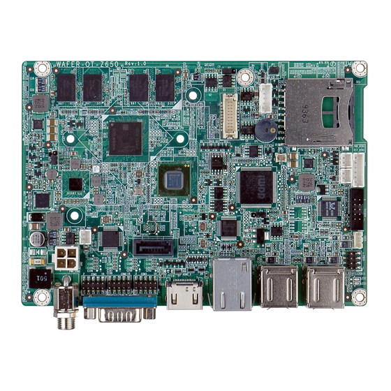
WAFER-OT-Z650/Z670 3.5" Motherboard 1.1 Introduction Figure 1-1: WAFER-OT-Z650/Z670 The WAFER-OT-Z650/Z670 3.5” motherboard is an Intel® Atom™ Z650/Z670 processor platform with on-board 1.0 GB DDR2 memory. The WAFER-OT-Z650/Z670 supports HDMI display output and comes with an LVDS connector supported 18-bit single-channel LVDS screens. -
Page 16: Connectors
WAFER-OT-Z650/Z670 3.5" Motherboard 1.3 Connectors The connectors on the WAFER-OT-Z650/Z670 are shown in the figure below. Figure 1-2: Connectors Page 3... -
Page 17: Dimensions
WAFER-OT-Z650/Z670 3.5" Motherboard 1.4 Dimensions The main dimensions of the WAFER-OT-Z650/Z670 are shown in the diagram below. Figure 1-3: WAFER-OT-Z650/Z670 Dimensions (mm) Figure 1-4: External Interface Panel Dimensions (mm) Page 4... -
Page 18: Data Flow
WAFER-OT-Z650/Z670 3.5" Motherboard 1.5 Data Flow F igure 1-5 shows the data flow between the system chipset, the CPU and other components installed on the motherboard. Figure 1-5: Data Flow Diagram Page 5... -
Page 19: Technical Specifications
WAFER-OT-Z650/Z670 3.5" Motherboard 1.6 Technical Specifications The WAFER-OT-Z650/Z670 technical specifications are listed below. Specification/Model WAFER-OT-Z650/Z670 3.5” Form Factor 1.2 GHz Intel® Atom™ Z650 processor or System CPU 1.5 GHz Intel® Atom™ Z670 processor System Chipset Intel® SM35 Memory On-board 800 MHz 1.0 GB DDR2 SDRAM Graphics Intel®... -
Page 20: Table 1-2: Wafer-Ot-Z650/Z670 Specifications
WAFER-OT-Z650/Z670 3.5" Motherboard Specification/Model WAFER-OT-Z650/Z670 -10ºC ~ 60ºC Operating Temperature Storage Temperature -20ºC ~ 70ºC Humidity (Operating) 5% ~ 95% (non-condensing) Dimensions (LxW) 146 mm x 102 mm Weight (GW/NW) 450 g / 130 g Table 1-2: WAFER-OT-Z650/Z670 Specifications Page 7... -
Page 21: Packing List
WAFER-OT-Z650/Z670 3.5" Motherboard Chapter Packing List Page 8... -
Page 22: Anti-Static Precautions
Only handle the edges of the PCB: Don't touch the surface of the motherboard. Hold the motherboard by the edges when handling. 2.2 Unpacking Precautions When the WAFER-OT-Z650/Z670 is unpacked, please do the following: Follow the antistatic guidelines above. Make sure the packing box is facing upwards when opening. -
Page 23: Packing List
If any of the components listed in the checklist below are missing, do not proceed with the installation. Contact the IEI reseller or vendor the WAFER-OT-Z650/Z670 was purchased from or contact an IEI sales representative directly by sending an email to ales@iei.com.tw. -
Page 24: Table 2-1: Packing List
WAFER-OT-Z650/Z670 3.5" Motherboard Quantity Item and Part Number Image One Key Recovery CD Utility CD Quick Installation Guide Table 2-1: Packing List Page 11... -
Page 25: Connectors
WAFER-OT-Z650/Z670 3.5" Motherboard Chapter Connectors Page 12... -
Page 26: Peripheral Interface Connectors
WAFER-OT-Z650/Z670 3.5" Motherboard 3.1 Peripheral Interface Connectors This chapter details all the jumpers and connectors. 3.1.1 WAFER-OT-Z650/Z670 Layout The figure below shows all the connectors and jumpers. Figure 3-1: Connectors and Jumpers 3.1.2 Peripheral Interface Connectors The table below lists all the connectors on the board. -
Page 27: External Interface Panel Connectors
WAFER-OT-Z650/Z670 3.5" Motherboard Connector Type Label Audio connector 10-pin box header AUDIO1 Backlight inverter connector 5-pin wafer INV1 Battery connector 2-pin wafer LVDS connector 20-pin crimp LVDS1 Power & HDD LED connector 6-pin header Power button connector 2-pin wafer PWR_BTN1... -
Page 28: Internal Peripheral Connectors
WAFER-OT-Z650/Z670 3.5" Motherboard 3.2 Internal Peripheral Connectors The section describes all of the connectors on the WAFER-OT-Z650/Z670. 3.2.1 5 V SATA Power Connector CN Label: SATA_PWR1 2-pin wafer CN Type: CN Location: See Figure 3-2 CN Pinouts: See Table 3-3 Use the 5 V SATA power connector to connect to SATA device power connection. -
Page 29: Audio Connector
WAFER-OT-Z650/Z670 3.5" Motherboard CN Location: See Figure 3-3 CN Pinouts: See Table 3-4 The ATX power connector connects to an ATX power supply. Figure 3-3: 12 V Power Connector Location Description +12V +12V Table 3-4: 12 V Power Connector Pinouts 3.2.3 Audio Connector... -
Page 30: Backlight Inverter Connector
3.2.4 Backlight Inverter Connector CN Label: INV1 5-pin wafer CN Type: CN Location: See Figure 3-5 CN Pinouts: See Table 3-6 The backlight inverter connector provides the backlights on the LCD display connected to the WAFER-OT-Z650/Z670 with +12V of power. Page 17... -
Page 31: Battery Connector
WAFER-OT-Z650/Z670 3.5" Motherboard Figure 3-5: Panel Backlight Connector Location Description LCD_BKLTCTL GROUND VCC12 GROUND LCD_BKLEN Table 3-6: Panel Backlight Connector Pinouts 3.2.5 Battery Connector CAUTION: Risk of explosion if battery is replaced by an incorrect type. Only certified engineers should replace the on-board battery. -
Page 32: Lvds Connector
WAFER-OT-Z650/Z670 3.5" Motherboard This is connected to the system battery. The battery provides power to the system clock to retain the time when power is turned off. Figure 3-6: Battery Connector Location Description Battery+ Table 3-7: Battery Connector Pinouts 3.2.6 LVDS Connector... -
Page 33: Power & Hdd Led Connector
WAFER-OT-Z650/Z670 3.5" Motherboard Figure 3-7: LVDS Connector Location Description Description AY0+ AY0- AY1+ AY1- AY2+ AY2- AYCLK+ AYCLK- AY3+ AY3- LCDVCC LCDVCC LCDVCC LCDVCC Table 3-8: LVDS Connector Pinouts 3.2.7 Power & HDD LED Connector CN Label: 6-pin wafer CN Type:... -
Page 34: Power Button Connector
WAFER-OT-Z650/Z670 3.5" Motherboard Figure 3-8: Power & HDD LED Connector Location Description Power LED+ Power LED- HDD LED+ HDD LED- Table 3-9: Power & HDD LED Connector Pinouts 3.2.8 Power Button Connector CN Label: PWR_BTN1 2-pin wafer CN Type: CN Location:... -
Page 35: Reset Button Connector
WAFER-OT-Z650/Z670 3.5" Motherboard Figure 3-9: Power Button Connector Location Description PWR_BTN+ PWR_BTN- Table 3-10: Power Button Connector Pinouts 3.2.9 Reset Button Connector CN Label: RST_BTN1 CN Type: 2-pin wafer CN Location: See Figure 3-10 CN Pinouts: See Table 3-11 The reset button connector is connected to a reset switch on the system chassis to enable users to reboot the system when the system is turned on. -
Page 36: Serial Port Connectors
WAFER-OT-Z650/Z670 3.5" Motherboard Description RESET+ RESET- Table 3-11: Reset Button Connector Pinouts 3.2.10 RS-232 Serial Port Connectors CN Label: COM2, COM3, COM4 CN Type: 10-pin header CN Location: See Figure 3-11 CN Pinouts: See Table 3-12 Each of these connectors provides RS-232 connections. -
Page 37: Sata Drive Connector
WAFER-OT-Z650/Z670 3.5" Motherboard 3.2.11 SATA Drive Connector CN Label: SATA1 7-pin SATA drive connector CN Type: CN Location: See Figure 3-12 CN Pinouts: See Table 3-13 The SATA drive connector can be connected to SATA drive and supports up to 3Gb/s data transfer rate. -
Page 38: Sd Card Slot
WAFER-OT-Z650/Z670 3.5" Motherboard 3.2.12 SD Card Slot CN Label: SD card slot CN Type: CN Location: See Figure 3-13 An SD memory card can be installed to the SD card slot for storage purpose. Figure 3-13: SD Card Slot Location 3.2.13 USB Connector (4-Pin) -
Page 39: Usb Connector (8-Pin)
WAFER-OT-Z650/Z670 3.5" Motherboard Figure 3-14: 4-pin USB Connector Location Description Description -USB +USB Table 3-14: 4-pin USB Connector Pinouts 3.2.14 USB Connector (8-Pin) CN Label: USB2 8-pin header CN Type: CN Location: See Figure 3-15 CN Pinouts: See Table 3-15 The 8-pin USB connector provides connectivity to two USB 1.1/2.0 ports. -
Page 40: External Peripheral Interface Connector Panel
WAFER-OT-Z650/Z670 3.5" Motherboard Description Description DATA+ DATA- USB_VCC Table 3-15: 8-pin USB Connector Pinouts 3.3 External Peripheral Interface Connector Panel The figure below shows the external peripheral interface connector (EPIC) panel. The EPIC panel consists of the following: Figure 3-16: External Peripheral Interface Connector 3.3.1 12 V Power Jack... -
Page 41: Ethernet Connector
CN Pinouts: See Table 3-17 The WAFER-OT-Z650/Z670 is equipped with a built-in RJ-45 Ethernet controller. The controller can connect to the LAN through a RJ-45 LAN connector. There are two LEDs on the connector indicating the status of LAN. The pin assignments are listed in the following... -
Page 42: Hdmi Connector
WAFER-OT-Z650/Z670 3.5" Motherboard 3.3.3 HDMI Connector CN Label: HDMI1 HDMI connector CN Type: CN Location: See Figure 3-16 CN Pinouts: See Table 3-19 Connects to a screen or device that accepts HDMI video input. Description Description HDMI_DATA2 HDMI_DATA2# HDMI_SCL HDMI_DATA1... -
Page 43: Usb Connectors
WAFER-OT-Z650/Z670 3.5" Motherboard Description Description DATA CARRIER DETECT (DCD) DATA SET READY (DSR) REQUEST TO SEND (RTS) RECEIVE DATA (RXD) TRANSMIT DATA (TXD) CLEAR TO SEND (CTS) DATA TERMINAL READY (DTR) RING INDICATOR (RI) Table 3-20: RS-232 Serial Port (COM 1) Pinouts Figure 3-18: COM1 Pinout Locations 3.3.5 USB Connectors... -
Page 44: Installation
WAFER-OT-Z650/Z670 3.5" Motherboard Chapter Installation Page 31... -
Page 45: Anti-Static Precautions
WAFER-OT-Z650/Z670 and severe injury to the user. Electrostatic discharge (ESD) can cause serious damage to electronic components, including the WAFER-OT-Z650/Z670. Dry climates are especially susceptible to ESD. It is therefore critical that whenever the WAFER-OT-Z650/Z670 or any other electrical component is handled, the following anti-static precautions are strictly adhered to. -
Page 46: Sd Card Installation
Allow screws to come in contact with the PCB circuit, connector pins, or its components. 4.3 SD Card Installation The WAFER-OT-Z650/Z670 provides an SD card slot for storage purpose. To install an SD card onto the WAFER-OT-Z650/Z670, please follow the steps below: Page 33... -
Page 47: Jumper Settings
WAFER-OT-Z650/Z670 3.5" Motherboard Step 1: Locate the SD card slot. Place the WAFER-OT-Z650/Z670 on an anti-static pad. Locate the SD card slot. Step 2: Align the SD card. Make sure the SD card is properly aligned with the SD card slot. -
Page 48: At/Atx Power Select Jumper
WAFER-OT-Z650/Z670 3.5" Motherboard Description Label Type AT/ATX power mode setting 3-pin switch LVDS1 voltage select J_VLVDS1 3-pin header Table 4-1: Jumpers 4.4.1 AT/ATX Power Select Jumper Jumper Label: Jumper Type: 3-pin switch Jumper Settings: See Table 4-2 See Figure 4-2 Jumper Location: The AT/ATX power select jumper specifies the system power mode as AT or ATX. -
Page 49: Lvds Voltage Selection
WAFER-OT-Z650/Z670 3.5" Motherboard 4.4.2 LVDS Voltage Selection WARNING: Permanent damage to the screen and WAFER-OT-Z650/Z670 may occur if the wrong voltage is selected with this jumper. Please refer to the user guide that came with the monitor to select the correct voltage. -
Page 50: Chassis Installation
The WAFER-OT-Z650/Z670 must be installed in a chassis with ventilation holes on the sides allowing airflow to travel through the heat sink surface. In a system with an individual power supply unit, the cooling fan of a power supply can also help generate airflow through the board surface. -
Page 51: Audio Kit Installation
WAFER-OT-Z650/Z670 3.5" Motherboard 4.6.1 Audio Kit Installation The Audio Kit that came with the WAFER-OT-Z650/Z670 connects to the 10-pin audio connector on the WAFER-OT-Z650/Z670. The audio kit consists of three audio jacks. One audio jack, Mic In, connects to a microphone. The remaining two audio jacks, Line-In and Line-Out, connect to two speakers. -
Page 52: Lvds Lcd Installation
WAFER-OT-Z650/Z670 3.5" Motherboard 4.6.2 LVDS LCD Installation The WAFER-OT-Z650/Z670 can be connected to a TFT LCD screen through the 20-pin LVDS crimp connector board. connect WAFER-OT-Z650/Z670, please follow the steps below. Step 1: Locate the connector. The location of the LVDS connector is shown in Chapter 3. -
Page 53: Figure 4-5: Lvds Connector
WAFER-OT-Z650/Z670 3.5" Motherboard Figure 4-5: LVDS Connector Step 3: Locate the backlight inverter connector. The location of the backlight inverter connector is shown in Chapter 3. Step 4: Connect backlight connector. Connect the backlight connector to the driver TFT LCD PCB as shown in Figure 4-6. When inserting the cable connector, make sure the pins are properly aligned. -
Page 54: Sata Drive Connection
WAFER-OT-Z650/Z670 3.5" Motherboard Figure 4-6: Backlight Inverter Connection 4.6.3 SATA Drive Connection The WAFER-OT-Z650/Z670 is shipped with a SATA drive cable. To connect the SATA drive to the connector, please follow the steps below. Step 1: Locate the SATA connector and the SATA power connector. The locations of the connectors are shown in Chapter 3. -
Page 55: Single Rs-232 Cable
WAFER-OT-Z650/Z670 3.5" Motherboard Figure 4-7: SATA Drive Cable Connection Step 3: Connect the cable to the SATA disk. Connect the connector on the other end of the cable to the connector at the back of the SATA drive. See Figure 4-7. -
Page 56: Usb Cable
4.6.5 USB Cable The WAFER-OT-Z650/Z670 is shipped with a dual port USB 2.0 cable. To connect the USB cable connector, please follow the steps below. Step 1: Locate the connectors. -
Page 57: External Peripheral Interface Connection
WAFER-OT-Z650/Z670 3.5" Motherboard Step 3: Insert the cable connectors. Once the cable connectors are properly aligned with the USB connectors on the WAFER-OT-Z650/Z670, connect the cable connectors to the on-board connectors. See Figure 4-9. Figure 4-9: Dual USB Cable Connection Step 4: Attach the USB connectors to the chassis. -
Page 58: Serial Device Connection
RJ-45 connector into the on-board RJ-45 connector. 4.7.2 Serial Device Connection The WAFER-OT-Z650/Z670 has a single male DB-9 connector on the external peripheral interface panel for a serial device. Follow the steps below to connect a serial device to the WAFER-OT-Z650/Z670. -
Page 59: Usb Connection (Dual Connector)
WAFER-OT-Z650/Z670 3.5" Motherboard Figure 4-11: Serial Device Connector Step 3: Secure the connector. Secure the serial device connector to the external interface by tightening the two retention screws on either side of the connector. 4.7.3 USB Connection (Dual Connector) The external USB Series "A" receptacle connectors provide easier and quicker access to external USB devices. -
Page 60: Hdmi Display Device Connection
Figure 4-12: USB Connector 4.7.4 HDMI Display Device Connection The HDMI connector transmits a digital signal to compatible HDMI display devices such as a TV or computer screen. To connect the HDMI cable to the WAFER-OT-Z650/Z670, follow the steps below. Step 1: Locate the HDMI connector. -
Page 61: Figure 4-13: Hdmi Connection
WAFER-OT-Z650/Z670 3.5" Motherboard Figure 4-13: HDMI Connection Step 3: Insert the HDMI connector. Gently insert the HDMI connector. The connector should engage with a gentle push. If the connector does not insert easily, check again that the connector is aligned correctly, and that the connector is being inserted with the right way up. -
Page 62: Bios
WAFER-OT-Z650/Z670 3.5" Motherboard Chapter BIOS Page 49... -
Page 63: Introduction
WAFER-OT-Z650/Z670 3.5" Motherboard 5.1 Introduction The BIOS is programmed onto the BIOS chip. The BIOS setup program allows changes to certain system settings. This chapter outlines the options that can be changed. 5.1.1 Starting Setup The UEFI BIOS is activated when the computer is turned on. The setup program can be activated in one of two ways. -
Page 64: Getting Help
WAFER-OT-Z650/Z670 3.5" Motherboard Function Esc key Main Menu – Quit and not save changes into CMOS Status Page Setup Menu and Option Page Setup Menu -- Exit current page and return to Main Menu General help, only for Status Page Setup Menu and Option... -
Page 65: Main
WAFER-OT-Z650/Z670 3.5" Motherboard 5.2 Main The Main BIOS menu (BIOS Menu 1) appears when the BIOS Setup program is entered. The Main menu gives an overview of the basic system information. Aptio Setup Utility – Copyright (C) 2011 American Megatrends, Inc. -
Page 66: Advanced
WAFER-OT-Z650/Z670 3.5" Motherboard The System Overview field also has two user configurable fields: System Date [xx/xx/xx] Use the System Date option to set the system date. Manually enter the day, month and year. System Time [xx:xx:xx] Use the System Time option to set the system time. Manually enter the hours, minutes and seconds. -
Page 67: Acpi Settings
WAFER-OT-Z650/Z670 3.5" Motherboard 5.3.1 ACPI Settings The ACPI Settings menu (BIOS Menu 3) configures the Advanced Configuration and Power Interface (ACPI) options. Aptio Setup Utility – Copyright (C) 2011 American Megatrends, Inc. Advanced ACPI Sleep State [S3 (Suspend to RAM)]... -
Page 68: Cpu Configuration
WAFER-OT-Z650/Z670 3.5" Motherboard 5.3.2 CPU Configuration Use the CPU Configuration menu (BIOS Menu 4) to view detailed CPU specifications and configure the CPU. Aptio Setup Utility – Copyright (C) 2011 American Megatrends, Inc. Advanced CPU Configuration Type Intel(R) Atom(TM) CPU... -
Page 69: Ide Configuration
WAFER-OT-Z650/Z670 3.5" Motherboard 5.3.3 IDE Configuration Use the IDE Configuration menu (BIOS Menu 5) to change and/or set the configuration of the SATA devices installed in the system. Aptio Setup Utility – Copyright (C) 2011 American Megatrends, Inc. Advanced IDE Configuration... -
Page 70: Usb Configuration
WAFER-OT-Z650/Z670 3.5" Motherboard 5.3.4 USB Configuration Use the USB Configuration menu (BIOS Menu 6) to read USB configuration information and configure the USB settings. Aptio Setup Utility – Copyright (C) 2011 American Megatrends, Inc. Advanced USB Configuration Enables Legacy USB support. -
Page 71: F81216 Super Io Configuration
WAFER-OT-Z650/Z670 3.5" Motherboard 5.3.5 F81216 Super IO Configuration Use the F81216 Super IO Configuration menu (BIOS Menu 7) to set or change the configurations for the serial ports. Aptio Setup Utility – Copyright (C) 2011 American Megatrends, Inc. Advanced F81216 Super IO Configuration... - Page 72 WAFER-OT-Z650/Z670 3.5" Motherboard 5.3.5.1.1 Serial Port 1 Configuration Serial Port [Enabled] Use the Serial Port option to enable or disable the serial port. Disabled Disable the serial port Enable the serial port Enabled EFAULT Change Settings [Auto] Use the Change Settings option to change the serial port IO port address and interrupt address.
- Page 73 WAFER-OT-Z650/Z670 3.5" Motherboard 5.3.5.1.2 F81216 Serial Port 2 Configuration Serial Port [Enabled] Use the Serial Port option to enable or disable the serial port. Disabled Disable the serial port Enable the serial port Enabled EFAULT Change Settings [Auto] Use the Change Settings option to change the serial port IO port address and interrupt address.
- Page 74 WAFER-OT-Z650/Z670 3.5" Motherboard Change Settings [Auto] Use the Change Settings option to change the serial port IO port address and interrupt address. Auto The serial port IO port address and interrupt address EFAULT are automatically detected. Serial Port I/O port address is 3E8h and the interrupt IO=3E8h;...
-
Page 75: Iwdd Hardware Monitor
WAFER-OT-Z650/Z670 3.5" Motherboard Auto The serial port IO port address and interrupt address EFAULT are automatically detected. Serial Port I/O port address is 2E8h and the interrupt IO=2E8h; address is IRQ10 IRQ=10 IO=3E8h; Serial Port I/O port address is 3E8h and the interrupt... -
Page 76: Chipset
WAFER-OT-Z650/Z670 3.5" Motherboard The following system voltages are monitored VCC_Core VNN_Core V1.05 V1.8_DDR V1.22 VCC_5S VCC_5A VCC_12V 5.4 Chipset Use the Chipset menu (BIOS Menu 10) to access the Northbridge and Southbridge configuration menus. WARNING! Setting the wrong values for the Chipset BIOS selections in the Chipset BIOS menu may cause the system to malfunction. -
Page 77: North Bridge Configuration
WAFER-OT-Z650/Z670 3.5" Motherboard 5.4.1 North Bridge Configuration Use the North Bridge Configuration menu (BIOS Menu 11) to configure the Northbridge chipset. Aptio Setup Utility – Copyright (C) 2011 American Megatrends, Inc. Chipset Memory Information Configure Fixed Graphics Memory Size Total Memory... -
Page 78: South Bridge Configuration
WAFER-OT-Z650/Z670 3.5" Motherboard 5.4.2 South Bridge Configuration Use the South Bridge Configuration menu (BIOS Menu 12) to configure the Southbridge chipset. Aptio Setup Utility – Copyright (C) 2011 American Megatrends, Inc. Chipset Audio Configuration Audio Controller options Audio Controller [Azalia]... -
Page 79: Boot
WAFER-OT-Z650/Z670 3.5" Motherboard All USB Ports [Enabled] Use the All USB Ports option to enable or disable all the USB ports on the system. USB ports disabled Disabled Enabled USB ports enabled EFAULT 5.5 Boot Use the Boot menu (BIOS Menu 13) to configure system boot options. -
Page 80: Security
WAFER-OT-Z650/Z670 3.5" Motherboard 5.6 Security Use the Security menu (BIOS Menu 14) to set system and user passwords. Aptio Setup Utility – Copyright (C) 2011 American Megatrends, Inc. Main Advanced Chipset Boot Security Save & Exit Password Description Set Setup Administrator Password If ONLY the Administrator’s password is set,... -
Page 81: Bios Menu 15:Exit
WAFER-OT-Z650/Z670 3.5" Motherboard Aptio Setup Utility – Copyright (C) 2011 American Megatrends, Inc. Main Advanced Chipset Boot Security Save & Exit Save Changes and Reset Reset the system after Discard Changes and Reset saving the changes. Restore Defaults Save as User Defaults... -
Page 82: Software Drivers
WAFER-OT-Z650/Z670 3.5" Motherboard Chapter Software Drivers Page 69... -
Page 83: Available Software Drivers
Insert the CD that came with the system into a CD drive connected to the system. NOTE: If the installation program doesn't start automatically: Click "Start->Computer->CD Drive->autorun.exe" Step 2: The driver main menu appears. Click WAFER-OT-Z650/Z670. Step 3: The list of drivers appears. Page 70... -
Page 84: Chipset Driver Installation
WAFER-OT-Z650/Z670 3.5" Motherboard 6.3 Chipset Driver Installation To install the chipset driver, please do the following. Step 1: Access the driver list. (See Section 6.2) Step 2: Click “1-Chipset” Step 3: The setup files are extracted as shown in Figure 6-1. -
Page 85: Figure 6-2: Chipset Driver Welcome Screen
WAFER-OT-Z650/Z670 3.5" Motherboard Figure 6-2: Chipset Driver Welcome Screen Step 5: Click Next to continue. Step 6: The license agreement in Figure 6-3 appears. Step 7: Read the License Agreement. Step 8: Click Yes to continue. Page 72... -
Page 86: Figure 6-3: Chipset Driver License Agreement
WAFER-OT-Z650/Z670 3.5" Motherboard Figure 6-3: Chipset Driver License Agreement Step 9: The Read Me file in Figure 6-4 appears. Step 10: Click Next to continue. Figure 6-4: Chipset Driver Read Me File Page 73... -
Page 87: Figure 6-5: Chipset Driver Setup Operations
WAFER-OT-Z650/Z670 3.5" Motherboard Step 11: Setup Operations are performed as shown in Figure 6-5. Figure 6-5: Chipset Driver Setup Operations Step 12: Once the Setup Operations are complete, click Next to continue. Step 13: The Finish screen appears. Step 14: Select “Yes, I want to restart the computer now”... -
Page 88: Vga Driver Installation
WAFER-OT-Z650/Z670 3.5" Motherboard Figure 6-6: Chipset Driver Installation Finish Screen 6.4 VGA Driver Installation To install the VGA driver, please do the following. Step 1: Access the driver list. (See Section 6.2) Step 2: Click “2-VGA” Step 3: The Welcome Screen in Figure 6-7 appears. -
Page 89: Figure 6-7: Vga Driver Welcome Screen
WAFER-OT-Z650/Z670 3.5" Motherboard Figure 6-7: VGA Driver Welcome Screen Step 4: Click Next to continue. Step 5: The license agreement in Figure 6-8 appears. Step 6: Read the License Agreement. Step 7: Click the Yes icon to continue. Page 76... -
Page 90: Figure 6-8: Vga Driver License Agreement
WAFER-OT-Z650/Z670 3.5" Motherboard Figure 6-8: VGA Driver License Agreement Step 8: The Read Me file in Figure 6-9 appears. Step 9: Click Next to continue. Figure 6-9: VGA Driver Read Me File Page 77... -
Page 91: Figure 6-10: Vga Driver Setup Operations
WAFER-OT-Z650/Z670 3.5" Motherboard Step 10: Setup Operations are performed as shown in Figure 6-10. Figure 6-10: VGA Driver Setup Operations Step 11: Once the Setup Operations are complete, click the Next icon to continue. Step 12: The Finish screen appears. -
Page 92: Lan Driver Installation
WAFER-OT-Z650/Z670 3.5" Motherboard Figure 6-11: VGA Driver Installation Finish Screen 6.5 LAN Driver Installation To install the LAN driver, please do the following. Step 1: Open Windows Control Panel from the Start menu (Figure 6-12). Figure 6-12: Access Windows Control Panel... -
Page 93: Figure 6-13: Double Click The System Icon
WAFER-OT-Z650/Z670 3.5" Motherboard Step 2: Double-click the System icon (Figure 6-13). Figure 6-13: Double Click the System Icon Step 3: Click the Device Manager tab (Figure 6-14). Figure 6-14: Click the Device Manager Tab Page 80... -
Page 94: Figure 6-15: Device Manager List
WAFER-OT-Z650/Z670 3.5" Motherboard Step 4: A list of system hardware devices appears (Figure 6-15). Figure 6-15: Device Manager List Step 5: Double-click the AX88772 device. Step 6: The AX88772 Properties window appears (Figure 6-16). Page 81... -
Page 95: Figure 6-16: Ax88772 Properties Window
WAFER-OT-Z650/Z670 3.5" Motherboard Figure 6-16: AX88772 Properties Window Step 7: Click the Update Driver button in the Driver tab. Step 8: The following window (Figure 6-17) appears. Figure 6-17: Search Options Window Page 82... -
Page 96: Figure 6-18: Driver Selection Window
WAFER-OT-Z650/Z670 3.5" Motherboard Step 9: Click “Browse my computer for driver software”. Step 10: The following window (Figure 6-18) appears. Figure 6-18: Driver Selection Window Step 11: Select “Include subfolders,” and click Browse to continue. Step 12: The following window (Figure 6-19) appears. -
Page 97: Figure 6-20: Driver Location Window
WAFER-OT-Z650/Z670 3.5" Motherboard Step 14: The following window (Figure 6-20) appears. Figure 6-20: Driver Location Window Step 15: Click Next to continue. Step 16: The following window (Figure 6-21) appears as the driver is installed. Figure 6-21: Driver Installation Window... -
Page 98: Figure 6-22: Driver Installation Complete Window
WAFER-OT-Z650/Z670 3.5" Motherboard Step 17: After the driver installation process is complete, a confirmation screen appears (Figure 6-22). Figure 6-22: Driver Installation Complete Window Step 18: Click Close to exit the program. Step 19: The Device Manager Window now shows the installed LAN driver (Figure 6-23). -
Page 99: Audio Driver Installation
WAFER-OT-Z650/Z670 3.5" Motherboard 6.6 Audio Driver Installation To install the Audio driver, please do the following. Step 1: Access the driver list. (See Section 6.2) Step 2: Click “4-Audio”. Step 3: The installation files are extracted as shown in Figure 6-24. -
Page 100: Figure 6-25: Audio Driver Welcome Screen
WAFER-OT-Z650/Z670 3.5" Motherboard Figure 6-25: Audio Driver Welcome Screen Step 5: Click Next to continue. Step 6: The program begins to install. Step 7: The installation progress can be monitored in the progress bar shown in Figure 6-26. Figure 6-26: Audio Driver Installation... -
Page 101: Figure 6-27: Audio Driver Installation Complete
WAFER-OT-Z650/Z670 3.5" Motherboard Step 8: When the driver installation is complete, the screen in Figure 6-27 appears. Figure 6-27: Audio Driver Installation Complete Step 9: Select “Yes, I want to restart my computer now” and click Finish. Step 10: The system reboots. -
Page 102: Abios Options
WAFER-OT-Z650/Z670 3.5" Motherboard Appendix BIOS Options Page 89... - Page 103 WAFER-OT-Z650/Z670 3.5" Motherboard Below is a list of BIOS configuration options in the BIOS chapter. System Overview .........................52 Memory Information ......................52 System Date [xx/xx/xx] ......................53 System Time [xx:xx:xx] .......................53 ACPI Sleep State [S3 (Suspend to RAM)]................54 ...
-
Page 104: B One Key Recovery
WAFER-OT-Z650/Z670 3.5" Motherboard Appendix One Key Recovery Page 91... -
Page 105: One Key Recovery Introduction
WAFER-OT-Z650/Z670 3.5" Motherboard B.1 One Key Recovery Introduction The IEI one key recovery is an easy-to-use front end for the Norton Ghost system backup and recovery tool. This tool provides quick and easy shortcuts for creating a backup and reverting to that backup or reverting to the factory default settings. -
Page 106: System Requirement
WAFER-OT-Z650/Z670 3.5" Motherboard After completing the five initial setup procedures as described above, users can access the recovery tool by pressing <F3> while booting up the system. The detailed information of each function is described in Section B.5. NOTE: The initial setup procedures for Linux system are described in Section B .3. -
Page 107: Supported Operating System
WAFER-OT-Z650/Z670 3.5" Motherboard partitions. Please take the following table as a reference when calculating the size of the partition. OS Image after Ghost Compression Ratio Windows® 7 7 GB 5 GB Windows® XPE 776 MB 560 MB Windows® CE 6.0... -
Page 108: Setup Procedure For Windows
WAFER-OT-Z650/Z670 3.5" Motherboard Linux Fedora Core 12 (Constantine) Fedora Core 11 (Leonidas) Fedora Core 10 (Cambridge) Fedora Core 8 (Werewolf) Fedora Core 7 (Moonshine) RedHat RHEL-5.4 RedHat 9 (Ghirke) Ubuntu 8.10 (Intrepid) Ubuntu 7.10 (Gutsy) Ubuntu 6.10 (Edgy) Debian 5.0 (Lenny) Debian 4.0 (Etch) -
Page 109: Hardware And Bios Setup
WAFER-OT-Z650/Z670 3.5" Motherboard The detailed descriptions are described in the following sections. NOTE: The setup procedures described below are for Microsoft Windows operating system users. For Linux, most of the setup procedures are the same except for several steps described in Section B .3. -
Page 110: Figure B-2: Launching The Recovery Tool
WAFER-OT-Z650/Z670 3.5" Motherboard Step 2: Boot the system from recovery CD. When prompted, press any key to boot from the recovery CD. It will take a while to launch the recovery tool. Please be patient! Figure B-2: Launching the Recovery Tool Step 3: The recovery tool setup menu is shown as below. -
Page 111: Figure B-4: Command Mode
WAFER-OT-Z650/Z670 3.5" Motherboard Figure B-4: Command Mode Step 5: The command prompt window appears. Type the following commands (marked in red) to create two partitions. One is for the OS installation; the other is for saving recovery files and images which will be an invisible partition. -
Page 112: Figure B-5: Partition Creation Commands
WAFER-OT-Z650/Z670 3.5" Motherboard Figure B-5: Partition Creation Commands Page 99... -
Page 113: Install Operating System, Drivers And Applications
WAFER-OT-Z650/Z670 3.5" Motherboard NOTE: Use the following commands to check if the partitions were created successfully. Step 6: Press any key to exit the recovery tool and automatically reboot the system. Please continue to the following procedure: Build the Recovery Partition.S t e p 0 :... -
Page 114: Build-Up Recovery Partition
WAFER-OT-Z650/Z670 3.5" Motherboard B.2.4 Build-up Recovery Partition Step 1: Put the recover CD in the optical drive. Step 2: Start the system. Step 3: Boot the system from the recovery CD. When prompted, press any key to boot from the recovery CD. It will take a while to launch the recovery tool. Please... -
Page 115: Figure B-8: Building The Recovery Partition
WAFER-OT-Z650/Z670 3.5" Motherboard Step 5: The Symantec Ghost window appears and starts configuring the system to build a recovery partition. In this process the partition created for recovery files in Section B .2.2 is hidden and the recovery tool is saved in this partition. -
Page 116: Create Factory Default Image
WAFER-OT-Z650/Z670 3.5" Motherboard B.2.5 Create Factory Default Image NOTE: Before creating the factory default image, please configure the system to a factory default environment, including driver and application installations. To create a factory default image, please follow the steps below. -
Page 117: Figure B-12: About Symantec Ghost Window
WAFER-OT-Z650/Z670 3.5" Motherboard Figure B-12: About Symantec Ghost Window Step 4: Use mouse to navigate to the option shown below ( F igure B-13). Figure B-13: Symantec Ghost Path Step 5: Select the local source drive (Drive 1) as shown in F igure B-14. -
Page 118: Figure B-14: Select A Local Source Drive
WAFER-OT-Z650/Z670 3.5" Motherboard Figure B-14: Select a Local Source Drive Step 6: Select a source partition (Part 1) from basic drive as shown in F igure B-15. Then click OK. Figure B-15: Select a Source Partition from Basic Drive Step 7: Select 1.2: [Recovery] NTFS drive and enter a file name called... -
Page 119: Figure B-16: File Name To Copy Image To
WAFER-OT-Z650/Z670 3.5" Motherboard Figure B-16: File Name to Copy Image to Step 8: When the Compress Image screen in F igure B-17 prompts, click High to make the image file smaller. Figure B-17: Compress Image Page 106... -
Page 120: Figure B-18: Image Creation Confirmation
WAFER-OT-Z650/Z670 3.5" Motherboard Step 9: The Proceed with partition image creation window appears, click Yes to continue. Figure B-18: Image Creation Confirmation Step 10: The Symantec Ghost starts to create the factory default image ( F igure B-19). Figure B-19: Image Creation Complete... -
Page 121: Auto Recovery Setup Procedure
WAFER-OT-Z650/Z670 3.5" Motherboard Step 12: The recovery tool main menu window is shown as below. Press any key to reboot the system. S t e p 0 : Figure B-21: Press Any Key to Continue B.3 Auto Recovery Setup Procedure... -
Page 122: Figure B-22: Auto Recovery Utility
WAFER-OT-Z650/Z670 3.5" Motherboard Step 1: Follow the steps described in Section B.2.1 ~ Section B.2.3 to setup BIOS, create partitions and install operating system. Step 2: Install the auto recovery utility into the system by double clicking the Utility/AUTORECOVERY-SETUP.exe in the One Key Recovery CD. This utility MUST be installed in the system, otherwise, the system will automatically restore from the factory default image every ten (10) minutes. -
Page 123: Figure B-24: Launching The Recovery Tool
WAFER-OT-Z650/Z670 3.5" Motherboard Step 4: Reboot the system from the recovery CD. When prompted, press any key to boot from the recovery CD. It will take a while to launch the recovery tool. Please be patient! Figure B-24: Launching the Recovery Tool Step 5: When the recovery tool setup menu appears, press <4>... -
Page 124: Figure B-26: Building The Auto Recovery Partition
WAFER-OT-Z650/Z670 3.5" Motherboard Figure B-26: Building the Auto Recovery Partition Step 7: After completing the system configuration, the following message prompts to confirm whether to create a factory default image. Type Y to have the system create a factory default image automatically. Type N within 6 seconds to skip this process (The default option is YES). -
Page 125: Figure B-28: Image Creation Complete
WAFER-OT-Z650/Z670 3.5" Motherboard Step 8: The Symantec Ghost starts to create the factory default image (Figure B-28). Figure B-28: Image Creation Complete Step 9: After completing the system configuration, press any key in the following window to restart the system. -
Page 126: Setup Procedure For Linux
WAFER-OT-Z650/Z670 3.5" Motherboard BIOS SETUP UTILITY Main Advanced PCIPNP Boot Security Chipset Exit iEi Feature ⎯⎯⎯⎯⎯⎯⎯⎯⎯⎯⎯⎯⎯⎯⎯⎯⎯⎯⎯⎯⎯⎯⎯⎯⎯⎯⎯ Auto Recovery Function [Enabled] Recover from PXE [Disabled] Select Screen ↑ ↓ Select Item Enter Go to SubScreen General Help Save and Exit Exit v02.61 ©Copyright 1985-2006, American Megatrends, Inc. -
Page 127: Figure B-30: Partitions For Linux
WAFER-OT-Z650/Z670 3.5" Motherboard Partition 1: / Partition 2: SWAP NOTE: Please reserve enough space for partition 3 for saving recovery images. Figure B-30: Partitions for Linux Step 3: Create a recovery partition. Insert the recovery CD into the optical disk drive. -
Page 128: Figure B-31: System Configuration For Linux
WAFER-OT-Z650/Z670 3.5" Motherboard recovery partition. After completing the system configuration, press any key to reboot the system. Eject the recovery CD. Figure B-31: System Configuration for Linux Step 5: Access the recovery tool main menu by modifying the “menu.lst”. To first access the recovery tool main menu, the menu.lst must be modified. -
Page 129: Recovery Tool Functions
WAFER-OT-Z650/Z670 3.5" Motherboard Step 7: The recovery tool menu appears. ( F igure B-33) Figure B-33: Recovery Tool Menu Step 8: Create a factory default image. Follow Step 2 Step 12 described in Section B .2.5 to create a factory default image. -
Page 130: Figure B-34: Recovery Tool Main Menu
WAFER-OT-Z650/Z670 3.5" Motherboard Figure B-34: Recovery Tool Main Menu The recovery tool has several functions including: 1. Factory Restore: Restore the factory default image (iei.GHO) created in Section B .2.5. 2. Backup system: Create a system backup image (iei_user.GHO) which will be saved in the hidden partition. -
Page 131: Factory Restore
WAFER-OT-Z650/Z670 3.5" Motherboard B.5.1 Factory Restore To restore the factory default image, please follow the steps below. Step 1: Type <1> and press <Enter> in the main menu. Step 2: The Symantec Ghost window appears and starts to restore the factory default. A factory default image called iei.GHO is created in the hidden Recovery partition. -
Page 132: Backup System
WAFER-OT-Z650/Z670 3.5" Motherboard B.5.2 Backup System To backup the system, please follow the steps below. Step 1: Type <2> and press <Enter> in the main menu. Step 2: The Symantec Ghost window appears and starts to backup the system. A backup image called iei_user.GHO is created in the hidden Recovery partition. -
Page 133: Restore Your Last Backup
WAFER-OT-Z650/Z670 3.5" Motherboard B.5.3 Restore Your Last Backup To restore the last system backup, please follow the steps below. Step 1: Type <3> and press <Enter> in the main menu. Step 2: The Symantec Ghost window appears and starts to restore the last backup image (iei_user.GHO). -
Page 134: Manual
WAFER-OT-Z650/Z670 3.5" Motherboard B.5.4 Manual To restore the last system backup, please follow the steps below. Step 1: Type <4> and press <Enter> in the main menu. Step 2: The Symantec Ghost window appears. Use the Ghost program to backup or recover the system manually. -
Page 135: Restore Systems From A Linux Server Through Lan
WAFER-OT-Z650/Z670 3.5" Motherboard B.6 Restore Systems from a Linux Server through LAN The One Key Recovery allows a client system to automatically restore to a factory default image saved in a Linux system (the server) through LAN connectivity after encountering a Blue Screen of Death (BSoD) or a hang for around 10 minutes. -
Page 136: Configure Dhcp Server Settings
WAFER-OT-Z650/Z670 3.5" Motherboard B.6.1 Configure DHCP Server Settings Step 1: Install the DHCP #yum install dhcp (CentOS, commands marked in red) #apt-get install dhcp3-server (Debian, commands marked in blue) Step 2: Confirm the operating system default settings: dhcpd.conf. CentOS Use the following command to show the DHCP server sample location: #vi /etc/dhcpd.conf... -
Page 137: Configure Tftp Settings
WAFER-OT-Z650/Z670 3.5" Motherboard filename “pxelinux.0”; B.6.2 Configure TFTP Settings Step 1: Install the tftp, httpd and syslinux. #yum install tftp-server httpd syslinux (CentOS) #apt-get install tftpd-hpa xinetd syslinux (Debian) Step 2: Enable the TFTP server by editing the “/etc/xinetd.d/tftp” file and make it use the remap file. -
Page 138: Configure One Key Recovery Server Settings
WAFER-OT-Z650/Z670 3.5" Motherboard Debian Replace the TFTP settings from “inetd” to “xinetd” and annotate the “inetd” by adding “#”. #vi /etc/inetd.conf Modify: #tftp dgram udp wait root /usr/sbin..(as shown below) #vi /etc/xinetd.d/tftp B.6.3 Configure One Key Recovery Server Settings Step 1: Copy the Utility/RECOVERYR10.TAR.BZ2 package from the One Key... -
Page 139: Start The Dhcp, Tftp And Http
WAFER-OT-Z650/Z670 3.5" Motherboard B.6.4 Start the DHCP, TFTP and HTTP Start the DHCP, TFTP and HTTP. For example: CentOS #service xinetd restart #service httpd restart #service dhcpd restart Debian #/etc/init.d/xinetd reload #/etc/init.d/xinetd restart #/etc/init.d/dhcp3-server restart B.6.5 Create Shared Directory Step 1: Install the samba. -
Page 140: Setup A Client System For Auto Recovery
WAFER-OT-Z650/Z670 3.5" Motherboard Modify: [image] comment = One Key Recovery path = /share/image browseable = yes writable = yes public = yes create mask = 0644 directory mask = 0755 Step 4: Edit “/etc/samba/smb.conf” for your environment. For example: Step 5:... -
Page 141: Figure B-42: Disable Automatically Restart
WAFER-OT-Z650/Z670 3.5" Motherboard Figure B-42: Disable Automatically Restart Step 2: Configure the following BIOS options of the client system. Advanced → iEi Feature → Auto Recovery Function → Enabled Advanced → iEi Feature → Recover from PXE → Enabled Boot → Launch PXE OpROM → Enabled... - Page 142 WAFER-OT-Z650/Z670 3.5" Motherboard MUST be installed in the system, otherwise, the system will automatically restore from the factory default image every ten (10) minutes. Step 6: Restart the client system from LAN. If the system encounters a Blue Screen of Death (BSoD) or a hang for around 10 minutes, it will automatically restore from the factory default image.
-
Page 143: Other Information
WAFER-OT-Z650/Z670 3.5" Motherboard NOTE: A firewall or a SELinux is not in use in the whole setup process described above. If there is a firewall or a SELinux protecting the system, modify the configuration information to accommodate them. B.7 Other Information B.7.1 Using AHCI Mode or ALi M5283 / VIA VT6421A Controller... - Page 144 WAFER-OT-Z650/Z670 3.5" Motherboard Step 5: When the following window appears, press <S> to select “Specify Additional Device”. Page 131...
-
Page 145: System Memory Requirement
WAFER-OT-Z650/Z670 3.5" Motherboard Step 6: In the following window, select a SATA controller mode used in the system. Then press <Enter>. The user can now start using the SATA HDD. Step 7: After pressing <Enter>, the system will get into the recovery tool setup menu. -
Page 146: C Terminology
WAFER-OT-Z650/Z670 3.5" Motherboard Appendix Terminology Page 133... - Page 147 WAFER-OT-Z650/Z670 3.5" Motherboard AC ’97 Audio Codec 97 (AC’97) refers to a codec standard developed by Intel® in 1997. ACPI Advanced Configuration and Power Interface (ACPI) is an OS-directed configuration, power management, and thermal management interface. AHCI Advanced Host Controller Interface (AHCI) is a SATA Host controller register-level interface.
- Page 148 WAFER-OT-Z650/Z670 3.5" Motherboard DIMM Dual Inline Memory Modules are a type of RAM that offer a 64-bit data bus and have separate electrical contacts on each side of the module. The digital inputs and digital outputs are general control signals that control the on/off circuit of external devices or TTL devices.
- Page 149 WAFER-OT-Z650/Z670 3.5" Motherboard LVDS Low-voltage differential signaling (LVDS) is a dual-wire, high-speed differential electrical signaling system commonly used to connect LCD displays to a computer. POST The Power-on Self Test (POST) is the pre-boot actions the system performs when the system is turned-on.
-
Page 150: D Watchdog Timer
WAFER-OT-Z650/Z670 3.5" Motherboard Appendix Watchdog Timer Page 137... - Page 151 WAFER-OT-Z650/Z670 3.5" Motherboard NOTE: The following discussion applies to DOS environment. Contact IEI support or visit the IEI website for specific drivers for other operating systems. The Watchdog Timer is provided to ensure that standalone systems can always recover from catastrophic conditions that cause the CPU to crash. This condition may have occurred by external EMIs or a software bug.
- Page 152 WAFER-OT-Z650/Z670 3.5" Motherboard NOTE: When exiting a program it is necessary to disable the Watchdog Timer, otherwise the system resets. EXAMPLE PROGRAM: ; INITIAL TIMER PERIOD COUNTER W_LOOP: AX, 6F02H ;setting the time-out value BL, 30 ;time-out value is 48 seconds ;...
-
Page 153: E Hazardous Materials Disclosure
WAFER-OT-Z650/Z670 3.5" Motherboard Appendix Hazardous Materials Disclosure Page 140... -
Page 154: Hazardous Materials Disclosure Table For Ipb Products Certified As Rohs Compliant Under 2002/95/Ec Without Mercury
WAFER-OT-Z650/Z670 3.5" Motherboard E.1 Hazardous Materials Disclosure Table for IPB Products Certified as RoHS Compliant Under 2002/95/EC Without Mercury The details provided in this appendix are to ensure that the product is compliant with the Peoples Republic of China (China) RoHS standards. The table below acknowledges the presences of small quantities of certain materials in the product, and is applicable to China RoHS only. - Page 155 WAFER-OT-Z650/Z670 3.5" Motherboard Part Name Toxic or Hazardous Substances and Elements Lead Mercury Cadmium Hexavalent Polybrominated Polybrominated Biphenyls Diphenyl (Pb) (Hg) (Cd) Chromium (CR(VI)) (PBB) Ethers (PBDE) Housing Display Printed Circuit Board Metal Fasteners Cable Assembly Fan Assembly Power Supply...
- Page 156 WAFER-OT-Z650/Z670 3.5" Motherboard 此附件旨在确保本产品符合中国 RoHS 标准。以下表格标示此产品中某有毒物质的含量符 合中国 RoHS 标准规定的限量要求。 本产品上会附有”环境友好使用期限”的标签,此期限是估算这些物质”不会有泄漏或突变”的 年限。本产品可能包含有较短的环境友好使用期限的可替换元件,像是电池或灯管,这些元 件将会单独标示出来。 部件名称 有毒有害物质或元素 铅 汞 镉 六价铬 多溴联苯 多溴二苯 醚 (Pb) (Hg) (Cd) (CR(VI)) (PBB) (PBDE) 壳体 显示 印刷电路板 金属螺帽 电缆组装 风扇组装 电力供应组装 电池 O: 表示该有毒有害物质在该部件所有物质材料中的含量均在 SJ/T11363-2006 标准规定的限量要求以下。 X: 表示该有毒有害物质至少在该部件的某一均质材料中的含量超出 SJ/T11363-2006 标准规定的限量要求。...
Need help?
Do you have a question about the WAFER-OT-Z650 and is the answer not in the manual?
Questions and answers