Table of Contents
Advertisement
Quick Links
Advertisement
Table of Contents

Related Manuals for Furuno GP-280


Summary of Contents for Furuno GP-280
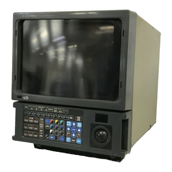
- Page 1 Back COLOR GPS PLOTTER GP-280/380/680 COLOR VIDEO PLOTTER GD-280/380/680...
- Page 2 *00080880801* *00080880801* *00080880801* *00080880801* ( ( YOSH YOSH ) ) GD/GP-280/380/680 GD/GP-280/380/680 * 0 0 0 8 0 8 8 0 8 0 1 * * 0 0 0 8 0 8 8 0 8 0 1 * *OME43890Q00* *OME43890Q00*...
- Page 3 Use of a wrong fuse can result in equipment the equipment. damage. Continued use of the equipment can cause Do not operate the equipment with wet fire or electrical shock. Contact a FURUNO hands. agent for service. Electrical shock can result. Do not disassemble or modify the equipment.
- Page 4 CAUTION A warning label is attached to the equip- ment. Do not remove the label. If the label is missing or illegible, contact a FURUNO agent or dealer. Name: Warning Label (1) WARNING Type: 86-003-1011-0 To avoid electrical shock, do not Code No.: 100-236-230...
-
Page 5: Table Of Contents
TABLE OF CONTENTS INTRODUCTION........v 5. WAYPOINTS, ROUTES 5.1 Entering Waypoints........ 5-1 SYSTEM CONFIGURATION ....vii 5.2 Editing Waypoints ........ 5-10 GP/GD-280 ...........vii 5.3 Deleting Waypoints ......5-11 GP/GD-380 ..........viii 5.4 Setting Course by Waypoints ....5-12 GP/GD-680 ........... ix 5.5 Registering, Changing, Deleting Routes........ - Page 6 11. RADAR OPERATION 13. CUSTOMIZING YOUR UNIT 11.1 Operation Panel ......... 11-1 13.1 Plotter Display Attributes.....13-1 11.2 Picture Selection ........ 11-3 13.2 Plotter Display Setup......13-17 11.3 Radar Picture Adjustment ....11-5 13.3 Graphs..........13-21 11.4 Radar Picture Functions ..... 11-8 13.4 Apportioning the Memory....13-24 11.5 Measuring Range and Bearing 13.5 Programming the Function to a Target........
-
Page 7: Introduction
Plotter GP-280/380/680, Color Video Plotter GD-280/380/680. We are confident you will discover why FURUNO has become synonymous with quality and reliability. For over 50 years FURUNO Electric Company has enjoyed an enviable reputation for efficient and dependable marine electronics equipment. This dedication to excellence is furthered by our extensive global network of agents and dealers. - Page 8 • Comprehensive navigation display of alphanumeric navigation data plus automatic track plotting. • Own ship and cursor positions may be shown in latitude and longitude, Loran A, C and Decca LOPs. • Two lines of nav data input enables display of two tracks, main and sub, simultaneously. •...
-
Page 9: System Configuration
SYSTEM CONFIGURATION GP/GD-280 GPS/DGPS Antenna Unit (GP-280 only) GPA-018S (DGPS) Whip Antenna GPA-016 (GPS) GPA-019S (DGPS) 1.2 m Display Unit GP/GD-2800 Navigation device (Required for GD-280) Radar Display Unit Ship's Mains Gyrocompass 12/24/32 VDC Speed Log Rectifier Radar Control Panel... -
Page 10: Gp/Gd-380
GP/GD-380 GPS/DGPS Antenna Unit (GP-380 only) GPA-018S (DGPS) Whip Antenna GPA-016 (GPS) GPA-019S (DGPS) 1.2 m Display Unit GP/GD-3800 Navigation device (Required for GD-380) Radar Display Ship's Mains Gyrocompass Speed Log 24/32 VDC Rectifier Radar Control Panel RU-3423 GD-2821 (Requires radar overlay kit.) 100/110/115/220/230 VAC 1φ, 50/60 Hz : Option... -
Page 11: Gp/Gd-680
GP/GD-680 GPS/DGPS Antenna Unit (GP-680 only) GPA-018S (DGPS) Whip Antenna GPA-016 (GPS) GPA-019S (DGPS) 1.2 m Display Unit GP/GD-6800 Navigation device (Required for GD-680) Radar Display Unit Gyrocompass Ship's Mains Speed Log 24/32 VDC Rectifier RU-3423 100/110/115/220/230 VAC 1φ, 50/60 Hz : Option : External Equipment... -
Page 12: Controls, Menu Operation
CONTROLS, MENU OPERATION Using the Remote Controller The remote controller provides armchair operation of the display unit from up to five meters away. It is powered by two AA batteries. Install the batteries as below. To operate the GD/GP- 280/380/680 by the remote controller, point the remote controller toward the optical sensor on the display unit and operate its keys. -
Page 13: Control Description
Control Description GP/GD-280 VIDEO PLOTTER CD-280 Display Optical sensor for POWER Switch remote controller Keyboard Trackball • Stops/resumes plotting. • Selects track color. Opens/closes waypoint entry menu. • Erases track by color. Opens/closes comment entry menu. Opens/closes main menu. Enter numerical data; select menu; select mark. Degausses screen. - Page 14 GP/GD-380 Chart Card Slot/ Memory Card Slot Floppy Disk Drive (Requires FD Kit.) GP/GD-380 Display Unit EVENT (MOB) GAUSS BRILL TRACK COLOR TRACK ON/OFF MENU ERASE LINE POWER COLOR CNTR START GOTO MARK INFO COLOR TM/RM CMNT CANCEL SHAPE ENTRY MODE DISP POWER Switch...
- Page 15 GP/GD-680 Optical Sensor Chart Card Slot/ Floppy Disk Drive Memory Card Slot (Requires FD Kit.) GP/GD-680 Display Unit : Require radar overlay kit. Inoperative otherwise; buzzer sounds when AUDIO Control operated. POWER Switch BRILL Control AUDIO BRILL A/C RAIN A/C SEA GAIN POWER EBL OFFSET(PUSH)
-
Page 16: Remote Controller
Remote Controller The remote controller provides armchair control of the display unit from a distance of up to 4 m. The remote controller keys operate exactly the same as keys on the display unit. Note 1: Power on/off, F3-F9, degauss, panel illumination and brilliance are conducted from the display unit. -
Page 17: Menu Operation
Menu Operation Most functions are carried out through the menu. This section provides information necessary for menu operation. 1. Press the [MENU] key to display the main menu. Main Menu Plotter Display Track Mark/Line Waypoint/Route Alarm File Target Point Calculate Rng/Brg System Setting Initial Setting... - Page 18 Menu conventions • Return to main menu: Press the [MENU] key several times. • Return to previous screen: Press the [MENU] key once. • Close menu: Press the [MENU] key several times. • CLR key: Clears entire line of numeric data. •...
-
Page 19: Operational Overview
1. OPERATIONAL OVERVIEW The basic function of a video plotter is to record and plot ship's track, using position data fed from a navigation device which is built in the display unit or is installed separately. Once the equipment is properly installed, you need do no more than turn on the power to plot ship's track. - Page 20 Position should be to show the confirmed against nautical plotter display. charts. FURUNO ELECTRIC CO., LTD Position in lat./long. +cursor Own ship marker (blinking) PLOTTER DISPLAY If the diagnosis finds fault, the display freezes. To restore normal operation, try to press any key.
- Page 21 1.1.3 Adjusting display brilliance, keyboard backlighting Display brilliance: For the GP/GD-280/380, press the [BRILL] key to adjust display brilliance. Eight levels of brilliance (including off) are available. For the GP/GD-680, adjust the [BRILL] control. Keyboard backlighting: Press the [DIM] key to adjust keyboard backlighting. Four levels (including off) are available.
- Page 22 1.1.7 Selecting presentation mode Three presentation modes are available: head-up, north-up, and course-up. Head-up (Radar display only): Heading is at the top of the screen. °) North-up: North (0 is at the top of the screen. This mode is useful as a general navigation monitor.
- Page 23 1.1.9 Selecting track color for main track 1. If own ship is moored at a pier or the like, turn off the cursor with , and then press enlarge the chart scale. 2. Press the [TRACK COLOR SEL] key to display the Change Track Color menu. Change Track Color ...
- Page 24 1.1.11 Erasing track by color This procedure is also effective for GPS buoy track and ARP track. 1. Press the [TRACK COLOR ERASE] key to display the Track Color Erase menu. Track Color Erase Yellow Green Cyan Purple Blue White Track Main...
- Page 25 1.1.12 Entering marks, selecting mark color and shape This section shows you how to enter a mark with the +cursor, the default mark entry method, and change mark color and shape. 1. Operate the trackball to place the +cursor on the location desired. If the +cursor is not displayed, press to display it.
- Page 26 9. Press the [MARK SHAPE] key to close the menu. 10. Place the +cursor on the location desired for a mark and press the [MARK ENT] key. The mark is inscribed in the shape and color selected here. For further details about marks, see Chapter 3. To erase individual marks, place the +cursor on the mark to erase, and press the [CLR] key.
- Page 27 Erasing lines: Place the +cursor on the line point to erase and press the [CLR] key. The line is then redrawn excluding the point erased. Connecting own ship position with a line: Turn off the +cursor with the key and follow the procedure for inscribing a line.
- Page 28 7. Operate the trackball to place the highlight on Enter. 8. Press the [ENT] key. Entered comment is placed near mark or line selected. TUNA FURUNO LINE 25 Sample comments Note 1: Comments can be turned on or off collectively from the screen by pressing [MENU], [0], [1] and setting the Comment Mark to Off or On as appropriate.
-
Page 29: Entering Waypoints
1.1.15 Entering waypoints Waypoints are mainly used to mark important positions and locations. This section shows you how to enter a waypoint by using the +cursor, the default entry method. 1. Press the [WPT ENTRY] key to display the waypoint list. Enter WPT [+Cursor] Screen 1 ↑↓: Sel CHG: Page CLR: Erase ENT: Entry Mode... - Page 30 5. Press the [ENT] key. The display should look something like the one below. 35°11.118’N 135°14.861’E Waypoint entered at this position. Number Color Y G C P B W → → → → _____________ Comment ↑↓←→: Sel ENT: Fix WPT ENTRY key : Close 6.
- Page 31 1.1.16 Setting destination Setting destination by waypoint 1. Press the [GOTO SEL] key. The following menu appears. Select WPT Ship Position : 00 +Cursor : 98 External WPT : 99 00 → WPT Number ENT: Fix GOTO SEL key: Close Menu 2.
- Page 32 135 19.846'E Comment Some FURUNO and NAVIONICS chart cards contain navigation information about lighthouses and buoys. You can display information about them by selecting them with the cursor and pressing the [INFO DISP] key. Below is an example of lighthouse information.
-
Page 33: Function Keys
1.2 Function Keys The nine keys labeled F1-F9 at the top of the keyboard are the function keys. These keys provide one touch control of commonly used functions. The default settings for the keys are shown below. Users may reprogram the keys to suit individual needs. Default function key functions F1: Displays which alarms have been violated. -
Page 34: Indications
1.3 Indications 1.3.1 Plotter display The plotter display appears by pressing [MENU], [1], [1]. Circle Cursor Line (1-8, Chap. 4) (13-2) Final Destination (Chap. 5 Route) 34˚30.555'N 15.40˚C 1999/02/16 15:31'01" 257.4m 1/9500000 ( 8.00nm) 138˚35.456'E 01.00nm 1521/264 15.6kt/275.4˚ 34˚35.478'N 41˚52.364' N L/L Grid (13-4) 138˚08.541'E 140˚31.412' E... - Page 35 A in figure on preceding page Radius of circle cursor (13-2) Width, slant of parallel cursor (13-2) Range and bearing from own ship to +cursor (1-3) Latitude and longitude of +cursor (1-3) Speed, course Ship's latitude (1-18) Navigator Ship's longitude (1-18) Circle Cursor 34˚30.555' N 138˚35.456' E...
- Page 36 1.3.2 Own ship position display Own ship position is shown on the display with a filled circle (!). This is called the own ship marker. For the equipment fitted with the built-in GPS navigator the own ship marker flashes quickly as soon as the power is turned on. This rapid flashing means position is not yet reliable. When position becomes reliable, the marker blinks more slowly and the indication "GPS 2D"...
- Page 37 1.3.3 Chart cards, charts Before turning on the power set a chart card of your area in the card slot. Turn on the power, and the card data is automatically read and shown on the display. If you set a chart card in the card slot after turning on the power, operate to display the chart.
- Page 38 Chart status is shown with icons as follows: Meaning Icon Icon filled in-position reliable. Icon hollow-chart overenlarged. No or wrong chart card inserted. 1.3.4 Navigation data display The navigation data display can be shown by pressing [MENU], [1], [3]. 1999/08/11 09:58'27"...
-
Page 39: Track
2. TRACK The track is drawn on the display using position data fed from position-fixing equipment. With connection of two position-fixing devices, this unit can trace two own ship's tracks: main track and sub track. 2.1 Track Basics Main track or sub track can be traced using position data can be fed from a GPS navigator, Loran A, Loran C or Decca, Omega, and Dead Reckoning. - Page 40 2. Press the [1] key to display the Main Track menu. Main Track Navaid Priority [1] Int. GPS* (*Built-in GPS receiver only) [2] GPS [3] Loran C [4] Decca [5] DR [6] Loran A [7] Omega Display Disp. Pt. No. Set (10000 points) →...
- Page 41 2.1.2 Turning sub track display on/off The sub track display may be turned on or off. The default setting is off. To turn it on follow the procedure below. Note: The default setting for number of sub track points is zero (0). Before executing the procedure below, set Memory Apportion for the main track to “Half”...
- Page 42 2.1.3 Setting navigator priority order for main track When the navigator feeding position data fails, the equipment automatically selects a back-up navaid to feed position data, from highest to lowest priority. Automatic switching can be turned on or off as shown in "2.1.5 Automatic navigator switching for main track" on the next page. 1.
- Page 43 2.1.4 Selecting navigator for sub track You may select the navigator which feeds position data for plotting of the sub track. 1. Press [MENU], [2], [2] to display the Sub Track menu. 2. Press [↑] or [↓] to choose Select Navaid. 3.
- Page 44 3. Press [→] to select On. 4. Press the [MENU] several times to close the menu. No switching when error is detected 1. Press [MENU], [2], [5], and select Page 1. 2. Press [↑ or [↓] to select Nav. Switching. 3.
- Page 45 GPS buoy 1-5 (Track color changes with buoy number.) GPS buoy track example 2.1.8 ARP track With connection of the optional Auto Plotter ARP-10 (GP/GD-280) or ARP-17 (GP/GD-380/680) and the radar overlay kit, the radar automatically plots the track of 10 (GP/GD-280) or 20 (GP/GD-380/680) operator-selected targets.
-
Page 46: Track Color
2.2 Track Color The color of the track can be changed manually, or automatically according to water temperature or depth. Manually changing track color Track is available in seven colors. It can be beneficial to change track color when, for example, starting or stopping fishing. - Page 47 Changing track color by preset temperature range 1. Press [MENU], [2], [5] to display the Common Function menu. [→] 2. Press to select Page 2. Common Function Page Temp color setting by range Depth color setting by range W: 005.0°F MAX W: 0010.0ft MAX B: 005.0°F MIN 010.0°F MAX...
- Page 48 4. Press [←] to select By range. The following display appears. By range 020.0°F MIN …… " 017.5°F MIN …… # Yellow 015.0°F MIN …… $ Green 012.5°F MIN …… % Cyan 010.0°F MIN …… & Purple 005.0°F MIN …… ' Blue ...
- Page 49 Changing track color by temperature unit place 1. Press [MENU], [2], [5] to display the Common Function menu, and select Page 2. 2. Press [↑] or [↓] to select Track color by temp. 3. Press [→] to select By step. By step ...
- Page 50 2.2.2 Changing track color according to depth The color of the track can be changed according to depth range or depth amount. Changing track color by preset depth range 1. Press [MENU], [2], [5] to display the Common Function menu, and select Page 2. 2.
- Page 51 4. Set depths as desired. For example, to change track color to red when the depth is more than 700 meters; a) Press [↑] to select Red. b) Press [0], [7], [0], [0], [0], [ENT]. 5. Press the [ENT] key 6.
- Page 52 4. Press [↓] or [↑] to set depth amount. 2 feet step: Track color changes every 2 feet of depth change up to 10 feet. 20 feet step: Track color changes every 20 feet of depth change up to 100 feet. 200 feet step: Track color changes every 200 feet of depth change up to 2000 feet.
-
Page 53: Setting Track Plotting Interval (Main Track)
2.3 Setting Track Plotting Interval (main track) Track plotting interval may be set by range or time, and the default setting is range (0.01 nm). A shorter interval provides better reconstruction of track, but the total storage time of the track is reduced. -
Page 54: Smoothing
2.4 Smoothing Even when the vessel is sailing in a straight line the track shown on the display looks irregular. This is due to signal variation of the navaid. To smooth out the irregularity, change the smoothing factor. 2.4.1 Setting smoothing The default smoothing is 00 (no smoothing). - Page 55 For instance, smoothing factor 03 provides a weighting factor of 13/16 for new data and 3/16 for previous data. The higher the smoothing number, the slower the position updating becomes. In the figure below, the track shown by the broken line has a time delay more than the one shown by the dot-dash line, because of higher smoothing rate.
-
Page 56: Suspending, Resuming Plotting Of The Track
2.5 Suspending, Resuming Plotting of the Track When your ship is at anchor or returning to port you probably will not need to plot (or record) the track. You can stop plotting the track, to conserve the track memory, by actuating the “track hold” function. - Page 57 2.5.3 Displaying track not plotted You can display the track which is not plotted while recording of the track is suspended. However, if you shift, shrink or enlarge the display the portion of the track which is not plotted is erased. 1.
-
Page 58: Changing Track Color, Line Type
2.6 Changing Track Color, Line Type This section shows how to change past track color and track line type. 2.6.1 Changing color of main and sub tracks Changing color of all sections of specified track 1. Press [MENU], [2], [8] to display the Change Color/Line Type menu. Change Color/Line Type Change Color/Line Type ... - Page 59 Changing color of specific section of track 1. Press [MENU], [2], [8] to display the Change Color/Line Type menu. ← 2. Press [ ] to select +Cursor. 3. Press [↓] to select Old Color, and then select color desired. 4. Press [↓] to select New Color, and then select color desired. 5.
- Page 60 2.6.2 Changing track line type of past track Own ship's track is traced on the display with a solid line. If desired, past track can be traced in a different line type to differentiate between recent and past tracks. Four types of track lines are available as below.
-
Page 61: Displaying Specific Track
2.7 Displaying Specific Track When the screen becomes full of track you can temporarily display a specific portion of the track to clear the screen. You can display track by color(s), by time, by line type(s) or by number of track points. - Page 62 2.7.2 Displaying track by track line type 1. Press [MENU], [2], [5] to display the Common Function menu, and select Page 1. [↓] 2. Press [↑] or to select By Line Type. 3. Press [→] to select Yes. By Line Type ...
- Page 63 2.7.3 Displaying track color by time 1. Press [MENU], [2], [5] to display the Common Function menu, and select Page 1. [↓] 2. Press [↑] or to select By Time. 3. Press [→] to select Yes. By Time Start 1986/01/01 00:00’...
-
Page 64: Erasing Track
2.8 Erasing Track Unnecessary track (main track, sub track, GPS buoy track, ARP track) can be erased from the memory three ways: by line type(s), by time range, and track between two points. 2.8.1 Erasing track by line type 1. Press [MENU], [2], [6] to display the Erase by Attribute menu. Erase by Attribute ... - Page 65 4. Press the [ENT] key. [↓] 5. Press [↑] or to select Set Area. [←] [→] 6. Press to select range to erase. On screen, track currently shown on the display; Off Screen, track stored in the memory; +Cursor, +cursor-selected area, or All. Note: On Screen and Off Screen are only available in North-up, True Motion.
- Page 66 2.8.2 Erasing track by time 1. Press [MENU], [2], [6] to display the Erase by Attribute menu. [↓] 2. Press [↑] or to select By Time. 3. Press [→] to select Yes. By Time Start 1986/01/01 00:00’ 2046/12/31 23:59’ ...
- Page 67 2.8.3 Erasing track between two points 1. Press [MENU], [2], [7]. The following message appears. Place +cursor on starting point and press ENT. Other Keys: Escape 2. Place the +cursor on the starting point of the track to erase and press the [ENT] key. The following message appears.
-
Page 68: Offsetting Chart Data
2.9 Offsetting Chart Data In some instances chart position may be off by a few minutes. For example, the ship is shown to be at sea while it is in fact moored to a pier. This error can be corrected by shifting the chart with the trackball or entering appropriate offset values. - Page 69 [←] [→] 3. Press to select (Page) 4. Plotter Display [Chart Attributes] Page 1 2 3 5 6 7 8 9 10 11 Chart Data Land Pattern Off Dim Medium Bright Land Color C P B W Index Place Name ←→...
- Page 70 [←] 6. Press to select By cursor. The following message appears. Place +cursor and press ENT. Other Keys: Escape 7. Operate the trackball to place the +cursor where to shift the chart. 8. Press the [ENT] key. The "offset" icon ( ) appears at the bottom of the display. 9.
-
Page 71: Marks
3. MARKS Marks can be electrically drawn on the screen to depict navigation buoys, sunken vessels, lighthouses, etc. Further, marks can denote when a net is thrown, fishing started, net retrieved, etc. Marks are available in ten types (see below) and seven colors (red, yellow, blue, cyan, green, white, and purple). - Page 72 2. Press [2] to select Setting. Setting Display Specific Mark Display Specific Line Shape Type Color R Y G C P B W Color R Y G C P B W Start 1986/01/01 00:00’ Start 1986/01/01 00:00’ 2046/12/31 23:59’ 2046/12/31 23:59’...
- Page 73 ° 6. Enter latitude desired for the mark and press the [↓] key. If the latitude is 34 38.838'N, for example, press [3], [4], [3], [8], [8], [3], [8], [↓]. Use the key to switch between North and South and vice versa. °...
- Page 74 7. Press the [ENT] key to inscribe mark, in the shape and color specified. To continue entering marks by this method, repeat steps 4 through 7. 3.1.3 Entering marks by Loran C LOPs 1. Press [MENU], [3], [2] to open the Setting menu. 2.
- Page 75 3.1.4 Entering marks by Decca LOPs 1. Press [MENU], [3], [2] to open the Setting menu. 2. Press [↑] or [↓] to select Set MK Entry Method. 3. Press [←] or [→] to select Decca. 4. Press the [MARK ENT] key. Enter Mark [Decca] ...
- Page 76 3.1.5 Entering marks by Loran A LOPs 1. Press [MENU], [3], [2] to open the Setting menu. 2. Press [↑] or [↓] to select Set MK Entry Method. 3. Press [→] to select Loran A. 4. Press the [MARK ENT] key. Enter Mark [Loran A] ...
-
Page 77: Erasing Marks
3.2 Erasing Marks Marks can be erase individually (with the +cursor) or collectively. This section explains how to erase marks collectively by mark color, mark shape, and time entered. 3.2.1 Erasing marks by mark color 1. Press [MENU], [3], [3] to display the Erase Mark menu. Erase Mark ... - Page 78 3. Press [→] to select Yes. By Color Yellow Green Cyan Purple Blue White ↑↓←→ : Sel ENT: Fix MENU : Esc 4. Display Yes (erase) or No (keep) beside color(s) as appropriate. 5. Press the [ENT] key. 6.
- Page 79 9. Place the +cursor on the lower-left corner of the area and press the [ENT] key. The following message appears. Place +cursor on upper- right corner and press ENT. Other Keys: Escape 10. Place the +cursor at the upper-right corner of the area and press the [ENT] key. The following message appears.
- Page 80 3.2.2 Erasing marks by mark shape 1. Press [MENU], [3], [3] to display the Erase Mark menu. 2. Press [→] to select Yes. By Shape Ext. Event ↑↓←→ : Sel ENT: Fix MENU : Esc 3. Display Yes (erase) or No (keep) beside shape(s) as appropriate. 4.
- Page 81 3.2.3 Erasing marks by time range 1. Press [MENU], [3], [3] to display the Erase Mark menu. 2. Press [↑] or [↓] to select By Time. 3. Press [→] to select Yes. By Time Start 1986/01/01 00:00’ 2046/12/31 23:59’ ...
-
Page 82: Changing Mark Shape And Color
3.3 Changing Mark Shape and Color You can change the color and shape of marks already entered as follows: 1. Press [MENU], [3], [2] to display the Setting menu. 2. Press [↑] or [↓] to select Change MK Attribute. 3. Press [→] to select Yes. Change MK Attribute ... -
Page 83: Displaying The Mark Comment List
3.4 Displaying the Mark Comment List The mark comment list displays comment number, position, mark, mark color and comment of marks entered. You can display the list as follows: 1. Press [MENU], [3], [1] to display the comments list. Comment List Mark ... -
Page 84: Displaying Specific Marks
3.5 Displaying Specific Marks There may be times when you want to display only specific marks. You can select the marks to display by color(s), by shape(s), and by time. 3.5.1 Displaying marks by mark shape 1. Press [MENU], [3], [2] to display the Setting menu. 2. - Page 85 3.5.2 Displaying marks by mark color 1. Press [MENU], [3], [2] to display the Setting menu. 2. Press [↑] or [↓] to select Disp. Spec. MK Color. 3. Press [→] to select Yes. Display Specific MK Color Yellow Green Cyan Purple Blue...
- Page 86 3.5.3 Displaying marks by time range 1. Press [MENU], [3], [2] to display the Setting menu. 2. Press [↑] or [↓] to select Disp. Spec. MK Time. 3. Press [→] to select Yes. Display Specific MK Time Start 1986/01/01 00:00’ 2046/12/31 23:59’...
-
Page 87: Changing Mark Pattern
3.6 Changing Mark Pattern Your unit provides 10 types of marks, and you may change their shapes as desired. 1. Press [MENU], [0], [5] to display the Mark Pattern menu. Mark Pattern Change Change Change Change Change Change Change Change Change Change... - Page 88 4. Use the +cursor to select pixel to process. 5. Press to erase or display pixel as desired. 6. Press the [ENT] key. Mark pattern is changed as specified. 7. Press the [MENU] key several times to close the menu. 3-18...
-
Page 89: Lines
4. LINES Lines can be electrically drawn on the screen to depict important locations such as fishing spots and danger areas. Lines are available in four line types and seven colors (red, yellow, blue, cyan, green, white, and purple). The default line type is the solid line. 1) Solid line 2) Dashed line --------- 3) Dotted line 4) Dash-dot line... - Page 90 ↓ ° 5. Enter latitude desired for the line and press the [ ] key. If the latitude is 34 38.838'N, for ↓ example, press [3], [4], [3], [8], [8], [3], [8], [ ]. Use the key to switch between North and South and vice versa.
- Page 91 6. Enter the bearing from own ship to line position. (The available bearing range is 000.0 to ° 359.9°.) If the bearing is 135 , for example, press [1], [3], [5]. 7. Press the [ENT] key. 8. Press the [LINE ENT] key to inscribe line, in the shape and color specified. 9.
- Page 92 4.1.4 Entering lines by Decca LOPs 1. Press [MENU], [3], [2] to open the Setting menu. 2. Press [↓] to select Set LN Entry Method. 3. Press [←] or [→] to select Decca. 4. Press the [LINE START] key. Start Point [Decca] ...
- Page 93 4.1.5 Entering lines by Loran A LOPs 1. Press [MENU], [3], [2] to open the Setting menu. 2. Press [↓] to select Set LN Entry Method. 3. Press [→] to select Loran A. 4. Press the [LINE START] key. Start Point [Loran A] ...
-
Page 94: Erasing Lines
4.2 Erasing Lines Lines can be erased by individually, collectively, by line type, by line color, by line point and by time. 4.2.1 Erasing lines by line point 1. Place the +cursor on the starting point, an intermediate point or the end point of the line. 2. - Page 95 2. Press [→] to select Yes. The following message appears. Place +cursor on edge of line and press ENT. Other Keys: Escape 3. Place the +cursor on the point on the line which you want to erase and press the [ENT] key. The point can be the starting point, an intermediate point or end point.
- Page 96 4.2.4 Erasing lines by color When erasing by color, line type or time, 1. Press [MENU], [3], [5] to display the Erase Line(2) menu. Erase Line(2) By Type By Color Start 1986/01/01 00:00’ 2046/12/31 23:59’ ← → By Line Type No ←...
- Page 97 By Color Yellow Green Cyan Purple Blue White ↑↓←→ : Sel ENT: Fix MENU : Esc 4. Display Yes for the colors you want to erase. (You may select as many colors as desired.) 5. Press the [ENT] key. 6.
- Page 98 Place +cursor at upper- right corner and press ENT. Other Keys: Escape 10. Place the cursor on the upper-right corner and press the [ENT] key. 11. Press the [ENT] key again to confirm. 12. Press the [MENU] key several times to close the menu. 4.2.5 Erasing lines by line type (shape) 1.
- Page 99 4.2.6 Erasing lines by time The time lines are entered is stored in the memory. Therefore, you can erase lines by specifying a time interval. 1. Press [MENU], [3], [5] to display the Erase Line(2) menu. 2. Press [↑] or [↓] to select By Time. →...
-
Page 100: Changing Line Shape And Color
4.3 Changing Line Shape and Color The color and shape of lines currently shown on the display can be changed as desired. 1. Press [MENU], [3], [2] to display the Setting menu. 2. Press [↑] or [↓] to select Change LN Attribute. 3. -
Page 101: Displaying Specific Lines
4.4 Displaying Specific Lines There may be times when you want to display only specific lines. You can select the lines to display by line type(s), color(s), and by time. 4.4.1 Displaying lines by line type 1. Press [MENU], [3], [2] to display the Setting menu. 2. - Page 102 4.4.2 Displaying line by line color 1. Press [MENU], [3], [2] to display the Setting menu. 2. Press [↑] or [↓] to select Disp. Spec. LN Color. 3. Press [→] to select Yes. Display Specific LN Color Yellow Green Cyan Purple Blue...
- Page 103 4.4.3 Displaying lines by time range 1. Press [MENU], [3], [2] to display the Setting menu. 2. Press [↑] or [↓] to select Disp. Spec. LN Time. 3. Press [→] to select Yes. Display Specific LN Time Start 1986/01/01 00:00’ 2046/12/31 23:59’...
-
Page 104: Displaying Line Comments List
4.5 Displaying Line Comments List Any comment entered for a line is saved to the line comments list. You can display this list as follows. 1. Press [MENU], [3], and [1] to display the Comments List. Display Comment List Mark ... -
Page 105: Waypoints, Routes
5. WAYPOINTS, ROUTES 5.1 Entering Waypoints In navigation terminology, a particular location is known as a “waypoint,” whether it be a starting point, a destination point or an intermediate point on a voyage. Your unit has two pages (page 1 and page 2) for storage of waypoints. Each page holds 97 waypoints, numbered 01-97, for a total of 194 waypoints, and each page is independent of the other. - Page 106 5.1.1 Changing waypoint page As noted above there are two pages in which you can enter waypoints, page 1 and page 2. The default waypoint page is page 1. To switch pages do the following: 1. Press [MENU], [4] to display the Waypoint/Route menu. Waypoint/Route ...
- Page 107 3. Press [←] or [→] to select "1" or "2" as appropriate. 4. Press the [MENU] key to close the menu. Note: Waypoint page cannot be changed when a destination has been set. 5.1.2 Changing waypoint mark color The default waypoint color is red. If you want to change the color of the waypoint mark do it as follows, before entering the waypoint.
- Page 108 5. Press [↑] or [↓] to select empty waypoint number. 6. Press the [ENT] key. The following display appears. Number Color Y G C P B W − − ° − − . − − − ’N − − − ° − − . − − − ’W Lat./Long.
- Page 109 11. Enter appropriate comment (up to 10 alphanumeric characters). a) Use the trackball to place the highlight cursor on the character desired. b) Press the [ENT] key. c) Repeat a) and b) to complete the comment. d) Use the trackball to place the highlight cursor on Enter. e) Press the [ENT] key.
- Page 110 5.1.5 Entering waypoints by range and bearing 1. Press [MENU], [4], [1] to display the Setting menu. 2. Press [↑] or [↓] to select WPT Entry Method. 3. Press [←] or [→] to select Rng/Brg. 4. Press the [WPT ENTRY] key to show the waypoint list. 5.
- Page 111 5.1.6 Entering waypoints by Loran C LOPs 1. Press [MENU], [4], [1] to display the Setting menu. 2. Press [↑] or [↓] to select WP Entry Method. 3. Press [←] or [→] to select Loran C. 4. Press the [WPT ENTRY] key to display waypoint list. 5.
- Page 112 5.1.7 Entering waypoints by Decca LOPs 1. Press [MENU], [4], [1] to display the Setting menu. 2. Press [↑] or [↓] to select WP Entry Method. 3. Press [←] or [→] to select Decca. 4. Press the [WPT ENTRY] key to show the waypoint list. 5.
- Page 113 5.1.8 Entering waypoints by Loran A LOPs 1. Press [MENU], [4], [1] to display the Setting menu. 2. Press [↑] or [↓] to select WP Entry Method. 3. Press [←] or [→] to select Loran A. 4. Press the [WPT ENTRY] key to display the waypoint list. 5.
-
Page 114: Editing Waypoints
5.2 Editing Waypoints 5.2.1 Viewing the waypoint list The waypoint list displays latitude and longitude position and comment for all waypoints entered. You can display it by pressing the [WPT ENTRY] key. 5.2.2 Changing waypoint color of specific waypoint This feature is not available when the waypoint entry method is “Cursor.” 1. -
Page 115: Deleting Waypoints
5.3 Deleting Waypoints Waypoints can be deleted with the +cursor and through the waypoint list. 5.3.1 Deleting waypoints by the +cursor 1. Use the trackball to place the +cursor on the waypoint to delete. 2. Press the [CLR] key. 5.3.2 Deleting waypoints through the waypoint list 1. -
Page 116: Setting Course By Waypoints
5.4 Setting Course by Waypoints A waypoint is the simplest piece of information the GP/GD-280/380/680 requires to guide you to your destination. When a waypoint is set as destination, a straight line connects own ship position with waypoint position. This line shows the shortest possible distance to the destination. In Chapter 1 you learned how to set a course from own ship position to a waypoint. -
Page 117: Registering, Changing, Deleting Routes
5.5 Registering, Changing, Deleting Routes 5.5.1 Registering routes In many cases a trip from one place to another involves several course changes, requiring a series of route points (waypoints) which you navigate to, one after another. The sequence of route points leading to the ultimate destination is called a route. Your unit can automatically advance to the next route point on a route so you do not have to change the destination waypoint repeatedly. - Page 118 4. Press [↑] or [↓] to select route number desired. 5. Press the [ENT] key to show the route entry screen. ↑↓: Page Route 01 CHG: Skip MENU: Esc Screen 1 → Comment WPT Number __⇒ __⇒ __⇒ __⇒ __⇒ __⇒ __⇒ __⇒ __⇒ __ ...
- Page 119 5.5.2 Changing route contents 1. Press [MENU], [4], [2] to display the Enter Route menu. 2. Press [↑] or [↓] to select route number and then press the [ENT] key. To change comment go to step 6 in paragraph 5.5.1 Registering routes. 3.
-
Page 120: Following A Route
5.6 Following a Route Following a route is the process by which you use a stored route for navigation. Your unit displays navigation information to guide you from one waypoint to the next, as it automatically switches from one waypoint another in sequence. 5.6.1 Setting waypoint switching distance The first step in navigating a route is to set the waypoint change distance, which is the distance from which your vessel is from a route waypoint when the equipment switches to the next... - Page 121 5.6.3 Skipping route waypoints In some instances you may want to "skip" waypoints while following a route. In the figure below, for example, the vessel has decided to navigate from waypoint 05 to waypoint 03, skipping waypoint 04. Waypoint 01 Waypoint 02 Port Waypoint 03...
-
Page 122: Calculating Time-To-Go
5. Press . A green square ( ! ) appears at the +cursor intersection. To delete selection, press the [CLR] key. 6. Repeat steps 4 and 5 to complete the route. 10 points may be entered. 7. Press the [ENT] key. 8. -
Page 123: Alarms
Note: Several alarms are useful for alerting you to possibly dangerous situations. However, the captain is always responsible for the safe operation of his ship. FURUNO Electric Company will not assume responsibility for any damages associated with the use of the alarms. -
Page 124: Arrival And Anchor Watch Alarms
6.1 Arrival and Anchor Watch Alarms 6.1.1 Arrival alarm description The arrival alarm warns you that your ship is approaching a destination waypoint. The area that defines an arrival zone is that of a circle which you approach from outside the circle. The alarm will be released if your ship enters into the circle. - Page 125 6.1.3 Setting the arrival alarm To set an arrival alarm limit of 0.1 nautical miles from your ship's position to a destination waypoint, for example, do the following: 1. Set a destination waypoint, referring to paragraph 1.1.16 on page 1-13 for instructions. 2.
- Page 126 6.1.4 Setting the anchor watch alarm To set an anchor watch of 0.05 nautical miles about your ship's position, for example, do the following: 1. Set a waypoint, usually own ship position. 2. Press [MENU], [ 5], [1] to display the Alarm menu, and select Page 1. 3.
-
Page 127: Xte And Border Alarms
6.2 XTE and Border Alarms 6.2.1 XTE alarm description The XTE (cross-track error) alarm alerts you when your ship strays from its intended course. You may preset the alarm limit from 0.001 nautical miles to a maximum lane width of 99.999 nautical miles. - Page 128 6.2.3 Setting the XTE alarm To set a cross track error limit of two nautical miles between ship's position and a destination waypoint, for example, do the following: 1. Set a course, referring to page 1-13 for instructions. 2. Press [MENU], [5], [1] to display the Alarm menu, and select Page 1. 3.
-
Page 129: Target Proximity Alarm
6.3 Target Proximity Alarm Chapter 8 explains how to enter a target point mark (red X). Using target point marks you have entered, your unit can release the audio and visual alarms if your ship moves within a distance you specify from all target points. A good example of a target point would be a wreck. Target Point Red dotted circle shows target proximity... -
Page 130: Water Temperature Alarm
6.4 Water Temperature Alarm All fish species have their respective habitable water temperature range. If the water temperature of the area you are in is far out of the habitable temperature range for a target fish, you can hardly expect a good catch. The equipment can alert you to changes in water temperature, by using water temperature data fed from an external water temperature sensor. -
Page 131: Depth Alarm
6.4.2 Setting the current rip alarm The current rip alarm warns you when the present temperature is higher (or lower) than the last sampled reference by more than the one you have set. Current rips, caused along sea stream and currents or at their junction, often gather dense fish shoals. For the current rip alarm minus value cannot be entered. -
Page 132: Current (Tide) Alarm
6.6 Current (Tide) Alarm The current alarm is released when the speed of the current layer selected is higher or lower than the preset current speed, depending on alarm type selected. The current alarm requires current indicator data input to function. 1. -
Page 133: Ship's Speed Alarm
6.7 Ship's Speed Alarm This alarm uses ship's speed data fed from the navigator to release the alarms when the ship's speed is higher or lower the preset speed range. Speed V Speed V Upper Upper Lower Lower Time t Time t In RNG alarm Out RNG alarm... -
Page 134: Wake-Up Alarm
6.8 Wake-up Alarm This alarm works just like an alarm clock, releasing the audio and visual alarms when the preset time has arrived. 6.8.1 Setting the wake-up alarm To set the wake-up alarm; 1. Press [MENU], [5], [1] to display the Alarm menu. 2. -
Page 135: Confirming Violated Alarm
6.10 Confirming Violated Alarm The Alarm Confirmation display shows which alarm(s) have been violated. You can show this display as follows: 1. Press [MENU], [5], [2] to display the Alarm Confirmation menu. Alarm Confirmation Arrival/Anchor Watch XTE/Border Target Proximity Temperature Depth Current... - Page 136 This page is intentionally left blank.
-
Page 137: Recording & Playing Back Data
7. RECORDING & PLAYING BACK DATA This chapter provides information necessary for recording and playing back data from memory cards (RAM cards) and floppy disks (FD Kit required). RAM cards come in two types according to storage capacity: 512 K and 1 MB. The floppy disk can be either 2DD or 2HD. - Page 138 7.1.2 Formatting media Before you can use a floppy disk or memory card it must be formatted. Formatting prepares the disk or card for use with the system. To format a floppy disk or memory card: 1. Insert new memory card or floppy disk in appropriate drive. For memory card, use the bottom slot (GP/GD-280/380), right slot (GP/GD-380).
- Page 139 3. Press [←] or [→] to select medium. 4. Press the [ENT] key. The following prompt appears. Are you sure to format? : Format Other Keys : Escape 5. Press the [ENT] key. Formatting begins. Note: It takes a few seconds to format a memory card; about three minutes for a floppy disk. 6.
-
Page 140: Recording Data
7.2 Recording Data This section shows you to record data stored in the working memory to a floppy disk or memory card. 7.2.1 Recording data to a new file Format a floppy disk or memory card and then follow the procedure below to record data to it. 1. - Page 141 5. Select how to record data: On screen: All track, marks, lines currently displayed. +Cursor: Select area with the +cursor. All: Record all data. 6. Select the data to record by displaying Yes for items which you want to record. Main Track Sub Track GPS Buoy Track...
- Page 142 Place +cursor on lower-left corner and press [ENT]. Place cursor on upper-right corner and press [ENT]. 11. Place the +cursor on upper-right corner and press the [ENT] key. 12. Press the [ENT] key again to record the data. 13. After recording is completed, press the [MENU] key several times to close the menu. Note: If a floppy disk or memory card is not inserted at step 6, 7 or 8 an error message appears.
-
Page 143: Playing Back Data
7.3 Playing Back Data Files stored on a memory card or floppy disk can be replayed to the working memory and displayed on the screen. However, replayed data will be mixed with current data, making it difficult to distinguish replayed data from current data. If the track memory is full when you replay data, parts of both the ship's track and replayed picture will be erased to make room for the replayed file. -
Page 144: Copying Data
8. Press the [ENT] key twice to replay data. 9. Press the [MENU] key several times to close the menu. Note 1: An error message appears at step 4 and 5 when an unformatted medium is inserted. (See the error message list in the Appendix for details.) Further, do not remove the disk or card during the replaying process. -
Page 145: Confirming Free Space On A Medium
2. Select location of source data from the Source Medium field; floppy disk or memory card. 3. Select target medium from the Target Medium field. 4. Display Yes for the items which you want to copy data. 5. Select File List from the File Copy field. 6. -
Page 146: Deleting Files
7.6 Deleting Files 1. Insert floppy disk or memory card in proper drive. 2. Press [MENU], [6], [3] to display list of files stored on the medium. 3. Select medium from the Medium field. 4. Select data to erase by displaying Yes for item(s) to delete. 5. -
Page 147: Offsetting Memory Card Files
7.7 Offsetting Memory Card Files If the position of data stored on a memory card is wrong, you may apply position offset as follows to correct it. The offset can be applied automatically or manually. 7.7.1 Manual offset 1. Insert memory card in proper drive. 2. - Page 148 4. Press [MENU], [6], [6]. 5. Reselect file selected at step 3 a), and press the [ENT] key. 6. Select Manual from the Offset field. 7. Press [↓] to select the Manual field. 8. Enter latitude and longitude offset values. Use the key to switch coordinates if necessary.
-
Page 149: Recording/Replaying Data By Data Logger
7.8 Recording/Replaying Data by Data Logger In addition to its basic function of displaying ship's track, this equipment can also function as a data logger, automatically recording ship's position, date and data fed from an external source (water temperature, depth, etc.) to a floppy disk. You can record one type of data to a floppy disk by time or distance. - Page 150 4. Select recording method: New or Continue. New to overwrite past data to start recording afresh or replace floppy disk; Continue to add data to existing data. 5. Set recording interval (time or distance) from the Interval field. Enter time or distance in four digits and press the [ENT] key.
-
Page 151: Target Point Mark
8. TARGET POINT MARK The target point mark is a special mark which you can use to denote any important location. A good example of a target point mark is a wreck. The target point mark appears on the display as a red "X". - Page 152 2. Press the [1] key to select Setting. The following display appears. Setting Pos. Entry Method Lat./Long. Rng/Brg Loran C Decca Ship Pos +Cursor Loran A ←→ : Sel, Fix MENU : Esc 3. Choose how to enter a target point mark: Latitude/longitude, Loran C, Decca, Ship Position, +Cursor, or Loran A.
-
Page 153: Erasing A Target Point Mark
6. Press [↑] or [↓] to select vacant target point number. 7. Press the [ENT] key. The display below appears when latitude and longitude are selected at step 3. Setting Page Lat./Long. _ _ ° _ _ . _ _ _ ’N _ _ _ ° _ _ . _ _ _ ’W ... - Page 154 This page is intentionally left blank.
-
Page 155: Calculating Range & Bearing
9. CALCULATING RANGE & BEARING This section shows you how to measure the range and bearing between two points. 1. Press [MENU], [8] to display the Calculate Rng/Brg menu, and then follow one of the procedures below. Calculate Rng/Brg ... - Page 156 Selection of points by waypoints 2. Select the Waypoint field, and then enter two waypoint numbers. 3. Press the [ENT] key. 4. Press the [MENU] key several times to close the menu. Note: An error message appears when waypoint number entered has not been registered.
-
Page 157: Gps, Dgps Settings
10. GPS, DGPS SETTINGS 10.1 GPS Receiver (built-in GPS receiver only) 10.1.1 GPS overview GPS is an acronym meaning Global Positioning System. GPS (sometimes referred to as NAVSTAR) is a highly precise satellite navigation system developed by the U.S. Department of Defense. - Page 158 Position-fixing accuracy (HDOP) In radar position-fixing, most accurate position fixes are obtained when the targets used are spaced nearly 90° from each other. Similarly, GPS position fixing accuracy is subject to satellite location. Generally, the further apart the satellites are from one another, the greater the position- fixing accuracy.
- Page 159 10.1.2 GPS receiver settings After the unit is installed, enter GPS settings as below: • Antenna height above the waterline • Estimated position • Time difference (to use local time if required) • Geodetic chart system used • Position offset (if necessary) 1.
- Page 160 Time difference The GPS uses UTC time. If you would rather use local time enter the time difference between local time and UTC time. Select Time Difference from the GPS page, enter time difference (use key to switch between plus and minus and vice versa), and press the [ENT] key. Antenna height Enter the height (in meters) of the GPS antenna above the waterline to get full position accuracy.
- Page 161 10.1.4 Disabling unhealthy satellites Every GPS satellite contains information about abnormal satellite number(s) in its Almanac, which is received each time the GPS receiver is turned on. Using this information the GPS receiver automatically eliminates any malfunctioning satellite from the GPS satellite schedule. Once the malfunctioning satellite is returned to online status it is automatically restored to the satellite schedule when the GPS receiver receives the Almanac.
-
Page 162: Dgps Setting (Set With Built-In Dgps Receiver)
10.2 DGPS Setting (set with built-in DGPS receiver) 10.2.1 How DGPS works Position accuracy for users of GPS is about 10 meters. With Differential GPS (DGPS), however, differential corrections can improve position accuracy to better than 5 meters. Differential GPS is based upon accurate knowledge of the accurate geographical location of a reference station which is used to compute corrections to GPS parameters, error sources and resultant positions. - Page 163 10.2.2 Activating the DGPS receiver 1. Press [MENU], [9], [2] to display the GPS setup menu. 2. Select DGPS from the Page field at the top of the screen. GPS Setup Page DGPS DGPS Mode Beacon Receiver Int. Ext.
- Page 164 This page is intentionally left blank.
-
Page 165: Radar Operation
11. RADAR OPERATION 11.1 Operation Panel A radar is required to display the radar picture on the display. 11.1.1 GP/GD-680 operation panel ROTATE: Adjusts screen brilliance. PUSH: Enables/disables offset EBL. ROTATE: Suppresses precipitation clutter. PUSH: Enables/disables off-centered display. ROTATE: Suppresses sea clutter. PUSH: Enables/disables automatic clutter suppression. - Page 166 11.1.2 GP/GD-380/280 radar control panel FURUNO RADAR CONTROL PANEL GD-2821 DISP MODE ZOOM A/C RAIN A/C SEA GAIN ALARM OFF SET DIMMER (PUSH) (PUSH) CANCEL TRAIL OFF CENTER A/C AUTO HL OFF (PUSH) (PUSH) (PUSH) 11-2...
-
Page 167: Picture Selection
11.2 Picture Selection : Displays plotter display. : Displays radar/plotter combination display. : Displays radar display. Radar display Alarm Zone Range No.1 EBL No.2 EBL 30.555' N ˚ 4.0nm 35.4567 E ˚ Range Ring Interval 1.0nm 15.6kt/45.4˚ 34˚35.478'N North Marker 134˚08.54' E Range and Bearing 3.5nm/100.2˚... - Page 168 Radar/plotter combination display 30.555' N ˚ 15.40˚F 1999/02/16 15:31'01" 257.4ft 1/9500000 (8.00nm) 35.456' E ˚ 01.00nm 1521 / 264 15.6kt/45.4˚ 34˚35.478'N 134˚08.541'E 3.8nm / 100.2˚ ˚ 2.5kt / 87.3˚ 3.5m 5.2m/s/181.9˚ 270.0˚ ˚ 1 5.0kt 95.0 EAV0.5 OFFCENTER >TA1 IN FUNC2 ECHO ENHANCE COAST...
-
Page 169: Radar Picture Adjustment
11.3 Radar Picture Adjustment 11.3.1 Sensitivity (gain) adjustment The [GAIN] control adjusts the sensitivity of the radar receiver. This control works precisely in the same manner as the volume control of a broadcast receiver, amplifying the signals received. Adjust it so that noise is just visible on the screen. If you set up for too little sensitivity, weak echoes may be missed. - Page 170 11.3.4 Automatic suppression of sea and rain clutters The A/C AUTO function automatically suppresses sea and rain clutters. To activate or deactivate it, press the [A/C SEA] control. A/C AUTO appears on the display when the A/C AUTO function is active.
- Page 171 2. Press the [3] key to display the Echo Signal menu. [ECHO SIGNAL] Echo Color Yellow Green Color Clutter Sweep On (Link) Off (Fix) Sweep Level Echo Average 0.5 1 2 3 Interference Rejection Echo Stretch Echo Enhance Noise Rejection Video Contrast A/D Curve B C D...
-
Page 172: Radar Picture Functions
3. Press [←] or [→] to select echo average function desired. Off: No averaging effect 0.5: Distinguishes small targets from sea clutter. 1: Helps distinguish targets from sea clutter and suppresses brilliance of unstable echoes. 2: Distinguishes small stationary targets such as navigation buoys. 3: Stably displays distant targets. - Page 173 11.4.3 Erasing the heading line, north marker The heading line is a line from the own ship position to the outer edge of the radar display area and appears at zero degrees on the bearing scale in head-up mode, and in the north-up and true motion modes it changes with ship's movement.
- Page 174 To activate the echo stretch: 1. Press [MENU], [9], [3], [3] to show the Echo Signal menu. 2. Press [↑] or [↓] to select Echo Stretch. 3. Press [←] or [→] to select echo stretch feature desired: 1: Stretch echoes in bearing direction. 2: Stretch echoes in bearing and range directions.
-
Page 175: Measuring Range And Bearing To A Target
11.5 Measuring Range and Bearing to a Target This section shows you how to measure the range and bearing to a target. 11.5.1 Measuring range Measuring range with the range rings, +cursor Use the fixed range rings or +cursor to obtain a rough estimate of the range to a target. The range rings are the concentric solid circles about own ship, or the sweep origin. - Page 176 11.5.2 Measuring bearing Measuring bearing by the +cursor Use the +cursor to take a rough measurement of the bearing to a target. Place the +cursor on the center of the target. The range and bearing to the target are shown at the top-left corner on the display.
-
Page 177: Cursor Offset
11.6 Cursor Offset The origin of the EBL can be placed anywhere with the trackball to enable measurement of range and bearing between any two targets and assesses the possibility of collision. 11.6.1 Measuring range and bearing between two targets This procedure shows you how to measure the range and bearing between two targets using the example below. - Page 178 11.6.2 Assessing risk of collision 1. Display the No.1 EBL. 2. Push the [EBL OFFSET] control. 3. Use the trackball to place the +cursor on a target appearing as threatening. 4. Push the [EBL OFFSET] control, and the origin of the active EBL shifts to the +cursor position.
-
Page 179: Target Trails
11.7 Target Trails It is possible to display the trails of radar echoes in the form of synthetic afterglow. The afterglow can be selected in a single tone or gradual shading as set on the Target Trail menu. 11.7.1 True or relative target trails You may display target trails in true or relative motion (only true trail on TM). - Page 180 11.7.2 Selecting target trail time 1. Press [MENU], [9], [3], [1] to display the Target Trail. 2. Press [←] or [→] to select time desired; 15, 30 seconds; 1, 3, 6 15, 30 minutes, or continuous. 3. Press the [MENU] key several times to close the menu. When the target trail feature is activated, trails extend from targets.
- Page 181 11.7.5 Restoring trails after changing range Trails are normally canceled and restarted whenever the range is changed. However, you can continue trails on the same range, without restarting, when the newly selected range scale is half or double the previous range scale. Note however that when the range is changed, only those target trails within the previous range are continued;...
-
Page 182: Target Alarm
11.8 Target Alarm The target alarm serves to alert the navigator to targets (ships, landmasses, etc.) entering (or exiting) a certain area, with audio and visual alarms. The outer and inner boundaries can be set at any distance. The sector of the zone can be set anywhere between 0 and 360 degrees in any direction. - Page 183 11.8.2 Setting a target alarm zone 1. Press [MENU], [9], [3], [2] to open the Target Alarm menu. [TARGET ALARM] Area Select No.1 No.2 Area 1 Mode Area 2 Mode ↑↓←→ : Select & Set. MENU : Back to Main Menu. HL-OFF: Menu off temporarily.
- Page 184 Guard zone to set Set cursor on point A (or B) and press TGT ALARM. Guard zone Set cursor on point C (or D). Press ALARM. 11.8.3 Acknowledging target alarm A target entering (or exiting) the target alarm zone produces both visual (flashing) and audio (beeping) alarms.
-
Page 185: Parallel Index Lines
11.9 Parallel Index Lines Parallel index lines are useful for keeping a constant distance between own ship and a coastline or a partner ship when navigating. The orientation of the index lines is controlled with the EBL control (provided that No. 2 EBL is active) and the intervals between the lines adjusted with the VRM rotary control (provided that No. - Page 186 3. Press [↑] or [↓] to select Index Lines. 4. Press [←] or [→] to select number parallel index lines to display (2 or 6), or turn off (Off) the parallel index lines. Note: The maximum number of parallel index lines is six. However, the number of lines visible on the screen may be less than six depending on the line intervals.
-
Page 187: Clutter Sweep
11.10 Clutter Sweep The clutter sweep feature suppresses sea and rain clutters within the area selected with the trackball to discriminate specific targets from sea and rain clutters. The user may select the area to process and the level of clutter suppression to apply. Clutter suppression area 11.10.1 Activating, deactivating clutter sweep... -
Page 188: Function Key [F9]
Note 1: Function key presetting requires a good knowledge of optimum radar settings. If you want to change the original function key settings, consult your nearest FURUNO representative or dealer. - Page 189 Default function settings Echo Int Rej Echo Echo Noise Rej A/C Auto Contrast Stretch Enhance COAST OCEAN R-SEA RAIN BIRD-NEAR BIRD-FAR FLOAT BUOY PORT 11.11.1 Setting function key [F9] The procedure below shows how to set function 1. 1. Press [MENU], [9], [3], [4] to open the Function menu, and select page 1. [FUNCTION] ...
- Page 190 2. Press [↑] or [↓] to select Function Select. 3. Press [←] or [→] to select function desired. 4. Press [↑] to select Function 1. 5. Press [→] to select On. 6. Press the [MENU] key several times to close the menu. Set functions 2 and 3 by selecting Page 2 and Page 3, respectively.
-
Page 191: A/D Converter Curve
11.12 A/D Converter Curve You may select an A/D curve according to objective, referring to the table below. The default setting is A. Setting Characteristic Objective A lot of green but little red. Float detection Noise is green in color. Reduce sea reflections General navigation Between A and C... -
Page 192: Set And Drift
11.13 Set and Drift Set, the direction of ocean current, can be manually entered in the nearest degree. Drift, the speed of the ocean current, can also be entered manually, in 0.1-knot increments. Set and drift corrections are beneficial for increasing the accuracy of vector data. The correction is best made on relative motion with true vector, watching landmasses, buoys, or stationary targets. -
Page 193: Setting Ship's Speed
11.14 Setting Ship's Speed The ARP requires own ship's speed and heading inputs. Speed may be entered automatically from a speed log or navaid, or manually through the keyboard. 1. Press [MENU], [9], [3], [7] to open the Initial Setting menu, and select Page 1. [INITIAL SETTING] ... -
Page 194: Radar Menus
11.15 Radar Menus This section provides information necessary for operation on the three menus concerned with radar operation. Description is given for items not previously discussed. 11.15.1 Echo Signal menu The Echo Signal menu mainly provides items for processing the radar picture, such as echo averaging, contrast and interference rejection. - Page 195 Noise Rejection: The noise rejector suppresses white noise, which appears on the screen as many dots scattered randomly over the display. Video Contrast: Video contrast is adjustable in three levels according to the radar video sampling level. Select the level which changes the dynamic range of the video signal, to improve picture contrast.
- Page 196 3. Press [←] to increase brilliance; [→] to lower it. The adjustment ranges are as follows: Target trail: 10%-50% Heading line: 60%-100% EBL/VRM, ARP symbol, Own ship mark: 40%-100% Range rings: 0%-100% 4. Press the [MENU] key several times to close the menu. 11.15.3 Initial setting menu This menu consists of two pages of menus.
- Page 197 [INITIAL SETTING] Page VRM 1 km sm VRM 2 km sm EBL 1 Relative True EBL 2 Relative True Index Lines Stern Mark Own Ship Mark Center Enhance → (RUN) Test ↑↓←→ : Select & Set. MENU : Back to Main Menu HL-OFF: Menu off temporarily Initial Setting menu Page 2 2.
-
Page 198: Error Messages
No heading data from heading sensor. Log Error No speed log signal from speed log. Radar Board Error. This message appears when there is something wrong with the RADAR Power off and Check Please. Board. Contact a FURUNO agent for assistance. 11-34... -
Page 199: Auto Plotter
12. AUTO PLOTTER 12.1 Auto Plotter Usage Precautions WARNING No one navigational aid should be relied upon for the safety of vessel and crew. The navigator has the responsibility to check all aids available to confirm CAUTION position. Electronic aids are not a substitute for basic navigational The plotting accuracy and response of principles and common sense. -
Page 200: Introduction To The Auto Plotter
In accordance with the International Marine Organization Automatic Radar Plotting Aid (IMO ARP) requirements, an indication of the motion trend should be available within 20 scans of antenna and full vector accuracy within 60 scans. The FURUNO ARPs/ATAs comply with these requirements. - Page 201 12.2.4 Quantization The entire picture is converted to a digital from called "Quantized Video." A sweep range is divided into small segments and each range element is "1" if there is radar echo return above a threshold level, or "0" if there is no return. The digital radar signal is then analyzed by a ship-sized echo discriminator.
- Page 202 12.2.6 Qualitative description of tracking error The FURUNO ARP accuracy complies with or exceed IMO standards. Own ship maneuvers For slow turns there is no effect. For very high turning rates (greater than 150°/minute, depending on gyro), there is some influence on all tracked targets which last for a minute or two and then all tracked targets revert to full accuracy.
-
Page 203: Activating, Deactivating The Auto Plotter
12.3 Activating, Deactivating the Auto Plotter The Auto Plotter is activated/deactivated through the menu. Acquired targets are tracked internally when the Auto Plotter is deactivated. 1. Adjust the [A/C RAIN], [A/C SEA] and [GAIN] controls for proper radar picture. 2. Press [MENU], [9], [3], [5] to show the ARP menu and select Page 1. [ARP MENU] ... -
Page 204: Acquiring Targets
12.4 Acquiring Targets 12.4.1 Manual acquisition The GP/GD-280 permits manual acquisition of 10 targets in the range of 2-16 nm, while the GP/GD-380 and GP/GD-680 permit manual acquisition of 20 targets within the range of 0.2-32 nm. The targets are automatically tracked and numbered. When the automatic acquisition feature is active, the number of targets manually acquirable are five (GP/GD-280) or ten (GP/GD-380, GP/GD-680). - Page 205 12.4.2 Automatic acquisition With the automatic acquisition feature on, the GP/GD-280 can automatically acquire five targets, and the GP/GD-380, GP/GD-680, 10 targets. For the GP/GD-280, the ARP automatically acquires five targets which come into the acquisition area. However, if move than five targets have been acquired manually, only the remaining number out of ten may be acquired automatically.
-
Page 206: Terminating Tracking Of Targets
7. Press the [MENU] key several times to close the menu. Note 1: If you wish to create an auto acquisition area having a 360-degree coverage around own ship, set point B in almost the same direction (approx. ±5°) as point A and press the [ENT] key. -
Page 207: Displaying Target Data
12.6 Displaying Target Data The Auto Plotter calculates speed and course of all targets under tracking. You may display this data on the display as follows: 1. Press [MENU], [9], [4] to display the ARP menu. → Change MK Color Speed/Course ... -
Page 208: True Or Relative Vectors
12.7 True or Relative Vectors Target vectors are displayed in relative or true mode. Own ship does not have a vector in the relative mode. You may select true or relative vector on the ARP menu. 1. Press [MENU], [9], [3], [5] to display the ARP menu and select Page 1. 2. -
Page 209: Changing Color Of Acquisition Symbol/Vector/Arp Track
12.9 Changing Color of Acquisition Symbol/Vector/ARP Track You may change the color of individual acquisition symbol and vector as below. Vector Normally in white Acquisition mark Color of previous ARP track is not changed. 1. Press [MENU], [9], [4] to display the ARP menu. 2. -
Page 210: Arp Past Position Display
12.10 ARP Past Position Display The ARP can show equally time-spaced dots (maximum 10 dots at intervals of 30 seconds, 1, 2, 3 or 6 minutes) marking the past positions of any targets being tracked (max. 10 targets for GP/GD-280; 20 for GP/GD-380/680). If a target changes its speed, the spacing will be uneven. -
Page 211: Erasing Arp Track
12.11 Erasing ARP Track ARP track may be erased from the plotter display and the radar/plotter combination display as below. 1. Press [MENU], [2], [0] to display the Track Color Erase Menu. Track Color Erase Yellow Green Cyan Purple Blue White Track... -
Page 212: Changing Arp Track Color
12.12 Changing ARP Track Color You may change the color of the ARP track as desired. 1. Press [MENU], [2], [8] to display the Change Color/Line Type. Change Color/Line Type Set Area +Cursor Old Color Y G C P B W New Color R Y G C P B W Same... -
Page 213: Alarms
12.13 Alarms 12.13.1 CPA/TCPA alarm Audio and visual alarms are generated when the predicted CPA and TCPA of any target become less than their preset limits. Press the [CLR] key to acknowledge and silence the CPA/TCPA audio alarm. The ARP continuously monitors the predicted range at the Closest Point of Approach (CPA) and predicted time to CPA (TCPA) of each tracked target to own ship. - Page 214 12.13.2 Confirming lost target When the system detects a lost target, tracking on the target is discontinued and the target symbol becomes a flashing diamond ( ). The normal plotting symbol is restored to the target when the target is manually acquired. If the target is not reacquired the flashing diamond will be erased from the screen.
-
Page 215: Auto Plotter Menu Description
12.14 Auto Plotter Menu Description This paragraph covers items on page 2 of the ARP menu not previously discussed. Track Test: Tests tracking performance of the auto plotter. For details see paragraph 12.13. Land Discrimination: Sets the size of the echo to be recognized as a landmass. The sizes are 0, more than 600 m;... -
Page 216: Track Test
12.15 Track Test The track test checks the auto plotter processor for proper operation. The figure below shows the starting picture of the simulation display. Each mark moves as time passes. Check that each target's data is reasonable. Do this test when the radar is not being used. This feature is only available with the GP/GD-380/680. -
Page 217: Customizing Your Unit
13. CUSTOMIZING YOUR UNIT 13.1 Plotter Display Attributes This section shows you how to customize the plotter display to suit your needs, using the Plotter Display menu. The number of pages contained in the Plotter Display menu depends on equipment incorporated: No built-in GPS receiver: 8 pages Built-in GPS receiver: 9 pages Radar overlay kit: 10 pages... - Page 218 Back Color: Selects background color to black or blue. +Cursor: Selects color of +cursor among red, yellow, green, cyan, purple, blue and white. +Cursor Size: Selects size of +cursor for large or small. Large Small Fills width Crosshairs and breadth are about of display.
- Page 219 Time Mark: Selects how to display the time mark; Off (no display), T-mark only, hour, or date. Temperature/Depth: Turns on/off water temperature and depth data. Appropriate sensor(s) required to display water temperature and depth. Course: Selects how to display own ship's course, Off (no display), course vector or course line. The course marker shows ship's actual movement, not the course in bow direction.
- Page 220 ◊ ◊ ◊ ◊ Cursor Adjust: You may adjust the size and shape of the diamond cursor when the range scale is 1/100,000 and lower. Select Yes and the following screen appears. ↑↓←→ : Adjust ZOOM IN : Enlarge ZOOM OUT : Reduce : Fix MENU...
- Page 221 13.1.2 Plotter display menu, page 2 Plotter Display [Drawing Type on Plotter Display] Page 3 4 5 6 7 8 9 10 11 Fish Mark Off ←→ Grid Format [GRN Pattern 1] ↑↓←→ : Sel, Fix MENU : Esc Fish Mark: Turns the fish mark on/off.
- Page 222 For example, for 30’ interval do the following: a) At the Lat. Grid Int. field, key in [0], [0], [3], [0]. b) At the Divided into field for Lat. Grid field, key in [0], [1]. c) At the Long. Grid Int. field, key in [0], [0], [3], [0]. d) At the Divided into field for Long.
- Page 223 13.1.4 Plotter display menu, page 4 Plotter Display [Chart Attributes] Page 1 2 3 5 6 7 8 9 10 11 Chart Data Land Pattern Off Dim Medium Bright Land Color C P B W Index Place Name ←→...
- Page 224 For Cursor, place the +cursor on correct own ship position and press the [ENT] key. For L/L position, enter offset value with the numeric keys and press the [ENT] key. The maximum offset ° in latitude or longitude direction is 59.999 The offset icon ( ) appears at the bottom of the display when an offset is applied.
- Page 225 13.1.6 Plotter display menu, page 6 This menu sets the format and color of various lines shown on charts. Plotter Display [Chart Attributes] Page 1 2 3 4 5 7 8 9 10 11 Type Color Danger Area Fairway ...
- Page 226 13.1.7 Plotter display menu, page 7 Plotter Display [Text on Plotter Display] Page 1 2 3 4 5 6 8 9 10 11 Display Color Size Pos. [row, col.] Ship’s Latitude 01 01 Ship’s Longitude 02 01 Ship’s Speed/Course 03 01 Waypoint Latitude 04 68...
- Page 227 2. Turn the indication On or Off in the Display field. 3. Enter position in the Pos. field, referring to the table and illustration below. Setting Page Display Pos. 01r01c [Max. 30r80c] Color White Size STD VERT HOR LR ...
- Page 228 For example, own ship's latitude position (1, 1) is displayed from the top-left corner on the screen. Color Choose the color of text from red or white. Text size Text size is available in five sizes as below. Medium Standard Horizontal Vertical Large...
- Page 229 13.1.8 Plotter display menu, page 8 Plotter Display [Text on Plotter Display] Page 1 2 3 4 5 6 7 9 10 11 Display Color Size Pos. [row, col.] Temperature 01 53 Depth 02 50 Current Speed/Direction 11 64 Wind Speed/Direction 12 64 Memory Points Used...
- Page 230 13.1.9 Plotter display menu, page 9 Plotter Display [Text on Plotter Display] Page 1 2 3 4 5 6 7 8 10 11 Display Color Size Pos. [row, col.] GPS Fix Dimensions 09 01 GPS DOP 10 01 GPS Altitude 11 01 ...
- Page 231 13.1.10 Plotter display menu, page 10 Plotter Display [Text on Plotter Display] Page 1 2 3 4 5 6 7 8 9 Display Color Size Pos. [row, col.] Interference Rejection 16 76 Echo Average 17 74 Zoom 19 69 Echo Stretch 18 76 Alarm Zone 1...
- Page 232 13.1.11 Plotter display menu, page 11 Plotter Display [Text on Plotter Display] Page 1 2 3 4 5 6 7 8 9 10 Display Color Size Pos. [row, col.] Echo Enhance 22 69 Noise Reject 23 66 A/C Auto 25 71 Video Cont 24 66...
-
Page 233: Plotter Display Setup
13.2 Plotter Display Setup This section provides information for setting up the plotter display. 1. Press [MENU], [0], [2] to display the Plotter Display Standard menu. Plotter Display Standard Unit of Distance sm km Unit of Speed sm/h km/h °C °F Unit of Temp. - Page 234 Mag. Variation: The location of the magnetic north pole is different from the geographical north pole. This causes a difference between the true and magnetic north direction. This difference is called magnetic variation, and varies with respect to the observation point on earth. Your unit is preprogrammed with all the earth's magnetic variations.
- Page 235 Loran C GRI and secondary codes Secondary Code 4990 11,29 7960 11, 26, 44 7980 11, 23, 43, 49 8970 11, 28, 44, 59 9940 11, 27, 40 9960 11, 25, 39, 54 9990 11. 29, 43 5930 11, 25, 38 5990 11, 27, 41 5970...
- Page 236 Decca chain and lane codes Chain Lane Chain Lane R, G R, G, P R, G, P R, G R, G, P R, G, P R, G, P R, G, P R, G, P R, G, P R, G, P R, G, P R, G, P R, G, P...
-
Page 237: Graphs
13.3 Graphs With connection of appropriate sensors, water temperature and depth graphs can be displayed. 13.3.1 Water temperature graph 1. Press [MENU], [0], [3] to open the Graph Display menu. Graph Display Set Time Span Water Temp. Graph Set Temp. Range 05 ~ 20°F Set Ref Temp. - Page 238 6. Enter reference temperature no. 2 in the Set Ref. Temp. 2 field and press the [ENT] key. #1 Water Temp. #2 Water Temp #1 Depth #2 Depth Upper Limit 20.0˚F 100 ft 450 ft 15.0˚F 800 ft 10.0˚F 1000 ft Lower Limit 5.0˚F 0.0 H...
- Page 239 13.3.4 About the water temperature measurement marker The water temperature measurement marker (white) is automatically inscribed on the track at preset intervals when the Water Temp. Graph in the Graph Display menu is turned on. When the track is erased so is this marker. To hide the marker, turn Water Temp. Graph off in the Graph Display menu.
-
Page 240: Apportioning The Memory
13.4 Apportioning the Memory The working memory stores a total of 20,000 points of track (main and sub) and user data (marks, lines, etc), and you may apportion this amount between track and user data as desired. The number of points currently used is shown at the top right corner on the screen. CAUTION All existing track, marks, lines, etc. - Page 241 2. Select Yes from the Memory Apportion field. Memory Apportion Main + Sub Track 10000/20000 pts Main Track half : Fix MENU : Esc 3. Enter the track storage capacity desired and press the [ENT] key. For example, set the track storage capacity to 15,000 points by pressing [1], [5], [0], [0], [0], [ENT].
-
Page 242: Programming The Function Keys (F1-F8)
13.5 Programming the Function Keys (F1-F8) Instead of repeating keystrokes manually, you can define a function key to perform the task automatically. For example, you can define a function key to select a plotting interval. And to select that plotting interval simply press the corresponding function key. Note that function key F9 is available when no radar is connected. - Page 243 2. Press the [0] key. Function Keys F1 52 F2 02DDDDDDLLLMMM F3 02DDDDDDLLLRMMM F4 32DDDDNMMM F5 41 DDNMMM F6 31 F7 11MM F8 12MM ? [Entry Key]/Character [↑]/U [Number]/0~9 [EXPAND]/M (Use MENU key) [↓]/D [CHG]/S [REDUCE]/M (Use MENU key) ←...
- Page 244 Example 2: Display XTE alarm range setting screen by [F2] 1. Press [MENU], [0], [4], [0] to display the Function Keys menu. 2. Press [F2], [5], [1], [←], [↓], [↓], [↓], [↓], [↓], [CNTR], . The display shows 51LDDDDD*MM. 3. Press [F2], [ENT]. 4.
- Page 245 13.5.2 Programming extension keys Like with the function keys the extension keys provide one-touch set up of specified function. Nine sets of eight extensions, numbered 11-18, 21-28, 31-38, 41-48, 51-58, 61-68, 71-78, 81-88 and 91-98, are available for programming, for a total of 72 extension functions. (81 extensions functions are available when no radar is connected.
-
Page 246: Other Functions
13.6 Other Functions The Misc. Setting menu sets date and time, alarm/keyboard beep volume, enables/disables trackball operation, and sets log pulse rate. 1. Press [MENU], [0], [6] to display the Misc. Setting menu. Misc. Setting Set Date/Time __ : __ ’_ _” __ _ _/ _ _/ __ Alarm/Key Volume Min. -
Page 247: Maintenance & Troubleshooting
14.1 Maintenance Regular maintenance helps maintain performance. Important points to check from time to time are as below. 1) Antenna unit (GP-280/380/680 only) Check for loosened fixing bolts. If corroded, replace. 2) Antenna cable (GP-280/380/680 only) Check antenna cable for tight connection and signs of water leakage. - Page 248 The user may replace the battery in the memory card; however, the battery on the circuit board must be replaced by a qualified technician. : Battery on the circuit board : Battery in the memory card : Both batteries Battery Type FURUNO Code No. Memory card CR2025 000-141-093 Circuit board 14P0318A CR2450-F2ST2...
- Page 249 How to replace the battery in the memory card CAUTION Replace the battery within 10 minutes to prevent loss of data. Be sure the battery is inserted "plus" side up to prevent damage to card and equipment. 1. Slide the stopper on the card leftward. 2.
- Page 250 8) Floppy disk drive The floppy disk drive should be cleaned monthly. Foreign material on the head can scratch the sensitive floppy disk, preventing play back of data. An optional floppy disk drive cleaner is available. Cleaning floppy disk: Type, MCD-2-1K, Code No., 000-116-420 1.
- Page 251 • position cannot be antenna cable may have Connect antenna cable. found loosened. • Check for water leakage at antenna (GP-280/380/680 cable. only) • • position fed from wrong geodetic chart may Press [MENU], [9], [2] to check geodetic internal GPS have been selected.
-
Page 252: Diagnostic Test
14.3 Diagnostic Test A diagnostic facility is provided to check the equipment for proper operation. 14.3.1 Memory, I/O test 1. Press [MENU], [0], [8] to display the Test menu. 2. Select Yes from the Memory & I/O field. The memory test starts. An asterisk marks the item currently being checked. - Page 253 14.3.2 Keyboard test The keyboard test checks the plotter keyboard and radar operation panel (option) for proper operation. 1. Press [MENU], [0], [8] to display the Test menu. 2. Select Yes from the Main Unit Keyboard field. Radar Control Panel KEYBOARD TEST Press CLR key 3 times to terminate the test.
- Page 254 14.3.3 Remote controller test 1. Press [MENU], [0], [8] to display the Test menu. 2. Select Yes from the Remote Controller Kybd. field. The following display appears. REMOTE CONTROLLER TEST EVENT SWITCH Press CLR Key on Remote Cont. 3 times or on Panel once to terminate the test. 3.
- Page 255 1. Press [MENU], [0], [8] to display the Test menu. 2. Select Yes from the Color field. The following display appears. Check for missing or abnormal colors. If color is abnormal try degaussing the screen with the [DEGAUSS] key. FURUNO YELLOW YELLOW...
- Page 256 14.3.5 Radar test (option) 1. Press [MENU], [9], [3], [7] to display the Initial Setting menu, and select Page 2. 2. Select Run from the Test field. RADAR TEST Prog. No. 1 4 5 0 6 8 7 0 ** ROM Check RAM Check Ant Rot...
-
Page 257: Clearing Memories
Clear all memories: Clears all memories. Clear specific memory: Clears specific memory. Clear GPS memory (GP-280/380/680 only): Clears Almanac stored in built-in GPS receiver. When the Almanac is cleared Cold start is executed to receive the latest Almanac. 14.4.1 Clearing all memories or working memory 1. -
Page 258: Gps Monitor Display
14.5 GPS Monitor Display This display shows, for built in GPS or DGPS receiver, GPS receiver status. Press [MENU], [1], [4] to show the display. Course Speed Time Date LAT. 35˚1237'N 12.5 km/h 1999/03/10 LONG. 140˚337'E 34.5˚ 19:25'55" FIX MODE: DGPS 3D DOP: 1.2 ALTITUDE: 10.5 m SV (PRN) -
Page 259: Appendix
APPENDIX 1. Geodetic Chart Datum 001: WGS84 092: : Bahamas San Salvador Island 002: WGS72 093: : Canada (Including Newfoundland Island) 003: TOKYO : Mean Value (Japan, Korea, and Okinawa) 094: : Alberta and British Columbia 004: NORTH AMERICAN 1927 : Mean Value (CONUS) 095: : East Canada 005: EUROPEAN 1950 : Mean Value 096: : Manitoba and Ontario... -
Page 260: World Time Chart
2. World Time Chart... -
Page 261: Icons
3. Icons Adjust cursor with trackball/arrow keys. Select cursor with [SEL] key. • Chart card not inserted. • Wrong chart card inserted. +Cursor (page 1-3) • Chart scale too small. (page 1-20) • Full chart reliability. (page 1-20) Display shift (page 1-3) •... -
Page 262: Menu Tree
4. Menu Tree Default settings are underlined. *1: Built in GPS receiver-equipped set only *2: Radar overlay kit-equipped set only *3: ARP Board-equipped set only *4: ARP-17 Board-equipped set only 1 Plotter Display 1 Plotter Display, 2 Plotter & Graph Disp, 3 NAV Data Display, 4 GPS Data Display*1 2 Track 1 Main Track Display... - Page 263 3 Mark/Line 1 Comment List 2 Setting Disp. Spec. MK Shape No/Yes ( Disp. Spec. MK Color No/Yes (Red, Yellow, Green, Cyan, Purple, Blue, White) Disp. Spec. MK Time No/Yes (Enter starting and end times.) Change MK Attribute Yes (Select Shape, Color) Set MK Entry Method Lat./Long., Rng/Brg, Loran C, Decca, Ship Pos/+Cursor, Loran A Disp.
- Page 264 6 File 1 Record Medium Memory Card/Floppy Recording Area On Screen/+Cursor/All Main Track, Sub Track, GPS Buoy Track, ARP Track, No/Yes Mark/Line, Waypoint/Route, Target Point, Init. Data File Name New/File List Enter file name. Own Track Max Pts. 18000pts. Sub Track Max Pts. 18000pts. 2 Replay Medium Memory Card/Floppy...
- Page 265 9 System Setting 1 TX/RX Data Format See Installation Manual 2 GPS Setup *1 (GPS Page) Pos. Fixing Mode 2D, 2D/3D Geodetic Datum WGS-84, WGS-72, Tokyo, N. America, Europe Australia, Others Time Difference 09:00 Lat/Long 38˚00.000'N 123˚00.000'W Lat/Long Offset 00.000'N 00.000'E Smoothing Pos.
- Page 266 6 Brilliance Target Trail, Heading Line, EBL/VRM, ARP Symbol, Own Ship Mark, Rings 7 Initial Setting (Page 1) Speed Mode Manual/Log/Nav Manual Speed 00.0 kt Set & Drift Off/On 000.0˚ Drift 00.0 kt Main Radar No.1/No.2 7 Initial Setting (Page 2) VRM 1 nm/km/sm VRM 2...
- Page 267 (Page 10) *2 Sets attributes of radar-related text on plotter display. Interference Rejection, Echo Average, Zoom, Echo Stretch, Alarm Zone 1, Alarm Zone 2, VRM 1, VRM 2, EBL 1, EBL 2, Range Ring Interval, Range, Gyro Bearing, Echo Trail Time (Page 11) *2 Sets attributes of radar-related text on plotter display.
-
Page 268: Plotter Display Error Messages
5. Plotter Display Error Messages Below is a list of error messages shown on the plotter display, arranged in alphabetical order. Message Meaning Remedy All waypoints are set to SKIP. All route waypoints in a "chained" Restore appropriate waypoints as route are set to "skip."... - Page 269 Message Meaning Remedy Enter File Name. File name not specified when Specify file name. attempting to record new file. Enter record data type. No data selected for recording. Select items to record. Failed to record Log. Could not record logger data. Try again.
- Page 270 Message Meaning Remedy Please specify type of data. No data specified when Specify data to replay. attempting to replay data. Please specify type of data. No data specified when Specify data to copy. attempting to copy data. Replace floppy disk. Recording interrupted due to When recording logger data, memory full.
-
Page 271: Specifications
Plot interval: by time (1 sec. to 59 min. 59 sec.) or by distance (0.01 to 99.99 nm) (6) Electronic Chart FURUNO chart card or NAVIONICS chart card available (7) Memory Capacity Track, mark, line, comment, external event: 20,000 points... - Page 272 (5) Range Accuracy Radar Accuracy + 11.6 m (6) Bearing Accuracy ±1º (7) Other Functions Echo trail, Interference Rejection 4. GPS RECEIVER (GP-280/380/680 ONLY) (1) Receiving Channels 12 channels, 12 satellite tracking, Parallel tracking (2) Rx Frequency 1575.42 MHz (3) Rx Code...
- Page 273 Bearing/Distance to WP RMB>WPL>BWR>BWC Course (true) **HDT Course (relative) **HDG>**HDM Course (true/relative) **VHW Target Position **TLL **: any talker is readable (3) Input CIF data System clock, Ship’s position, Bearing/Distance to WP, Event mark, Course and Ship’s speed, Depth and Water Temperature, Wind Speed and Direction (4) Output Data Sentences (NMEA0183 Ver.
- Page 274 9. ARP MODULE GD-2830 (OPTION FOR GP/GD-280, ARP-10 EQUIVALENT) (1) Acquisition Range 0.2 to 16 nm (2) Tracking Range 0.1 to 16 nm (3) Maximum Number of Targets Acquirable 10 (Auto 5 + Manual 5 or Manual 10) (4) Acquisition Time Within 5 sec (scanner rotation: 24 rpm) (5) Alarm Timing Lost target (blink mark, collision alert)
-
Page 275: Index
INDEX Audio alarm + + + + enabling, disabling........ 12-16 +cursor volume ........... 13-30 setting destination with......1-14 Auto course bar ........... 13-3 shifting............1-3 Auto plotter size ............13-2 (ARP) menu description ....... 12-17 activating, deactivating ......12-5 automatic acquisition of targets .... 12-6 A/C AUTO control ........ - Page 276 scale............1-3 E E E E Clutter sweep ..........11-23 Cold start ............. 10-5 bearing reference ........11-33 Color test ............. 14-9 measuring bearing by ......11-12 Comments entry..........1-9 EBL OFFSET control ....11-13, 11-14 Comments list Echo averaging..........11-7 lines............4-16 Echo signal menu........11-30 mark............
- Page 277 H H H H plotting interval by distance ....2-15 track plotting interval by time....2-15 Heading line turning on/off ..........2-1 erasing temporarily......... 11-9 Maintenance..........14-1 turning on/off........... 13-3 Marks Headline............13-6 changing shape, color ......3-12 HL OFF control ........... 11-9 color............
- Page 278 P P P P turning on/off ..........2-3 T T T T Parallel cursor ..........13-2 Parallel index lines Target alarm adjustment of......... 11-22 acknowledging........11-20 displaying, erasing ........ 11-21 deactivating..........11-20 Playing back data.......... 7-7 setting of ..........11-19 Position format.......... 13-18 type ............11-18 Power on/off ...........
- Page 279 GPS buoy track on/off ....... 2-6 Waypoint list ..........5-10 line type of all past track ......2-22 Waypoints navigator for sub track ......2-5 changing color from waypoint list..5-10 navigator priority for main track ..... 2-4 changing number from waypoint list..5-10 navigator switching for main track ..
Need help?
Do you have a question about the GP-280 and is the answer not in the manual?
Questions and answers