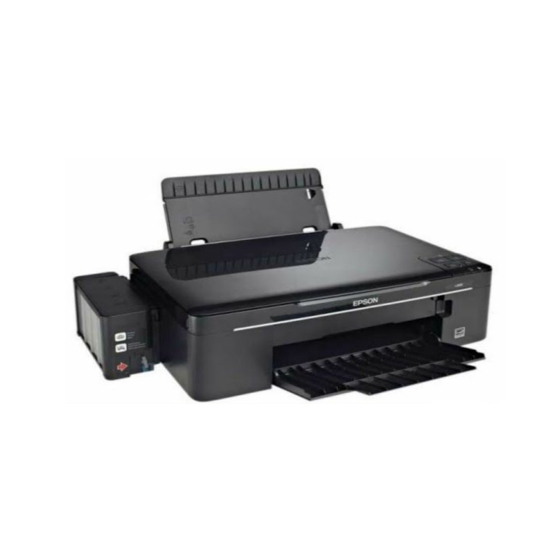
Epson L200 Service Manual

Epson L200 Service Manual

Color inkjet printer
Hide thumbs Also See for L200:

Advertisement

SERVICE MANUAL
Color Inkjet Printer
L200/L201
L100/L101
CONFIDENTIAL
SEMF10-001

Advertisement

Table of Contents
loading

Summary of Contents for Epson L200

  • Page 1 SERVICE MANUAL Color Inkjet Printer L200/L201 L100/L101 CONFIDENTIAL SEMF10-001...
  • Page 2 SEIKO EPSON would greatly appreciate being informed of them. The contents of this manual are subject to change without notice. The above not withstanding SEIKO EPSON CORPORATION can assume no responsibility for any errors in this manual or the consequences thereof.
  • Page 3: Safety Precautions

    Strictly observe the following cautions. Failure to comply may lead to personal injury or damage of the product. 1. Repairs on Epson product should be performed only by an Epson certified repair technician. 2. No work should be performed on this product by persons unfamiliar with basic safety knowledge required for electrician.
  • Page 4 8. When disassembling or reassembling this product, make sure to wear gloves to avoid injuries from metal parts with sharp edges. 9. Use only recommended tools for disassembling, reassembling or adjusting the printer. 10. Observe the specified torque when tightening screws. 11.
  • Page 5: About This Manual

    About This Manual This manual, consists of the following chapters, is intended for repair service personnel and includes information necessary for properly performing maintenance and servicing the product. CHAPTER 1. DISASSEMBLY / REASSEMBLY Describes the disassembly/reassembly procedures for main parts/units of the product, and provides the standard operation time for servicing the product.
  • Page 6 Revision Status Revision Date of Issue Description October 8, 2010 First Release Confidential...
  • Page 7: Table Of Contents

    L200/L201/L100/L101 Revision A Contents Chapter 1 Disassembly/Reassembly 1.1 Overview ................................... 9 1.1.1 Tools ................................. 9 1.1.2 Checks and precautions before disassembling ....................10 1.1.3 Protection for Transportation.......................... 12 1.2 Disassembly/Reassembly Procedures ........................14 1.2.1 Standard Operation Time for servicing the product ..................15 1.2.2 Disassembling/Reassembling Flowchart......................
  • Page 8: Chapter 1 Disassembly/Reassembly

    CHAPTER 1 DISASSEMBLY/REASSEMBLY Confidential...
  • Page 9: Overview

    L200/L201/L100/L101 Revision A 1.1 Overview This chapter describes procedures for disassembling the main parts/units of L200/L201/L100/L101. Unless otherwise specified, disassembled parts/units can be reassembled by reversing the disassembly procedure. See the cautions or tips for disassembly/reassembly described in “ 1.3 Details of Disassembling/Reassembling by Parts/Unit (p23)”.
  • Page 10: Checks And Precautions Before Disassembling

    Revision A 1.1.2 Checks and precautions before disassembling Ink may spill when removing the following parts from L200/L201/L100/L101. This section describes the parts that may cause ink spill and the means to minimize the ink spill when removing the parts.
  • Page 11 L200/L201/L100/L101 Revision A Means do to minimize the ink spill Even observing the points described in this section, ink may spill in the following situations. Therefore, be careful not to contaminate the inside of the printer or its surroundings by preparing the container to receive the leaked ink, or the like.
  • Page 12: Protection For Transportation

    L200/L201/L100/L101 Revision A 1.1.3 Protection for Transportation Before packing the printer for returning it to the user, secure it at the specified points with strong tape to avoid damaging the printer or ink leakage during transport, and make sure to check the points as follows.
  • Page 13 L200/L201/L100/L101 Revision A Points to be checked before packing the printer The Valve Lever is on the position shown below All the caps of the Ink Supply Tank Assy are (the Choke Valve is closed). (See Figure 1-2.) securely closed.
  • Page 14: Disassembly/Reassembly Procedures

    L200/L201/L100/L101 Revision A 1.2 Disassembly/Reassembly Procedures This section describes procedures for disassembling the parts/units in a flowchart format. For some parts/units, detailed procedures or precautions are provided (accordingly indicated by icons and cell's color). Refer to the explanations in the example chart below and perform an appropriate disassembling and reassembling procedure.
  • Page 15: Standard Operation Time For Servicing The Product

    The following are the standard operation time for servicing the product. Those are based on the MTTR result measured using a prototype. The underlined parts/units are supplied as After Service Parts. Standard Operation Time for servicing L200/L201: Table 1-2. Standard Operation Time for servicing L100/L101: Table 1-3.
  • Page 16 L200/L201/L100/L101 Revision A Table 1-2. Standard Operation Time (L200/L201) Time (second) Time (second) Parts/Unit Parts/Unit Replace- Adjust- Replace- Adjust- Total Total ment ment ment ment PF Roller Left Cover PF Motor Ink Supply Tank Assy Ink Tube Guide 1st Ink Tube Guide 2nd...
  • Page 17 L200/L201/L100/L101 Revision A Table 1-3. Standard Operation Time (L100/L101) Time (second) Time (second) Parts/Unit Parts/Unit Replace- Adjust- Replace- Adjust- Total Total ment ment ment ment Pick Assy CR Front Waste Ink Pads Top Cover (under the Cap Assy) Pump Assy...
  • Page 18: Disassembling/Reassembling Flowchart

    Label Label (p 29) (p 27) (p 28) (p 29) (p 29) (p 29) Ink Supply Holder Assy L200/L201 specific parts/unit (p 29) (p 29) L100/L101 specific parts/unit Middle Housing Assy Common parts/unit Screw type/torque list Symbol Screw type Torque ±...
  • Page 19 “ Flowchart 1-1 Disassembling Flowchart of Housing Part (1) ± C.F.B-TITE SCREW 2.6x6 0.25 kgf·cm (p18)” for disassembly of the Housing Part of L200/L201. C.B.P TITE SCREW 2.5x5 5.0 ~ 6.0 kgf·cm C.B.P TITE SCREW 3x6 5.0 ~ 6.0 kgf·cm C.B.P TITE SCREW 2.6x16...
  • Page 20: Printer Mechanism Part

    (under the Cap Assy) (p 31) (p 40) CR Cover Screw Tube Holder Top/ Tube Holder Lower L200/L201 specific parts/unit Adapter Assy L100/L101 specific parts/unit Ink Tube Guide Main Frame Common parts/unit EJ Frame Assy (p 22) Screw type/torque list...
  • Page 21 FFC Cover CR Front Holder Contact Tube Assy (p 26) (p 24) (p 27) (p 28) (p 34) L200/L201 specific parts/unit Bracket Pump Roller Pump L100/L101 specific parts/unit FFC Cover Common parts/unit (p 26) (p 26) Printhead Screw type/torque list...
  • Page 22 PCB Encoder Head FFC Timing Belt Valve Assy (p 39) (p 34) (p 32) Cover Flushing (p 28) L200/L201 specific parts/unit Carriage L100/L101 specific parts/unit Common parts/unit Waste Ink Pads Ink Supply Tank (p 25) (p 31) (for flushing) Assy...
  • Page 23: Details Of Disassembling/Reassembling By Parts/Unit

    L200/L201/L100/L101 Revision A Details of Disassembling/Reassembling by Parts/Unit Panel Unit (L200/L201) Document Pad (L200/L201) Scanner Unit (L200/L201) Document Cover Scanner Unit Panel Unit Document Pad Scanner FFC Panel FFC Scanner Motor cable Panel FFC Scanner Unit Origin Position Standard line Double-sided tape C.B.P-TITE SCREW 3x10 (5.0 ±...
  • Page 24 L200/L201/L100/L101 Revision A Power Supply Unit FFC Cover Cap Unit Step 1 Step 2 Cap Unit Head FFC Cleaner Case Spring Waste Ink Tube Point A Frame Base Hook Dowel for temporarily secure Groove Hole Step 3 Step 4 Cap Unit...
  • Page 25 L200/L201/L100/L101 Revision A LD Roller Assy / LD Roller Housing Buckler Step 1 Step 2 Friction Buckler Sheet BF2-A Gear 23T Double-sided tape LD Roller Assy LD Roller LD Roller Assy Friction Buckler R Friction Buckler Shaft Gear 24T Housing Bucklers...
  • Page 26 L200/L201/L100/L101 Revision A Gear Pump Idle/ Gear Pump/ Bracket Pump/ Roller Pump/ Waste Ink Tube/ Pump Housing Pump Assy Waste Ink Tray Assy Step 1 Cap Unit side Waste Ink Tray Assy side Waste Ink Tube Waste Ink Tube ±...
  • Page 27 L200/L201/L100/L101 Revision A Right Cover / Left Cover / Bottom Cover CR Front CR Cover CR Cover Right Cover Left Cover C.B.P-TITE SCREW 2.5x5 (5.0 ~ 6.0 kgf·cm) Carriage Bottom Cover CR Front Carriage C.B.P-TITE SCREW 2.5x5 (5.0 ~ 6.0 kgf·cm)
  • Page 28 Assy side side 190 ± 1 mm 165 ± 1 mm Cyan 257 ± 1 mm L200/L201: 310 mm L100/L101: 290 mm 335 ± 1 mm Valve case Ink Tube 420 ± 4.2 mm or 10% tolerance Ink Supply Tank Assy...
  • Page 29 3. Insert the section A of the Tube Guide Plate Support into the hole C of the Tube Guide Plate Support up from the bottom as shown in the “OK” above. above. image above to secure it Middle Housing (L200/L201) Ink Supply Holder Assy (L200/L201) Ink Tube Guide 1st / Ink Supply Holder Assy (L200/L201) Ink Tube Guide 1st Ink Tube Guide 1st Holes Left side Middle Housing Middle Housing C.B.P-TITE SCREW 2.5x5...
  • Page 30 L200/L201/L100/L101 Revision A Upper Housing Assy / Ink Supply Holder Assy (L100/L101) Refilling Ink Label (L100/L101) Printer Cover (L100/L101) Left side Step 1 Bottom side Step 3 Upper Housing Assy Hook 10.0 mm 4.0 mm Ink Supply Holder Assy Hook 4.0 mm...
  • Page 31: Routing Ffcs/Cables

    L200/L201/L100/L101 Revision A 1.4 Routing FFCs/cables Scanner Unit /CIS (L200/L201) CR Motor Panel FFC Panel FFC Panel FFC CR Motor cable Rib A CR Motor Pick Assy Bottom of the Scanner Unit Pick Assy Ferrite Core Scanner FFC Ferrite Core...
  • Page 32 L200/L201/L100/L101 Revision A Head FFC PF Motor Step 1 Holder FFC Fold line PF Motor cable Ferrite Core CR Encoder Head FFC Step 3 Step 2 Main Frame Main Frame Holder FFC Holder FFC Hole PF Motor Head FFC Head FFC...
  • Page 33: Chapter 2 Adjustment

    CHAPTER 2 ADJUSTMENT Confidential...
  • Page 34: Required Adjustments

    L200/L201/L100/L101 Revision A 2.1 Required Adjustments When the EEPROM Data Copy cannot be made for the Main Board that needs to be replaced, the Waste Ink Tray Assy must be replaced after replacing the Main Board with a new one.
  • Page 35 L200/L201/L100/L101 Revision A Table 2-1. Required Adjustment List Priority Adjustment Item EEPROM   data copy Initial setting Maintenance counter reset Ink charge Head ID input Top margin adjustment Head angular adjustment Bi-D adjustment PF band adjustment To copy adjustment values or the...
  • Page 36: Details Of Adjustments

    L200/L201/L100/L101 Revision A 2.2 Details of Adjustments This section provides adjustment procedures for which explanation in details is necessary. See “ 2.1 Required Adjustments (p34)” for the adjustments not explained here. 2.2.1 TOP Margin Adjustment Three adjustment patterns are printed on the top of the paper as shown in Figure 2-1.
  • Page 37: Chapter 3 Maintenance

    CHAPTER 3 MAINTENANCE Confidential...
  • Page 38: Overview

    Before applying the grease, make sure to wipe off old grease completely with BEMCOT. Grease Type Name EPSON Part Code Supplier Grease G-45 (TBD) 1033657 (TBD) EPSON...
  • Page 39: Lubrication Points And Instructions

    Lubrication Point Lubrication Point Figure 3-2. Lubrication on Scanner Unit Figure 3-1. Lubrication on Paper Support Assy (L200/L201) <Lubrication Point> <Lubrication Point> 1. Ribs (x20) of the Contacting points (x5) 3.2 mm...
  • Page 40 L200/L201/L100/L101 Revision A <Lubrication Point> <Lubrication Point> <Lubrication Point> Contacting points (x2) Sliding surface between Ribs (x3) of the Frame with the Driven Pulley the Roller Idler Pick and Base (contacting points Spring Roller Idler Pick with the PF Roller) <Type>...
  • Page 41: Chapter 4 Appendix

    CHAPTER 4 APPENDIX Confidential...
  • Page 42: Power-On Sequence

    L200/L201/L100/L101 Revision A 4.1 Power-On Sequence This section describes the power-on sequences for this product. The preconditions are as follows. Condition Completing ink charge. No paper on the paper path. The Printhead is capped with the Cap of the Ink System.
  • Page 43 L200/L201/L100/L101 Revision A Table 4-1. Operation of the power-on sequence Carriage/PF roller Operation movement and position 4. Detecting ink cartridge and initializing ink system 4-1.The carriage moves to the 80-digit side for IES detection. 4-2.The carriage returns to its home position.
  • Page 44: Connector Diagram

    L200/L201/L100/L101 Revision A 4.2 Connector Diagram Cable connections of this printer are shown below. Scanner Unit Only L200/L201 CIS Module Printhead CR Motor Scanner Motor Panel Unit L200/L201 Panel Board CR Encoder J201 Panel Unit L100/L101 Main Board Panel Board...
  • Page 45: Troubleshooting

    L200/L201/L100/L101 Revision A 4.3 Troubleshooting This section describes the troubleshooting workflow and fatal error information. 4.3.1 Troubleshooting Workflow The following page describes the troubleshooting workflow. Follow the flow when troubleshooting problems. Appendix Troubleshooting Confidential...
  • Page 46 • PE Sensor Lever replacement • Ink tube connection is incomplete. ESK’s repair data on FY08 / FY09 models. [Major Troubleshooting] • Open valve • Ink tank replacement Printer Mechanism specification for L200/L201/L100/L101. Finish • Ink tube re-installation Appendix Troubleshooting Workflow Confidential...
  • Page 47: Fatal Error Code

    L200/L201/L100/L101 Revision A 4.3.2 Fatal Error Code This section describes the fatal error code and the possible cause for this product. Printer fatal error list Table 4-2. Fatal Error List (Printer) Error Error type Error name Possible cause code • CR Encoder failure (contaminated/detached scale, Encoder Board failure) •...

This manual is also suitable for:

L101L201L100

Table of Contents