Table of Contents
Advertisement
Available languages
Available languages
Harbor Breeze® is a registered trademark
of LF, LLC. All Rights Reserved.
Federal regulations require all ceiling fans with light kits manufactured
or imported after January 1, 2009, to limit total wattage consumed by the
light kit to 190W. Therefore, this fan is equipped with a wattage limiting
device.
Questions, problems, missing parts? Before returning to your retailer, call our customer
service department at 1-800-527-1292, 8:30 a.m.-5 p.m., CST,
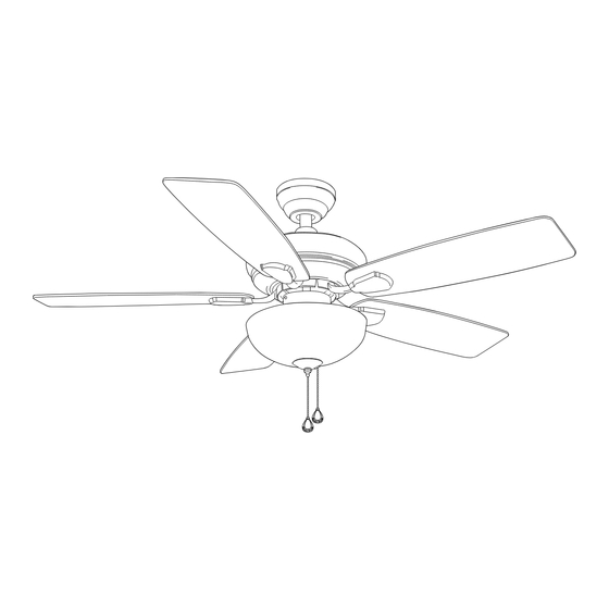
CEDAR HILL CEILING FAN
MODEL #E-PEN44BCW5MC
Monday-Friday.
1
ITEM #0312114
español p. 20
E206035
Advertisement
Chapters
Table of Contents

Related Manuals for Harbor Breeze CEDAR HILL


Summary of Contents for Harbor Breeze CEDAR HILL
- Page 1 ITEM #0312114 CEDAR HILL CEILING FAN MODEL #E-PEN44BCW5MC Harbor Breeze® is a registered trademark of LF, LLC. All Rights Reserved. español p. 20 Federal regulations require all ceiling fans with light kits manufactured or imported after January 1, 2009, to limit total wattage consumed by the light kit to 190W.
-
Page 2: Table Of Contents
TABLE OF CONTENTS Safety Information ..…………………………………………………………………………...……..….3 Package Contents ..…………………………………………………………………..……..…..…..4 Hardware Contants ........................5 Preparation ..….…………………..……………………….…………….………………..6 Initial Installation ....……………………...………………………………….....6 - 7 Downrod Style Fan Mounting ...…………………………..……………..……......8 - 9 Closemount Style Fan Mounting ……………………....…..……………………..9 - 10 Wiring ................………………………....10 - 12 Final Installation ………….…………….……………………….…………..…....12 - 15 Fan Operation ..............………………………………...15 - 16 Care and Maintenance ..……………………………………………………………….......16... -
Page 3: Safety Information
SAFETY INFORMATION READ AND SAVE THESE INSTRUCTIONS Please read and understand this entire manual before attempting to assemble, install or operate the product. If you have any questions regarding the product, please call customer service at 1-800-527-1292, 8:30 a.m.-5:00 p.m., CST, Monday-Friday. 1. -
Page 4: Package Contents
PACKAGE CONTENTS Part Description Quantity Downrod Canopy Mounting Bracket (pre-attached to canopy) Yoke Cover Motor Housing Switch Housing Cap (pre-attached to motor housing) Glass Shade Blade Arm Blade Pull Chain Extension (in hardware pack) Light Kit Fitter Finial Plate (pre-attached to light kit fitter) Finial (pre-attached to light kit fitter) Candelabra Base Bulb Canopy Cover (pre-attached to canopy) -
Page 5: Hardware Contants
HARDWARE CONTENTS Part Description Quantity Part Shown to Size Motor Screw (10 in motor; 1 in hardware pack) 3/16 Blade Screw (in hardware pack) 5.4M/M Lock Washer (10 in motor; 1 attached to motor screw in hardware pack) Blade Washer (in hardware pack) E3 Wire Connector (in hardware pack) Canopy Mounting Screw (attached to mounting bracket) -
Page 6: Preparation
PREPARATION 1. Before beginning assembly, installation or operation of product, make sure all parts are present. Compare parts with package contents list and diagram above. If any part is missing or damaged, do not attempt to assemble, install or operate the product. Estimated Assembly Time: 120 minutes Tools Required for Assembly (not included): electrical... - Page 7 INITIAL INSTALLATION Fig. 3 3. Check to make sure blades (I) are at least 30 in. from any obstruction and at least 7 ft. above the floor. (Fig. 3) 30 in. min. 7 ft. min. Fig. 4A Fig. 4B 4. Loosen canopy mounting screws (FF) in slotted holes in canopy (B) and remove the other two screws (FF)--save screws (FF) for later use.
-
Page 8: Downrod Style Fan Mounting
DOWNROD STYLE FAN MOUNTING 1. Remove pin (GG) and clip (HH) from Fig. 1A Fig. 1B downrod (A). (Fig. 1A) Partially loosen set screws in motor housing yoke at top of motor housing (E). (Fig. 1B) Screw *Helpful Hint: Downrod style mounting is best suited for ceilings 8 ft. -
Page 9: Closemount Style Fan Mounting
DOWNROD STYLE FAN MOUNTING Fig. 4 4. Depending on the length of downrod (A) you use, you may need to cut the lead wires back to simplify the wiring. If you decide to cut back the lead wires, it is suggested that you do so in the following manner: Ball Take the lead wires and make sure that you have pulled... -
Page 10: Wiring
CLOSEMOUNT STYLE FAN MOUNTING Fig. 2 2. Pull wires through hole in the middle of the canopy (B) and attach canopy (B) to motor housing (E) using the three screws (KK) and three lock washers (LL) provided. (Fig. 2) Hardware Used 3/16 X 11 mm Screw 5 mm Lock Washer Fig. - Page 11 WIRING 1. Choose wiring diagram (Fig. 1A, Fig. 1B or Fig. 1C) that fits your situation and make appropriate FAN AND LIGHT CONTROLLED BY PULL CHAINS wiring connections as follows: [NOTE: For each wire Fig. 1A BLACK connection below, and on the following page, use 120 V Power WHITE FROM...
-
Page 12: Final Installation
WIRING 2. Wrap electrical tape around each individual Fig. 2 wire connector (EE) down to the wire as shown in Fig. 2. WARNING: Make sure no bare wire or wire strands are visible after making connections. Place green and white connections on opposite side of box from the black and blue (if applicable) connections. - Page 13 FINAL INSTALLATION Fig. 2 2. Partially insert three blade screws (BB), along with three blade washers (DD), to attach one blade arm (H) to a blade (I). Then, tighten each blade screw (BB) starting with the one in the middle. (Fig. 2) Repeat with remaining blades (I).
- Page 14 FINAL INSTALLATION Fig. 5A Fig. 5B 5. Punch center cap out of switch housing cap (F) with a screwdriver. (Fig. 5A) Remove hex nut (II) and lock washer (JJ) from threaded rod at top of light kit fitter (K). Remove Center finial (M), finial plate (L) and white washer from White...
-
Page 15: Fan Operation
FINAL INSTALLATION 9. Place white washer, that was removed on previous page Fig. 9 in Step 5, inside glass shade (G) over center hole. Align center hole in the glass shade (G) with threaded rod in light kit fitter (K), allowing pull chains to come through corresponding holes in glass shade (G). -
Page 16: Care And Maintenance
FAN OPERATION Fig. 3 3. Use the fan reverse switch, located on the switch housing, to optimize your fan for seasonal performance. Switch Housing (Fig. 3) A ceiling fan will allow you to raise your thermostat setting in summer and lower your thermostat setting in winter without feeling a difference in your comfort. -
Page 17: Troubleshooting
TROUBLESHOOTING WARNING: Before beginning work, shut off the power supply to avoid electrical shock. Problem Possible Cause Corrective Action Fan does not move. 1. Reverse switch not engaged. 1. Push switch firmly either up or down. 2. Power is off or fuse is blown. 2. -
Page 18: Warranty
TROUBLESHOOTING Problem (cont.) Possible Cause (cont.) Corrective Action (cont.) [Fan operates but lights 5. Light kit is lamped with more 5. Lamp light kit with more than fail (if applicable).] than the bulbs allowable 190W, that total no 190W. causing the wattage limiting device to interrupt the flow of electricity to the light kit. -
Page 19: Replacement Parts List
REPLACEMENT PARTS LIST For replacement parts, call our customer service department at 1-800-527-1292, 8:30 a.m.-5:00 p.m., CST, Monday-Friday. When ordering parts, please have the Model # or Item # of the fan available, which can be found on page 1. The following parts are replaceable: Part Description... - Page 20 ARTICULO #0312114 VENTILADOR DE TECHO CEDAR HILL MODELO #E-PEN44BCW5MC Harbor Breeze® is a registered trademark of LF, LLC. All Rights Reserved. El reglamento federal requiere que cualquier ventilador de techo con juego de luz fabricado o importado después del 1 ro de enero del 2009 limite el vatiaje total que consume el juego de luz a 190W.
- Page 21 INDICE DE MATERIAS Información de seguridad ..……………………………………………......22 Contenido del paquete ....………………………………………………………..23 Contenido de artículos de ferretería ..................24 Preparación ..........….…………………..………………....25 Instalación inicial ..........……………………………………..25 - 27 Estilo de montaje del ventilador con el vástago ..........……………27 - 28 Estilo de montaje del ventilador sin el vástago ..........……...29 - 30 Conexión de los cables .........…………………………………….30 - 32...
-
Page 22: Información De Seguridad
INFORMACION DE SEGURIDAD POR FAVOR LEA Y GUARDE ESTAS INSTRUCCIONES Por favor lea el instructivo entero antes de tratar de ensamblar, instalar o hacer funcionar el producto. Si tiene alguna pregunta acerca del producto, por favor llame al servicio al cliente al 1-800-527-1292, de 8:30 a.m. -
Page 23: Contenido Del Paquete
CONTENIDO DEL PAQUETE Pieza Descripción Cantidad Vástago Cubierta Soporte de montaje (sujetado de antemano a la cubierta) Cubierta del yugo Bastidor del motor Cubierta de la caja del interruptor (sujetada de antemano al bastidor del motor) Pantalla de vidrio Brazo para la paleta Paleta Extensión para la cadena de encendido (en paquete de artículos de ferretería) -
Page 24: Contenido De Artículos De Ferretería
CONTENIDO DE ARTICULOS DE FERRETERIA Se muestra la pieza Pieza Descripción Cantidad en tamaño natural Tornillo del motor (10 en el motor; 1 en el paquete de artículos de ferretería) Tornillo para la paleta 4,76 mm (en paquete de artículos de ferretería) Arandela de seguridad 5,4 M/M (10 en el motor;... -
Page 25: Preparación
PREPARACION 1. Antes de empezar con el ensamblaje e instalación del producto, asegúrese de tener todas las piezas. Compare las piezas con la lista y los diagramas del "Contenido del paquete" en la página anterior. Si falta alguna pieza o se encuentra dañada, no trate de ensamblar, instalar o hacer funcionar el producto. - Page 26 INSTALACION INICIAL Fig. 2 2. Determine el método de montaje. (Fig. 2) A. Montaje con el vástago (techo normal o en ángulo) B. Montaje sin el vástago (sólo techo normal) Importante: Cuando use el montaje en ángulo, asegúrese de que el ángulo del techo no tenga una inclinación mayor de 19°.
-
Page 27: Estilo De Montaje Del Ventilador Con El Vástago
INSTALACION INICIAL 5. Saque los tornillos del motor (AA) y las Fig. 5 arandelas de seguridad (CC) del lado inferior del motor y guárdelos para sujetar los brazos para las paletas (H) más adelante. [Si hay también soportes de plástico del motor instalados con los tornillos del motor (AA) y las arandelas de seguridad (CC), deséche los soportes de plástico.] (Fig. - Page 28 ESTILO DE MONTAJE DEL VENTILADOR CON EL VASTAGO Fig. 3 3. Coloque el vástago (A) dentro del yugo del bastidor del motor, alinee los agujeros y vuelva a instalar la clavija (GG) y el sujetador (HH). Vuelva a ajustar los tornillos de fijación en el yugo del tornillo de bastidor del motor y luego apriete las tuercas.
-
Page 29: Estilo De Montaje Del Ventilador Sin El Vástago
ESTILO DE MONTAJE DEL VENTILADOR CON EL VASTAGO Fig. 6 6. Instale el extremo de la bola del vástago (A) en la abertura del soporte de montaje (C). Alinee la ranura de la bola con la lengüeta del soporte de montaje (C). (Fig. 6) PELIGRO: El no alinear la lengüeta con la ranura de la bola puede ser causa de graves bola... -
Page 30: Conexión De Los Cables
ESTILO DE MONTAJE DEL VENTILADOR SIN EL VASTAGO Fig. 3 3. Cuelgue el bastidor del motor (E) en la lengüeta en el soporte de montaje (C) usando uno de los agujeros sin ranura en la cubierta (B). (Fig. 3) lengüeta CONEXION DE LOS CABLES ADVERTENCIA: Para reducir el riesgo de incendio, choque eléctrico o daño corporal, los conectores para cable... - Page 31 CONEXION DE LOS CABLES VENTILADOR CONTROLADO POR CADENA DE 1B. VENTILADOR CONTROLADO POR CADENA ENCENDIDO, LUZ POR INTERRUPTOR DE PARED DE ENCENDIDO, LUZ POR INTERRUPTOR DE Fig. 1B NEGRO PARED: Si usted piensa controlar la luz del 120 V cables NEGRO (INTERUPTOR DE PARED) de corriente DEL TECHO...
-
Page 32: Instalación Final
CONEXION DE LOS CABLES Fig. 3 IMPORTANTE: El usar un interruptor con reductor de luz de gama completa para controlar la velocidad del ventilador causará un zumbido recio en el ventilador. Para reducir el riesgo de incendio o choque eléctrico, NO use un interruptor con reductor de luz de gama completa para controlar la velocidad del ventilador. - Page 33 INSTALACION FINAL Fig. 3 3. Introduzca dos tornillos del motor (AA), junto con las arandelas de seguridad (CC), en uno de los brazos para la paleta (H) para sujetar el brazo para la paleta (H) al motor. Apriete bien los tornillos del motor (AA).
- Page 34 INSTALACION FINAL 6. Con cuidado pase los cables del conectador para Fig. 6 el juego de luz (K) por el agujero de en medio de la cubierta de la caja del interruptor (F). Atornille la caja del interruptor cubierta de la caja del interruptor (F) en la varilla conexiones tipo “molex”...
-
Page 35: Funcionamiento Del Ventilador
INSTALACION FINAL 9. Coloque la arandela blanca, que se quitó en el Fig. 9 paso 5 de esta sección, dentro de la pantalla de vidrio (G) encima del agujero de en medio. Alinee el agujero de en medio de la pantalla de vidrio (G) con la varilla roscada del conectador para el juego de luz (K), dejando que las cadenas de encendido pasen arandela... -
Page 36: Cuidado Y Mantenimiento
FUNCIONAMIENTO DEL VENTILADOR Fig. 2 2. La cadena de encendido de en medio se usa para ENCENDER o APAGAR la luz. (Fig. 2) Fig. 3 3. Use el interruptor de reversa, localizado en la caja del interruptor, para optimizar el uso del ventilador durante las caja del interruptor estaciones. -
Page 37: Localización De Fallas
LOCALIZACION DE FALLAS Advertencia: Antes de empezar cualquier trabajo, corte el suministro de electricidad para evitar un choque eléctrico. Problema Causa posible Acción correctiva El ventilador no se 1. El interruptor de reversa no está 1. Mueva el interruptor firmemente mueve. - Page 38 LOCALIZACION DE FALLAS Problema Causa posible Acción correctiva [El ventilador funciona 2. No se conectaron correctamente 2. Verifique que se conectaron pero la luz no (si aplica).] los cables en la cubierta (B). bien los cables en la cubierta (B) y, si es necesario, vuelva a conectarlos según las instruccion- es en las páginas 31 y 32.
-
Page 39: Garantía
GARANTIA GARANTIA LIMITADA DE POR VIDA: Litex Industries garantiza que este ventilador está libre de defectos de mano de obra y de materiales desde la fecha de salida de la fábrica por el tiempo de por vida limitada a partir de la fecha de compra. Esta garantía sólo se aplica al comprador original. -
Page 40: Lista De Piezas De Repuestos
LISTA DE PIEZAS DE REPUESTO Para piezas de repuesto, llame a nuestro departamento de servicio al cliente al 1-800-527-1292, de 8:30 a.m. a 5:00 p.m., hora central, de lunes a viernes. Al pedir piezas, por favor tenga listo el No. de modelo o No.
Need help?
Do you have a question about the CEDAR HILL and is the answer not in the manual?
Questions and answers