Table of Contents
Advertisement
Available languages
Available languages
Harbor Breeze® is a registered trademark
of LF, LLC. All Rights Reserved.
ATTACH YOUR RECEIPT HERE
Serial Number
Questions, problems, missing parts? Before returning to your retailer, call our customer
service department at 1-800-643-0067, 8 a.m. - 6 p.m., EST, Monday - Thursday, 8 a.m. - 5 p.m.,
EST, Friday.
EB1550
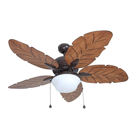
WAVEPORT STYLE CEILING
Purchase Date
1
ITEM #0648635
MODEL #E-WK52NWZ5C1
Español p. 22
For
Damp Location
Lowes.com/harborbreeze
FAN
Advertisement
Chapters
Table of Contents

Related Manuals for Harbor Breeze WAVEPORT STYLE E-WK52NWZ5C1


Summary of Contents for Harbor Breeze WAVEPORT STYLE E-WK52NWZ5C1
- Page 1 ITEM #0648635 WAVEPORT STYLE CEILING MODEL #E-WK52NWZ5C1 Harbor Breeze® is a registered trademark of LF, LLC. All Rights Reserved. Español p. 22 Damp Location ATTACH YOUR RECEIPT HERE Serial Number Purchase Date Questions, problems, missing parts? Before returning to your retailer, call our customer service department at 1-800-643-0067, 8 a.m.
-
Page 2: Table Of Contents
TABLE OF CONTENTS Safety Information ......................... 2 Package Contents ........................ 4 Hardware Contents ........................... 5 Preparation ........................... 5 Initial Installation ........................5 Downrod-Style Fan Mounting ....................7 Closemount-Style Fan Mounting ................... 9 Wiring ...........................11 Final Installation ........................13 Installing Fan Without Light Kit ................... 16 Operating Instructions ...................... - Page 3 SAFETY INFORMATION DANGER When mounting fan to a ceiling outlet box, use a METAL octagonal outlet box; do NOT use a plastic outlet box. Make sure the outlet box is securely attached to the building structure and can support the full weight of the fan. The outlet box and its support must be able to support the moving weight of the fan (at least 35 lbs.).
-
Page 4: Package Contents
PACKAGE CONTENTS PART DESCRIPTION PART DESCRIPTION QUANTITY QUANTITY Pin (preassembled) Downrod Clip (preassembled) Canopy Cap (preassembled) Mounting Bracket (preassembled) Hex Nut (preassembled) Motor Housing Lock Washer (preassembled) Yoke Cover Bulb Light Kit Fitter Motor Washer (preassembled) Blade Light Kit Fitter Screw Blade Arm (preassembled) Glass Shade... -
Page 5: Hardware Contents
HARDWARE CONTENTS (shown actual size) Rubber Blade Screw Blade E3 Wire Washer Connector Qty. 15 Qty. 15 + 1 extra Qty. 4 + 1 extra Pull Chain Extension Qty. 2 PREPARATION Before beginning assembly of product, make sure all parts are present. Place motor on carpet or on foam to avoid damage to finish. - Page 6 INITIAL INSTALLATION 2. Determine mounting method to use. A. Downrod-style mount (standard or angled 19° max. ceiling) B. Closemount-style (standard ceiling only) IMPORTANT: If using the angle mount, check to make sure the ceiling angle is not steeper than 19°. *Helpful Hint: Downrod-style mounting is best suited for ceilings 8 ft.
-
Page 7: Downrod-Style Fan Mounting
INITIAL INSTALLATION Secure mounting bracket (C) to outlet box (not STANDARD MOUNT ANGLE MOUNT included) using screws, spring washers and flat washers provided with the outlet box. *NOTE: It is very important you use the proper hardware when installing the mounting bracket (C) as this will support the fan. - Page 8 DOWNROD-STYLE FAN MOUNTING Insert downrod (A) through canopy (B), and yoke cover (E). Thread wires from motor housing (D) up through downrod (A). Slip downrod (A) into yoke, align holes and re-install pin (L) and clip (M). Tighten downrod (A) set screws and then tighten nuts.
-
Page 9: Closemount-Style Fan Mounting
DOWNROD-STYLE FAN MOUNTING If you cut back the lead wires in Step 4, strip 1/2 in. of insulation from end of of each wire -- white, black, green and blue (if applicable). Twist stripped ends of each strand of wire within the insulation with pliers (not included). - Page 10 CLOSEMOUNT-STYLE FAN MOUNTING Remove every other motor screw (J) and motor washer (R) from top of motor housing (D). Pull wires up through hole in the middle of the canopy (B) and attach canopy (B) to motor housing (D) using the three motor screws (J) and motor washers (R) previously removed.
-
Page 11: Wiring
WIRING WARNING: To reduce the risk of fire, electrical shock or personal injury, wire connectors provided with this fan are designed to accept only one 12-gauge house wire and two lead wires from the fan. If your house wire is larger than 12-gauge or there is more than one house wire to connect to the corresponding fan lead wires, consult an electrician for the proper size wire connectors to use. - Page 12 WIRING 1b. FAN CONTROLLED BY PULL CHAIN, LIGHT FAN CONTROLLED BY PULL CHAIN, LIGHT BY WALL SWITCH FAN AND LIGHT CONTROLLED BY TWO WALL SWITCHES BY WALL SWITCH: Connect BLACK wire from fan to BLACK wire from ceiling. Connect BLUE wire 120V POWER from fan to the BLACK wire from the independent FROM CEILING...
-
Page 13: Final Installation
FINAL INSTALLATION 1. Lift canopy (B) to mounting bracket (C) again, aligning slotted holes in canopy (B) with loosened canopy mounting screws (K) in mounting bracket Downrod Closemount (C). Twist canopy (B) clockwise to lock. Re-insert Option Option the two canopy mounting screws (K) previously removed (Step 4a, page 6) and tighten all canopy mounting screws (K) securely. - Page 14 FINAL INSTALLATION To install the fan with the light kit, remove preassembled hex nut (O) and lock washer (P) from Molex threaded rod at top of light kit fitter (F). Punch center Connections cap (N) out of switch housing (T) with a screwdriver (not included).
- Page 15 FINAL INSTALLATION Install bulbs (Q). CAUTION: When replacing bulb(s), allow bulb(s) and glass shade to cool down before touching. Thread preassembled fan and light pull chains through corresponding pull chain guides on the outer rim of the light kit fitter (F). Remove three light kit fitter screws (S) from light kit fitter (F).
-
Page 16: Installing Fan Without Light Kit
INSTALLING FAN WITHOUT LIGHT KIT 1. If you do NOT wish to use the light kit, remove the three preassembled switch housing screws (U) from preassembled switch housing plate on motor housing (D). Connect male plug from motor housing (D) to female plug from switch housing (T), matching up the colors on the male plug with the colors on the Male Switch... -
Page 17: Operating Instructions
OPERATING INSTRUCTIONS The fan pull chain labled FAN has four positions to control fan speed. One pull is HIGH, two is MEDIUM, three is LOW and four turns the fan OFF. If applicable, the light pull chain labled LIGHT is used to turn the light ON or OFF. -
Page 18: Care And Maintenance
OPERATING INSTRUCTIONS 3a. In warmer weather, setting the reverse switch in the LEFT position will result in downward airflow creating a wind chill effect. 3b. In cooler weather, setting the reverse switch in the RIGHT position will result in upward airflow that can help move stagnant, hot air off the ceiling area. -
Page 19: Troubleshooting
TROUBLESHOOTING WARNING: Before beginning work, shut off the power supply to avoid electrical shock. PROBLEM POSSIBLE CAUSE CORRECTIVE ACTION Fan does not move. 1. Reverse switch not engaged. 1. Push switch firmly either left or right. 2. Power is off or fuse is blown. 2. -
Page 20: Limited Lifetime Warranty
TROUBLESHOOTING PROBLEM POSSIBLE CAUSE CORRECTIVE ACTION 4. Check that molex connections 4. Wires in light kit fitter not wired in light kit fitter are connected correctly. properly according to instructions on page 14. 5. Lamp light kit with bulbs that 5. -
Page 21: Replacement Parts List
Monday - Thursday, 8 a.m. - 5 p.m., EST, Friday. PART DESCRIPTION PART# Downrod 0648635-A Canopy 0648635-B Mounting Bracket 0648635-C Light Kit Fitter 0648635-F Blade 0648635-G Blade Arm 0648635-H Switch Housing 0648635-T Printed in China Harbor Breeze® is a registered trademark of LF, LLC. All Rights Reserved. Lowes.com/harborbreeze LSLI1515... -
Page 22: Ventilador De Techo
ARTÍCULO # 0648635 VENTILADOR DE TECHO ESTILO WAVEPORT MODELO # E-WK52NWZ5C1 ® Harbor Breeze es una marca registrada de LF, LLC. Todos los derechos reservados. Para lugares húmedos ADJUNTE SU RECIBO AQUÍ Número de serie Fecha de compra ¿Preguntas, problemas, piezas faltantes? Antes de volver a la tienda, llame a nuestro Departamento de Servicio al Cliente al 1-800-643-0067, de lunes a jueves de 8 a.m. -
Page 23: Información De Seguridad
ÍNDICE Información de seguridad .....................23 Contenido del paquete ......................25 Aditamentos ..........................26 Preparación .......................... 26 Instalación inicial ........................26 Montaje del ventilador en estilo de varilla ................28 Montaje del ventilador en estilo cerrado ................30 Cableado ..........................32 Instalación final ........................34 Instalación del ventilador sin el kit de iluminación .............. - Page 24 INFORMACIÓN DE SEGURIDAD PELIGRO Cuando monte el ventilador en una caja de salida del techo, use una caja de salida octogonal de METAL; NO use una caja de salida de plástico. Asegúrese de que la caja de salida esté firmemente asegurada a la estructura de la construcción y que pueda sostener todo el peso del ventilador.
-
Page 25: Contenido Del Paquete
CONTENIDO DEL PAQUETE PIEZA DESCRIPCIÓN PIEZA DESCRIPCIÓN CANTIDAD CANTIDAD Pasador (preensamblado) Varilla Sujetador (preensamblado) Base Tapa (preensamblada) Soporte de montaje (preensamblada) Tuerca hexagonal (preensamblada) Carcasa del motor Arandela de seguridad Cubierta de la horquilla (preensamblada) Soporte del kit de iluminación Bombilla Aspa Arandela del motor... -
Page 26: Aditamentos
ADITAMENTOS (se muestran en tamaño real) Arandela para Tornillo para aspa aspa de goma Conector de cables E3 Cant.: 15 Cant.: 15 + 1 adicional + 1 adicional Cant.: 4 Extensión para la cadena de tiro Cant.: 2 PREPARACIÓN Antes de comenzar a ensamblar el producto, asegúrese de tener todas las piezas. Ubique el motor sobre una alfombra o espuma para evitar dañar el acabado. - Page 27 INSTALACIÓN INICIAL 2. Determine el método de instalación que utilizará. A. Montaje de varilla (techo estándar o en ángulo) 19° máx. B. Montaje cerrado (solo para techos estándar) IMPORTANTE: Si realiza la instalación en ángulo, verifique que el ángulo del techo no tenga una inclinación superior a los 19°.
-
Page 28: Montaje Del Ventilador En Estilo De Varilla
INSTALACIÓN INICIAL Asegure el soporte de montaje (C) a la caja MONTAJE ESTÁNDAR MONTAJE EN ÁNGULO de salida (no se incluye) con los tornillos, las arandelas de resorte y las arandelas planas que incluye la caja de salida. *NOTA: Es muy importante que use los aditamentos adecuados para instalar el soporte de montaje (C), ya que este soportará... - Page 29 MONTAJE DEL VENTILADOR EN ESTILO DE VARILLA Introduzca la varilla (A) a través de la base (B) y la cubierta de la horquilla (E). Pase los conductores desde la carcasa del motor (D) a través de la varilla (A). Deslice la varilla (A) en la horquilla, alinee los orificios y vuelva a instalar el pasador (L) y el sujetador (M).
-
Page 30: Montaje Del Ventilador En Estilo Cerrado
MONTAJE DEL VENTILADOR EN ESTILO DE VARILLA Si decidió cortar los cables conductores en el paso 4, pele 1,27 cm del aislamiento del extremo de cada cable: blanco, negro, verde y azul (si corresponde). Tuerza los extremos pelados de cada filamento de cable dentro del aislamiento con pinzas (no se incluyen). - Page 31 MONTAJE DEL VENTILADOR EN ESTILO CERRADO Retire los otros tornillos del motor (J) y la arandela del motor (R) de la parte superior de la carcasa del motor (D). Pase los cables hacia arriba a través del orificio en el centro de la base (B) y fije la base (B) a la carcasa del motor (D) con los tres tornillos del motor (J) y las arandelas del motor (R) retiradas anteriormente.
-
Page 32: Cableado
CABLEADO ADVERTENCIA: Para reducir el riesgo de incendios, descargas eléctricas o lesiones personales, los conectores de cables incluidos con este ventilador están diseñados para soportar solo un cable de la casa de calibre 12 y dos cables conductores del ventilador. Si el cable de la casa es de un calibre superior a 12 o hay más de un cable para conectar a los cables conductores del ventilador correspondientes, consulte a un electricista cuál es el tamaño adecuado de los conectores de cables que debe utilizar. - Page 33 CABLEADO 1b. VENTILADOR CONTROLADO POR VENTILADOR CONTROLADO POR CADENA DE TIRO Y LUZ CONTROLADA POR INTERRUPTOR DE PARED CADENA DE TIRO Y LUZ CONTROLADA POR INTERRUPTOR DE PARED: Conecte el cable NEGRO del ventilador al cable NEGRO ALIMENTACIÓN DE 120 V DESDE del techo.
-
Page 34: Instalación Final
INSTALACIÓN FINAL 1. Levante la base (B) hacia el soporte de montaje (C) nuevamente, alineando los orificios ranurados en la base (B) con los tornillos de montaje de la base (K) Opción de varilla Opción de montaje aflojados del soporte de montaje (C). Gire la base (B) cerrado en dirección de las manecillas del reloj para asegurar. - Page 35 INSTALACIÓN FINAL Para instalar el ventilador con el kit de iluminación, retire la tuerca hexagonal preensamblada (O) y las Conexiones arandelas de seguridad (P) de la varilla roscada de molex la parte superior del soporte del kit de iluminación (F). Perfore la tapa central (N) de la tapa de la carcasa del interruptor (T) con un destornillador (no se incluye).
- Page 36 INSTALACIÓN FINAL Instale las bombillas (Q). PRECAUCIÓN: Al reemplazar las bombillas, deje que estas y la pantalla de vidrio se enfríen antes de tocarlas. Enrosque las cadenas de tiro del ventilador y de la luz a través de las guías de cadena de tiro correspondientes en el borde exterior del soporte del kit de iluminación (F).
-
Page 37: Instalación Del Ventilador Sin El Kit De Iluminación
INSTALACIÓN DEL VENTILADOR SIN EL KIT DE ILUMINACIÓN 1. Si NO desea utilizar el kit de iluminación, retire los 3 tornillos preensamblados de la carcasa del interruptor (U) de la placa preensamblada de la carcasa del interruptor en la carcasa del motor (D). Conecte el enchufe macho de la carcasa del motor (D) al enchufe hembra de la carcasa del Enchufe... -
Page 38: Instrucciones De Funcionamiento
INSTRUCCIONES DE FUNCIONAMIENTO La cadena de tiro del ventilador marcada como FAN (ventilador) tiene cuatro posiciones para controlar la velocidad del ventilador. Jale una vez para la posición HIGH (alta); dos para la posición MEDIUM (media); tres para la posición LOW (baja);... -
Page 39: Cuidado Y Mantenimiento
INSTRUCCIONES DE FUNCIONAMIENTO 3a. En climas más cálidos la configuración del interruptor de reversa en la posición a la IZQUIERDA creará un flujo de aire descendente que generará un efecto de viento refrescante. 3b. En climas más fríos la configuración del interruptor de reversa en la posición a la DERECHA creará... -
Page 40: Solución De Problemas
SOLUCIÓN DE PROBLEMAS ADVERTENCIA: Antes de comenzar cualquier trabajo, desconecte el suministro de electricidad para evitar descargas eléctricas. PROBLEMA CAUSA POSIBLE ACCIÓN CORRECTIVA El ventilador no 1. El interruptor de reversa no está 1. Mueva firmemente el interruptor se mueve. activado. -
Page 41: Garantía Limitada De Por Vida
SOLUCIÓN DE PROBLEMAS PROBLEMA CAUSA POSIBLE ACCIÓN CORRECTIVA 4. Verifique que las conexiones molex 4. Los cables del soporte del kit de iluminación no están conectados en el soporte del kit de iluminación estén bien conectadas de acuerdo correctamente. con las instrucciones de la página 35. 5. -
Page 42: Lista De Piezas De Repuesto
Base 0648635-B Soporte de montaje 0648635-C Soporte del kit 0648635-F de iluminación Aspa 0648635-G Brazo del aspa 0648635-H Carcasa del interruptor 0648635-T Impreso en China Harbor Breeze ® es una marca registrada de LF, LLC. Todos los derechos reservados. Lowes.com/harborbreeze...
Need help?
Do you have a question about the WAVEPORT STYLE E-WK52NWZ5C1 and is the answer not in the manual?
Questions and answers
how do I pull the globe off to change the light bulbs?
To remove the globe (glass shade) on a Harbor Breeze WAVEPORT STYLE E-WK52NWZ5C1 ceiling fan:
1. Allow the bulb and glass shade to cool before touching.
2. Remove the three light kit fitter screws (S) from the light kit fitter (F).
3. Carefully lift the glass shade (I) away from the light kit fitter (F).
4. Do not remove the rubber ring on the edge of the glass shade.
5. To reattach, align the shade and hand-tighten the screws only—do not use tools.
This answer is automatically generated