Table of Contents
Advertisement
Available languages
Available languages
Harbor Breeze® is a registered trademark
of LF, LLC. All Rights Reserved.
Federal regulations require ceiling fans with light kits manufactured or imported after
January 1, 2009, to limit total wattage consumed by the light kit to 190W. Therefore,
this fan is equipped with a wattage limiting device.
ATTACH YOUR RECEIPT HERE
Serial Number
Questions, problems, missing parts? Before returning to your retailer, call or contact our
customer service department at 1-800-527-1292, 8:30 a.m. - 5:00 p.m., CST, Monday - Friday.
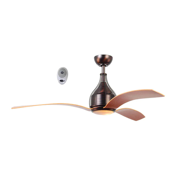
MONTE BELLO CEILING FAN
Purchase Date
1
ITEM #0219421
MODEL #E-ER56ORB3LKLR
Español p. 23
E192641
Advertisement
Chapters
Table of Contents

Subscribe to Our Youtube Channel
Related Manuals for Harbor Breeze E-ER56ORB3LKLR


Summary of Contents for Harbor Breeze E-ER56ORB3LKLR
- Page 1 ITEM #0219421 MONTE BELLO CEILING FAN Harbor Breeze® is a registered trademark MODEL #E-ER56ORB3LKLR of LF, LLC. All Rights Reserved. Español p. 23 Federal regulations require ceiling fans with light kits manufactured or imported after January 1, 2009, to limit total wattage consumed by the light kit to 190W. Therefore, this fan is equipped with a wattage limiting device.
-
Page 2: Table Of Contents
TABLE OF CONTENTS Safety Information ........................2 - 3 Product Overview ..........................4 Package Contents ........................... 5 Hardware Contents ......................... 6 Preparation ............................6 Initial Installation ........................7 - 8 Fan Mounting ..........................8 - 11 Wiring Remote Control and Fan .................... -
Page 3: Safety Information
SAFETY INFORMATION WARNINGS To reduce the risk of fire, electrical shock, or personal injury, mount fan to outlet box marked "ACCEPTABLE FOR FAN SUPPORT OF 35 LBS (15.9 KG) OR LESS" and use mounting screws provided with the outlet box. Most outlet boxes commonly used for the support of lighting fixtures are not acceptable for fan support and may need to be replaced. -
Page 4: Product Overview
Congratulations on your purchase of this Harbor Breeze® Ceiling Fan! This product has been specifically designed to give you all the performance you’ll ever need. Harbor Breeze® is the perfect fusion of smart innovation and beautiful style. Designed for more than just air movement, our products are built to function flawlessly... -
Page 5: Package Contents
PACKAGE CONTENTS 12V Size A23 PART DESCRIPTION QUANTITY PART DESCRIPTION QUANTITY Clip (preassembled) Downrod Canopy Mounting Screw Canopy (preassembled) Mounting Bracket Glass Shade Yoke Cover Shade Fitter Motor Housing Remote Control Blade Plate Transmitter Blade 12-volt Battery Light Kit Fitter Remote Control Receiver Canopy Cover Shade Fitter Screw... -
Page 6: Hardware Contents
HARDWARE CONTENTS (shown actual size) Lock Washer Blade E3 Wire Qty. 9 Screw Connector Qty. 9 Stop Qty. 10 Qty. 1 PREPARATION Before beginning assembly of product, make sure all parts are present. Compare parts with package contents list and hardware contents above. If any part is missing or damaged, do not attempt to assemble the product. -
Page 7: Initial Installation
INITIAL INSTALLATION Turn off circuit breakers and wall switch to the fan supply line leads. (Fig. 1) DANGER: Failure to disconnect power supply prior to installation may result in serious injury or death. Determine mounting method to use. (Fig. 2) A. -
Page 8: Fan Mounting
INITIAL INSTALLATION Secure mounting bracket (C) to outlet box using screws, spring washers, and flat washers provided with the outlet box. (Fig. 4) *NOTE: It is very important that you use the proper hardware when installing the mounting bracket (C) as this will support the fan. - Page 9 FAN MOUNTING Depending on the length of downrod (A) you use, you may need to cut the lead wires back to simplify the wiring. If you decide to cut back the lead wires, it is suggested that you do so in the following manner: Take the lead wires and make sure that you have pulled them all the way through the top of...
- Page 10 FAN MOUNTING 6. Slide yoke cover (D) onto downrod (A) followed by wire cage (V), canopy cover (I) and canopy (B). [Note: Canopy cover (I) must be turned with the shiny side toward the motor housing (E).] (Fig. 6) 7. Locate hanging ball (K) and stop pin (DD). Check inside of hanging ball (K) with finger to be sure surface is smooth;...
-
Page 11: Wiring Remote Control And Fan
FAN MOUNTING Install hanging ball (K) on downrod (A) into mounting bracket (C) opening. Align slot in hanging ball (K) with tab in mounting bracket (C). (Fig. 8) DANGER: Failure to align slot in hanging ball (K) with tab may result in serious injury or death. Hanging Ball Slot WIRING... - Page 12 WIRING 1. Make the necessary wiring connections for remote 120 V Power FROM CEILING control operation according to Fig. 1. For each wire connection, use one of the wire connectors (CC) BLACK WHITE ANTENNA provided, making sure to screw wire connector WHITE BLACK (CC) on in a clockwise direction.
-
Page 13: Final Installation
WIRING IMPORTANT: Using a full range dimmer switch (not included) to control fan speed will cause a loud humming noise from fan. To reduce the risk of fire or electrical shock, do NOT use a full range dimmer switch to control fan speed. (Fig. 4) Dimmer Speed Switch... - Page 14 FINAL INSTALLATION Place one blade plate (F) over blade (G), aligning holes, with numbered side in blade plate (F) facing up. After inserting one blade screw (AA), along with one lock washer (BB), through center hole in blade plate (F) and blade (G), align that blade Upward Arc screw (AA) with center hole in one set of three holes on underside of motor housing (E) to attach...
- Page 15 FINAL INSTALLATION 4. Remove one shade fitter screw (T) from post on underside of shade fitter (P) and loosen the other two shade fitter screws (T). (Fig. 4) Connect WHITE wire from motor housing (E) to WHITE wire from light kit fitter (H). Connect BLACK wire from motor housing (E) to BLACK wire from light kit fitter (H).
-
Page 16: Automated Learning Process/Activating Code
FINAL INSTALLATION Align openings in grooves of glass shade (O) with small protrusions on the inside of the shade fitter (P). Turn glass shade (O) to the right (clockwise) until it no longer turns. (Fig. 7) Make sure that glass shade (O) is turned completely to the right so that it is securely attached. -
Page 17: Changing Reverse Switch Setting
AUTOMATED LEARNING PROCESS/ACTIVATING CODE 2. Restore electrical power. Within 30 seconds of restoring electrical power, press the “ ” button on the front of the remote control transmitter (Q) for 5 seconds or until light on the fan blinks twice. (Fig. -
Page 18: Operation Instructions For Remote Control And Fan
OPERATION INSTRUCTIONS FOR REMOTE CONTROL AND FAN Operation buttons on the panel of the remote control transmitter (Q) (Fig. 1): button for fan HIGH speed button for fan MEDIUM speed button for fan LOW speed button for turning fan OFF button for light BRIGHTNESS and to turn light OFF... -
Page 19: Care And Maintenance
OPERATION INSTRUCTIONS FOR REMOTE CONTROL AND FAN 2A. In warmer weather, setting the reverse switch in the LEFT position will result in downward airflow creating a wind chill effect. (Fig. 2A) 2B. In cooler weather, setting the reverse switch in the RIGHT position will result in upward airflow that can help move stagnant, hot air off the ceiling area. -
Page 20: Troubleshooting
TROUBLESHOOTING If you have any questions regarding the product please call customer service at 1-800-527-1292, 8:30 a.m. - 5 p.m., CST, Monday - Friday. Warning: Before beginning work, shut off the power supply to avoid electrical shock. PROBLEM POSSIBLE CAUSE CORRECTIVE ACTION Fan does not move. -
Page 21: Warranty
TROUBLESHOOTING PROBLEM POSSIBLE CAUSE CORRECTIVE ACTION 5. Light kit is lamped with more than the 5. Lamp light kit with bulb that allowable 190W, causing the wattage totals no more than 190W. limiting device to interrupt the flow of electricity to the light kit. Note: A small amount of "wobble"... -
Page 22: Replacement Parts List
REPLACEMENT PARTS LIST For replacement parts, call our customer service department at 1-800-527-1292, 8:30 a.m. - 5:00 p.m., CST, Monday - Friday. When ordering parts, please have the Model # or Item # of the fan available, which can be found on page 1. PART DESCRIPTION Downrod... -
Page 23: Ventilador De Techo
ARTÍCULO #0219421 VENTILADOR DE TECHO MONTE BELLO Harbor Breeze® es marca registrada de LF, LLC. Reservados todos los derechos. MODELO #E-ER52ORB3LKLR Los reglamentos federales requieren que los ventiladores de techo con kit de iluminación fabricados o importados después del 1 de enero de 2009, tengan un límite de vataje total consumido por el kit de iluminación de 190 vatios. - Page 24 ÍNDICE Información de seguridad ....................... 24 - 25 Descripción general del producto ....................26 Contenido del paquete ........................27 Aditamentos ..........................28 Preparación ........................... 28 Instalación inicial ........................29 - 30 Montaje del ventilador ......................30 - 33 Cableado ..........................33 - 35 Instalación final ........................
-
Page 25: Información De Seguridad
INFORMACIÓN DE SEGURIDAD ADVERTENCIAS Para reducir el riesgo de incendios, descargas eléctricas o lesiones personales, monte a una caja de salida marcada como "ACCEPTABLE FOR FAN SUPPORT OF 35 LBS (15,9 KG) OR LESS" (apta para sostener un ventilador de 15,88 kg (35 lb) o menos) y utilice los tornillos de montaje incluidos en la caja de salida. -
Page 26: Descripción General Del Producto
Harbor Breeze es una marca registrada Obtenga calidad de sala de exhibición a un precio de LF, LLC. Todos los derechos reservados. excepcional con Harbor Breeze ® , disponible exclusivamente en Lowe's. Decidir cómo desea que luzca y funcione su ventilador de techo es un paso importante antes de la instalación. -
Page 27: Contenido Del Paquete
CONTENIDO DEL PAQUETE 12V Size A23 PIEZA DESCRIPCIÓN CANTIDAD PIEZA DESCRIPCIÓN CANTIDAD Tornillo para montaje de la Varilla cubierta (preensamblado) Cubierta Pantalla de vidrio Soporte de montaje Soporte de la pantalla Cubierta de la horquilla Transmisor del control Carcasa del motor remoto Placa del aspa Batería de 12 voltios... -
Page 28: Aditamentos
ADITAMENTOS Arandela de seguridad Tornillo Cant. 9 Conector de para cables E3 aspa Perno Cant. 10 Cant. 9 de tope Cant. 1 PREPARACIÓN Antes de comenzar a ensamblar el producto, asegúrese de tener todas las piezas. Compare las piezas con la lista del contenido del paquete y la lista de aditamentos anteriores. No intente ensamblar el producto si falta alguna pieza o si éstas están dañadas. -
Page 29: Instalación Inicial
INSTALACIÓN INICIAL Apague los interruptores de circuito y el interruptor de pared para interrumpir el suministro de energía del ventilador. (Fig. 1) PELIGRO: Si no interrumpe el suministro de electricidad antes de la instalación, pueden producirse lesiones graves o la muerte. Determine el método de instalación que utilizará. -
Page 30: Montaje Del Ventilador
INSTALACIÓN INICIAL Asegure el soporte de montaje (C) a la caja de salida con los tornillos, las arandelas de resorte y las arandelas planas que incluye la caja de salida. (Fig. 4) *NOTA: Es muy importante que use los aditamentos adecuados para instalar el soporte de montaje (C), ya que sobre éste descansará... - Page 31 MONTAJE DEL VENTILADOR Dependiendo del largo de la varilla (A) que utilice, es posible que necesite cortar los cables conductores para simplificar el cableado. Si decide cortar los cables conductores, se sugiere hacerlo de la siguiente manera: Tome los cables conductores y asegúrese de jalarlos completamente a través de la parte superior de la varilla (A).
- Page 32 MONTAJE DEL VENTILADOR 6. Deslice la cubierta de la horquilla (D) en la varilla (A) seguido por la caja de metal (V), la cubierta de la base (I) y la base (B). [Nota: La cubierta de la base (I) debe girarse con el lado brillante apuntando hacia la carcasa del motor (E)].
-
Page 33: Cableado
MONTAJE DEL VENTILADOR Instale la bola para colgar (K) de la varilla (A) en la abertura del soporte de montaje (C). Alinee la ranura de la bola para colgar (K) con la lengüeta en el soporte de montaje (C). (Fig. 8) PELIGRO: Si no alinea la ranura de la bola para colgar (K) con la lengüeta, pueden producirse lesiones graves o la muerte. - Page 34 CABLEADO 1. Haga todas las conexiones de cable necesarias Alimentación de 120 V para que pueda manejar el ventilador con el control DESDE EL TECHO remoto según la Fig. 1. Para cada conexión de NEGRO BLANCO ANTENA cables, utilice uno de los conectores de cables (CC) NEGRO BLANCO provistos, asegurándose de atornillar el conector de...
-
Page 35: Instalación Final
CABLEADO IMPORTANTE: El uso de un regulador de intensidad de rango completo (no incluido) para controlar la velocidad del ventilador provocará un zumbido intenso del ventilador. Para reducir el riesgo de incendios o descargas eléctricas, NO use un regulador de intensidad de rango completo para controlar la velocidad del ventilador. - Page 36 INSTALACIÓN FINAL Coloque una placa del aspa (F) encima de un aspa (G), alineando los orificios, con el lado que tenga el número en la placa del aspa (F) boca arriba. Después de introducir un tornillo para aspa (AA), junto con una arandela de seguridad (BB), en Arco hacia el orificio central de la placa del aspa (F) y el aspa arriba...
- Page 37 INSTALACIÓN FINAL 4. Retire un tornillo del soporte de la pantalla (T) del poste en la parte inferior del soporte de la pantalla (P) y suelte los otros dos tornillos del soporte de la pantalla (T). (Fig. 4) Conecte el conductor BLANCO de la carcasa del motor (E) al conductor BLANCO del soporte del kit de iluminación (H).
-
Page 38: Proceso De Aprendizaje Automático/El Activar El Código
INSTALACIÓN FINAL Alinee las aberturas en las ranuras de la pantalla de vidrio (O) con las protruberancias pequeñas en la parte interior del soporte de la pantalla (P). Gire la pantalla de vidrio (O) hacia la derecha (en dirección de las manecillas del reloj) hasta que ya no gire. -
Page 39: Cambio De Configuracuón Del Interruptor De Reversa
PROCESO DE APRENDIZAJE AUTOMÁTICO/EL ACTIVAR EL CÓDIGO 2. Vuelva a conectar la electricidad. Dentro de 30 segundos de haber conectado la electricidad de nuevo, oprima el botón “ ” localizado en el lado principal del transmisor del control remoto (Q) por 5 segundos o hasta que la luz del ventilador parpadee (lado dos veces. -
Page 40: Instrucciones De Funcionamiento Para El Control Remoto Y El Ventilador
INSTRUCCIONES DE FUNCIONAMIENTO PARA EL CONTROL REMOTO Y EL VENTILADOR Botones de funcionamiento en el panel del transmisor del control remoto (Q) (Fig. 1): botón para velocidad ALTA del ventilador botón para velocidad MEDIA del ventilador botón para velocidad BAJA del ventilador botón para APAGAR el ventilador botón... -
Page 41: Cuidado Y Mantenimiento
INSTRUCCIONES DE FUNCIONAMIENTO PARA EL CONTROL REMOTO Y EL VENTILADOR 2A. En climas más cálidos, la configuración del interruptor de reversa en la posición a la IZQUIERDA creará un flujo de aire descendente que generará un efecto de viento refrescante. (Fig. 2A) 3B. -
Page 42: Solución De Problemas
SOLUCIÓN DE PROBLEMAS Si tiene alguna pregunta acerca del producto, por favor llame al servicio al cliente al 1-800-527-1292, de 8:30 a.m. a 5:00 p.m., hora central, de lunes a viernes. ADVERTENCIA: Antes de proseguir, desconecte la electricidad, quitando los fusibles o cortando el suministro de energía de los circuitos para evitar un choque eléctrico. - Page 43 SOLUCIÓN DE PROBLEMAS PROBLEMA CAUSA POSIBLE ACCIÓN CORRECTIVA El ventilador 1. La bombilla no está bien instalada. 1. Vuelva a instalar la bombilla. funciona pero 2. Los conductores de la base (B) no 2. Revise los conductores de la base la luz falla.
-
Page 44: Garantía
GARANTÍA GARANTIA LIMITADA DE POR VIDA: Litex Industries garantiza que este ventilador está libre de defectos de mano de obra y de materiales desde la fecha de salida de la fábrica por el tiempo de por vida limitada a partir de la fecha de compra. Esta garantía sólo se aplica al comprador original. Litex Industries se compromete a corregir cualquier defecto libre de cargo o, si lo considera necesario, a reemplazar el ventilador por un modelo equiparable o superior. -
Page 45: Lista De Piezas De Repuesto
LISTA DE PIEZAS DE REPUESTO Para piezas de repuesto, llame a nuestro departamento de servicio al cliente al 1-800-527-1292, de 8:30 a.m. a 5:00 p.m., hora central, de lunes a viernes. Al pedir piezas, por favor tenga listo el No. de modelo o No.
Need help?
Do you have a question about the E-ER56ORB3LKLR and is the answer not in the manual?
Questions and answers