Table of Contents
Advertisement
Available languages
Available languages
Harbor Breeze® is a registered trademark
of LF, LLC. All Rights Reserved.
ATTACH YOUR RECEIPT HERE
Serial Number
Questions, problems, missing parts? Before returning to your retailer, call our customer
service department at
5 p.m., EST, Friday.
EB15409
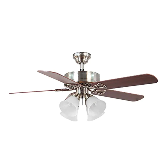
SPRINGFIELD II CEILING FAN
Purchase Date
1-800-643-0067, 8 a.m. - 6 p.m., EST, Monday - Thursday, 8 a.m. -
MODEL #E-BDB52LABZ5BC4N
Lowes.com/harborbreeze
1
ITEM #0152426
0156738
0158620
0204925
E-BDB52BNK5BC4N
E-BDB52LW5BC4N
E-BDB52MBK5BC4N
Español p. 21
LISTED
E124404
Advertisement
Chapters
Table of Contents

Related Manuals for Harbor Breeze E-BDB52LABZ5BC4N


Summary of Contents for Harbor Breeze E-BDB52LABZ5BC4N
- Page 1 ITEM #0152426 0156738 0158620 0204925 SPRINGFIELD II CEILING FAN Harbor Breeze® is a registered trademark MODEL #E-BDB52LABZ5BC4N of LF, LLC. All Rights Reserved. E-BDB52BNK5BC4N E-BDB52LW5BC4N E-BDB52MBK5BC4N Español p. 21 LISTED ATTACH YOUR RECEIPT HERE E124404 Serial Number Purchase Date Questions, problems, missing parts? Before returning to your retailer, call our customer service department at 1-800-643-0067, 8 a.m.
-
Page 2: Table Of Contents
TABLE OF CONTENTS Safety Information .......................2 Package Contents .......................4 Hardware Contents ..........................5 Preparation ..........................5 Initial Installation ........................6 Downrod-Style Fan Mounting ....................8 Closemount-Style Fan Mounting ..................10 Wiring ..........................11 Final Installation .........................13 Operating Instructions .......................16 Care and Maintenance ......................18 Troubleshooting........................18 Limited Lifetime Warranty ....................19 Replacement Parts List .....................20 SAFETY INFORMATION READ AND SAVE THESE INSTRUCTIONS... -
Page 3: Safety Information
SAFETY INFORMATION DANGER When using an existing outlet box, make sure the outlet box is securely attached to the building structure and can support the full weight of the fan. Failure to do this can result in serious injury or death. -
Page 4: Package Contents
PACKAGE CONTENTS PART DESCRIPTION QUANTITY PART DESCRIPTION QUANTITY Downrod Clip (preassembled) Switch Housing Cap Canopy (preassembled) Mounting Bracket Switch Housing Screw (preassembled) (preassembled) Motor Housing Light Kit Fitter Screw Glass Shade (preassembled) Blade Light Kit Fitter Blade Arm Socket Ring (preassembled) Pull Chain Extension Balancing Kit Motor Screw... -
Page 5: Hardware Contents
HARDWARE CONTENTS (shown actual size) Blade Fiber Screw Blade E3 Wire Washer Connector Qty. 15 + 1 extra Qty. 15 Qty. 4 + 1 extra PREPARATION Before beginning assembly of product, make sure all parts are present. Place motor on carpet or on foam to avoid damage to finish. -
Page 6: Initial Installation
INITIAL INSTALLATION Turn off circuit breakers and wall switch to the fan supply line leads. DANGER: Failure to disconnect power supply prior to installation may result in serious injury or death. Determine mounting method to use. A. Downrod mount (standard or angled ceiling) B. - Page 7 INITIAL INSTALLATION 4a. Loosen canopy mounting screws (L) in slotted holes of canopy (B) and remove the other two canopy mounting screws (L) and star washers (U). Save for later use. Remove mounting bracket (C) from canopy (B). Secure mounting bracket (C) to outlet box (not STANDARD MOUNT ANGLE MOUNT included) using screws, spring washers and flat...
-
Page 8: Downrod-Style Fan Mounting
DOWNROD-STYLE FAN MOUNTING Remove pin (M) and clip (N) from downrod (A). Partially loosen preassembled set screws and nuts in yoke at top of motor housing (D). Set Screw and Nut Yoke 2. Insert downrod (A) through canopy (B). Thread wires from motor housing (D) up through downrod (A). - Page 9 DOWNROD-STYLE FAN MOUNTING Depending on the length of downrod you use, you may need to cut the lead wires back to simplify the wiring. If you decide to cut back the lead wires, it is suggested you do so in the following manner: Ball Take the lead wires and make sure you have...
- Page 10 CLOSEMOUNT-STYLE FAN MOUNTNG Remove canopy cover from bottom of canopy (B). [NOTE: It may be necessary to use the handle end of a screwdriver (not included) to remove the canopy cover by tapping on the canopy cover from the inside of the canopy (B).] *Helpful Hint: Closemount-style mounting is more suitable for ceilings lower than 8 ft.
-
Page 11: Closemount-Style Fan Mounting
CLOSEMOUNT STYLE FAN MOUNTING Temporarily hang fan on the tab on the mounting bracket (C) using one of the non-slotted holes in the canopy (B). WIRING WARNING: To reduce the risk of fire, electrical shock, or personal injury, wire connectors provided with this fan are designed to accept only one 12-gauge house wire and two lead wires from the fan. -
Page 12: Wiring
WIRING 1b. FAN CONTROLLED BY PULL CHAIN, FAN CONTROLLED BY PULL CHAIN, LIGHT BY WALL SWITCH FAN AND LIGHT CONTROLLED BY TWO WALL SWITCHES LIGHT BY WALL SWITCH: If you intend to control the fan light with a separate wall switch, 120V POWER connect BLACK wire from fan to BLACK wire FROM CEILING... -
Page 13: Final Installation
WIRING IMPORTANT: Using a full range dimmer switch (not included) to control fan speed will cause a loud humming noise from fan. To reduce the risk of fire or electrical shock, do NOT use a full range dimmer switch to control fan speed. - Page 14 FINAL INSTALLATION Locate motor screws (I) and lock washers (K) that were previously removed (Step 5, page 7). Insert two motor screws (I) along with lock washers (K) through one blade arm (G) to attach blade arm (G) to motor housing (D). Tighten motor screws (I) securely.
- Page 15 FINAL INSTALLATION Align holes in light kit fitter (R) with holes in switch housing. Make sure to align gap on edge of light kit fitter (R) with reverse switch on switch housing for the proper fit. Then, re-insert the light kit fitter screws (Q) previously removed (Step 4, page 14) and use a Switch Phillips screwdriver (not included) to secure all light...
-
Page 16: Operating Instructions
FINAL INSTALLATION Attach applicable pull chain extensions (H) or custom pull chain extensions (not included) to the fan and light pull chains. WITHOUT LIGHT KIT WITH LIGHT KIT OPERATING INSTRUCTIONS The pull chain located on the switch housing has four positions to control fan speed. One pull is HIGH, two is MEDIUM, three is LOW and four turns Switch the fan OFF. - Page 17 OPERATING INSTRUCTIONS 3. Use the fan reverse switch, located on the switch housing, to optimize your fan for seasonal performance. A ceiling fan will allow you to raise your thermostat setting in summer Switch and lower your thermostat setting in winter Housing without feeling a difference in your comfort.
-
Page 18: Care And Maintenance
CARE AND MAINTENANCE At least twice each year, lower canopy (B) to check downrod (A) assembly, and then tighten all screws on the fan. Clean motor housing (D) with only a soft brush or lint-free cloth to avoid scratching the finish. Clean blades (F) with a lint-free cloth. You may occasionally apply a light coat of furniture polish to wood blades for added protection. -
Page 19: Limited Lifetime Warranty
TROUBLESHOOTING PROBLEM POSSIBLE CAUSE CORRECTIVE ACTION Fan operates but 1. Bulb(s) not installed correctly. 1. Re-install bulb(s). lights fail (if 2. Wires in canopy not wired properly. 2. Check wires in canopy and, if applicable). necessary, re-wire according to instructions on pages 11 and 3. -
Page 20: Replacement Parts List
0156738-G 0158620-G 0204925-G Switch Housing Cap 0152426-O 0156738-O 0158620-O 0204925-O Light Kit Fitter 0152426-R 0156738-R 0158620-R 0204925-R Socket Ring 0152426-S 0156738-S 0158620-S 0204925-S Printed in China Harbor Breeze® is a registered trademark of LF, LLC. All Rights Reserved. Lowes.com/harborbreeze KHLI1508... - Page 21 0156738 0158620 0204925 VENTILADOR DE TECHO SPRINGFIELD II Harbor Breeze ® es una marca registrada de LF, LLC. Todos los derechos reservados. MODELO #E-BDB52LABZ5BC4N E-BDB52BNK5BC4N E-BDB52LW5BC4N E-BDB52MBK5BC4N LISTED ADJUNTE SU RECIBO AQUÍ E124404 Número de serie Fecha de compra ¿Preguntas, problemas, piezas faltantes? Antes de volver a la tienda, llame a nuestro Departamento de Servicio al Cliente al 1-800-643-0067, de lunes a jueves de 8 a.m.
-
Page 22: Información De Seguridad
ÍNDICE Información de seguridad ....................22 Contenido del paquete .......................24 Aditamentos ...........................25 Preparación ............................25 Instalación inicial ........................26 Estilo de montaje de varilla del ventilador ................28 Estilo de montaje cerrado del ventilador ................30 Cableado ..........................31 Instalación final ........................33 Instrucciones de funcionamiento ..................36 Cuidado y mantenimiento ....................38 Solución de problemas .......................38 Garantía limitada de por vida .....................40... - Page 23 INFORMACIÓN DE SEGURIDAD PELIGRO Si utiliza una caja de salida existente, asegúrese de que esté bien sujeta a la estructura del edificio y que pueda sostener el peso del ventilador. El incumplimiento de dicho paso podría provocar lesiones graves o la muerte. La estabilidad de la caja de salida es fundamental para minimizar el tambaleo y el ruido en el ventilador una vez que la instalación esté...
-
Page 24: Contenido Del Paquete
CONTENIDO DEL PAQUETE PIEZA DESCRIPCIÓN CANTIDAD PIEZA DESCRIPCIÓN CANTIDAD Varilla Tapa de la carcasa del interruptor (preensamblada) Base Tornillo de la carcasa del Abrazadera de montaje interruptor (preensamblado) (preensamblada) Tornillo del soporte del kit Carcasa del motor de iluminación Pantalla de vidrio (preensamblado) Aspa Soporte del kit de iluminación... -
Page 25: Aditamentos
ADITAMENTOS (se muestran en tamaño real) Tornillo Arandela para aspa para aspa Conector de de fibra Cant. 15 cables E3 + 1 adicional Cant. 15 Cant. 4 + 1 adicional PREPARACIÓN Antes de comenzar a ensamblar el producto, asegúrese de tener todas las piezas. Compare las piezas con la lista del contenido del paquete y la lista del contenido de aditamentos. -
Page 26: Instalación Inicial
INSTALACIÓN INICIAL Interrumpa el suministro de electricidad hacia del ventilador apagando los interruptores de circuito y el interruptor de pared. PELIGRO: Si no interrumpe el suministro de electricidad antes de la instalación, pueden producirse lesiones graves o la muerte. Determine el método de montaje que utilizará. A. - Page 27 INSTALACIÓN INICIAL 4a. Afloje los tornillos de montaje de la base (L) en los orificios ranurados de la base (B) y retire los otros dos tornillos de montaje de la base (L) y las arandelas de estrella (U). Consérvelos para usarlos posteriormente.
-
Page 28: Estilo De Montaje De Varilla Del Ventilador
ESTILO DE MONTAJE DE VARILLA DEL VENTILADOR Retire el pasador (M) y el sujetador (N) de la varilla (A). Afloje parcialmente los tornillos de fijación y las tuercas preensambladas en la horquilla en la parte superior del bastidor del motor (D). Tornillo de fijación y tuerca... - Page 29 ESTILO DE MONTAJE DE VARILLA DEL VENTILADOR Dependiendo del largo de la varilla que utilice, es posible que necesite cortar los cables conductores para simplificar el cableado. Si decide cortar los cables conductores, se sugiere hacerlo de la siguiente manera: Bola Tome los cables conductores y asegúrese de jalarlos completamente a través de la parte superior de la...
-
Page 30: Estilo De Montaje Cerrado Del Ventilador
ESTILO DE MONTAJE CERRADO DEL VENTILADOR Retire la cubierta de la base desde la parte inferior de la base (B). [NOTA: Es posible que sea necesario usar el extremo del mango de un destornillador (no se incluye) para retirar la cubierta de la base golpeándola desde el interior de la base (B)]. -
Page 31: Cableado
ESTILO DE MONTAJE CERRADO DEL VENTILADOR Temporalmente cuelgue lel ventilador en la lengüeta de la abrazadera de montaje (C) usando uno de los orificios sin ranura de la base (B). Lengüeta CABLEADO ADVERTENCIA: Para reducir el riesgo de incendios, descargas eléctricas o lesiones personales, los conectores de cables proporcionados con este ventilador están diseñados para soportar solo un conductor de la casa de calibre 12 y dos cables conductores del ventilador. - Page 32 CABLEADO VENTILADOR CONTROLADO POR CADENA DE TIRO Y LUZ 1b. VENTILADOR CONTROLADO POR CADENA DE CONTROLADA POR INTERRUPTOR DE PARED TIRO Y LUZ CONTROLADA POR INTERRUPTOR DE PARED: Si desea controlar la luz del ventilador con un interruptor de pared separado, conecte el conductor ALIMENTACIÓN NEGRO del ventilador con el conductor NEGRO del DE 120 V DESDE...
-
Page 33: Instalación Final
CABLEADO IMPORTANTE: El uso de un regulador de intensidad de rango completo (no se incluye) para controlar la velocidad del ventilador hará que éste produzca un zumbido intenso. Para reducir el riesgo de incendios o descargas eléctricas, NO use un regulador de intensidad de rango completo para controlar la velocidad del ventilador. - Page 34 INSTALACIÓN FINAL Localice los tornillos del motor (I) y las arandelas de seguridad (K) que retiró anteriormente (paso 5, página 27). Inserte dos tornillos del motor (I) junto con arandelas de seguridad (K) a través de un brazo de aspa (G) para fijar el brazo de aspa (G) a la carcasa del motor (D).
- Page 35 INSTALACIÓN FINAL Alinee los orificios del soporte del kit de iluminación (R) con los orificios de la carcasa del interruptor. Asegúrese de alinear el espacio en el extremo del soporte del kit de iluminación (R) con el interruptor de reversa de la carcasa del interruptor para que calce Carcasa del Espacio correctamente.
-
Page 36: Instrucciones De Funcionamiento
INSTALACIÓN FINAL Conecte las extensiones para la cadena de tiro (H) o las extensiones para la cadena de tiro SIN EL CON EL personalizadas (no incluidas) con las cadenas de KIT DE ILUMINACIÓN KIT DE ILUMINACIÓN tiro del ventilador y luz correspondientes. INSTRUCCIONES DE FUNCIONAMIENTO La cadena de tiro ubicada en la carcasa del interruptor tiene cuatro posiciones para controlar la... - Page 37 INSTRUCCIONES DE FUNCIONAMIENTO 3. Utilice el interruptor de reversa del ventilador, ubicado en la carcasa del interruptor, para optimizar el rendimiento de su ventilador según la estación del año. Un ventilador de techo le Carcasa permitirá elevar la configuración de su interruptor termostato en verano y disminuirla en invierno, sin sentir una diferencia en su comodidad.
-
Page 38: Cuidado Y Mantenimiento
CUIDADO Y MANTENIMIENTO Al menos dos veces al año, baje la base (B) para revisar el ensamble de la varilla (A) y luego apriete todos los tornillos del ventilador. Limpie la carcasa del motor (D) sólo con un cepillo suave o un paño que no produzca pelusas para evitar rayar el acabado. - Page 39 SOLUCIÓN DE PROBLEMAS PROBLEMA CAUSA POSIBLE ACCIÓN CORRECTIVA Hay un tambaleo 6. El (los) tornillo(s) de fijación en la 6. Apriete firmemente el (los) excesivo. horquilla de la carcasa del motor tornillo(s) de fijación de no está(n) bien apretado(s). la horquilla. 7.
-
Page 40: Garantía Limitada De Por Vida
GARANTÍA LIMITADA DE POR VIDA El distribuidor garantiza que este ventilador no presentará defectos de fabricación ni en los materiales presentes en el momento del transporte desde la fábrica durante un período limitado de por vida a partir de la fecha de compra. Esta garantía es válida sólo para el comprador original. El distribuidor acepta reparar cualquier defecto sin cargo o, según nuestro criterio, reemplazar el ventilador de techo por un modelo comparable o superior. -
Page 41: Lista De Piezas De Repuesto
Tapa de la carcasa del 0152426-O 0156738-O 0158620-O 0204925-O interrupton Soporte del kit de 0152426-R 0156738-R 0158620-R 0204925-R iluminación Anillo del portalámpara 0152426-S 0156738-S 0158620-S 0204925-S Impreso en China Harbor Breeze ® es una marca registrada de LF, LLC. Todos los derechos reservados. Lowes.com/harborbreeze...
Need help?
Do you have a question about the E-BDB52LABZ5BC4N and is the answer not in the manual?
Questions and answers