Table of Contents
Advertisement
Available languages
Available languages
Harbor Breeze® is a registered trademark of
LF, LLC. All Rights Reserved.
Federal regulations require ceiling fans with light kits manufactured or imported after
January 1, 2009, to limit total wattage consumed by the light kit to 190W. Therefore,
this fan is equipped with a wattage limiting device. If you lamp this fan's light kit with
bulbs totaling more than 190W, the wattage limiting device will reduce the watts
consumed to 190W.
ATTACH YOUR RECEIPT HERE
Serial Number
Questions, problems, missing parts? Before returning to your retailer, call or contact our
customer service department at 1-800-527-1292, 8:30 a.m. - 5:00 p.m., CST, Monday - Friday.
Purchase Date
1
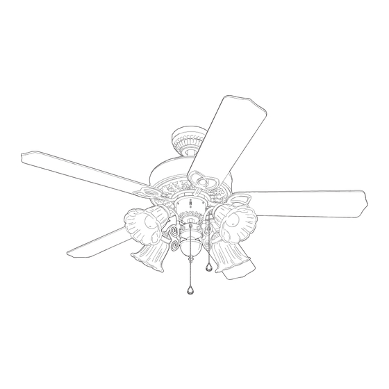
SHREVEPORT CEILING FAN
MODEL #E-NO52AB5C4
ITEM #0294986
0294985
E-NO52PAN5C4
Español p. 19
E192641
Advertisement
Chapters
Table of Contents

Subscribe to Our Youtube Channel
Related Manuals for Harbor Breeze SHREVEPORT E-NO52AB5C4


Summary of Contents for Harbor Breeze SHREVEPORT E-NO52AB5C4
- Page 1 ITEM #0294986 0294985 SHREVEPORT CEILING FAN Harbor Breeze® is a registered trademark of MODEL #E-NO52AB5C4 LF, LLC. All Rights Reserved. E-NO52PAN5C4 Español p. 19 Federal regulations require ceiling fans with light kits manufactured or imported after January 1, 2009, to limit total wattage consumed by the light kit to 190W. Therefore, this fan is equipped with a wattage limiting device.
-
Page 2: Table Of Contents
TABLE OF CONTENTS Safety Information ..…………………………………………………………………………...…….2 - 3 Package Contents ..…………………………………………………………………..……..…..…..4 Hardware Contants ........................5 Preparation ..….…………………..……………………….…………….………………..5 Initial Installation ....……………………...………………………………….....6 - 7 Downrod Style Fan Mounting ...…………………………..……………..……......7 - 8 Closemount Style Fan Mounting ……………………....…..……………………..8 - 9 Wiring ................………………………....9 - 11 Final Installation ………….…………….……………………….…………..….....11 - 14 Operation Instructions..............………………………………...14 - 15 Care and Maintenance ..……………………………………………………………….......15... -
Page 3: Safety Information
SAFETY INFORMATION WARNINGS To reduce the risk of fire, electrical shock, or personal injury, mount fan to outlet box marked "ACCEPTABLE FOR FAN SUPPORT" and use mounting screws provided with the outlet box. Most outlet boxes commonly used for the support of lighting fixtures are not acceptable for fan support and may need to be replaced. -
Page 4: Package Contents
PACKAGE CONTENTS PART DESCRIPTION QUANTITY PART DESCRIPTION QUANTITY Downrod Motor Screw (preassembled) Canopy 6 mm Lock Washer (preassembled) Mounting Bracket Canopy Mounting Screw Motor Housing (preassembled) Switch Housing Pin (preassembled) Light Kit Fitter Clip (preassembled) Blade Pull Chain Extension Blade Arm Candelabra Base Bulb Glass Shade IMPORTANT REMINDER: You must... -
Page 5: Hardware Contants
HARDWARE CONTENTS (shown actual size) Blade Fiber Lock Screw Blade Washer Thumb E3 Wire Washer Screw Connector Qty. 15 Qty. 1 Qty. 1 Qty. 15 Qty. 12 Qty. 4 PREPARATION Before beginning assembly and installation of product, make sure all parts are present. Compare parts with package contents list and hardware contents above. -
Page 6: Initial Installation
INITIAL INSTALLATION Turn off circuit breakers and wall switch to the fan supply line leads. (Fig. 1) DANGER: Failure to disconnect power supply prior to installation may result in serious injury or death. Determine mounting method to use. (Fig. 2) A. -
Page 7: Downrod Style Fan Mounting
INITIAL INSTALLATION 5. Remove motor screws (J) and 6 mm lock washers (K) from underside of motor and save for blade arm (H) attachment later on. [If there are plastic motor blocks installed with the motor screws (J) and 6 mm lock washers (K), discard the plastic motor blocks.] (Fig. -
Page 8: Closemount Style Fan Mounting
DOWNROD STYLE FAN MOUNTING Depending on the length of downrod (A) you use, you may need to cut the lead wires back to simplify the wiring. If you decide to cut back the lead wires, it is suggested that you do so in the following manner: Ball Take the lead wires and make sure that you have pulled them all the way through the top of the downrod... -
Page 9: Wiring
CLOSEMOUNT STYLE FAN MOUNTING If neccessary, remove every other screw and lock washer from top of motor housing (D). (If there are only three screws and lock washers in top of motor housing (D), the other three screws and lock Set Screw washers will be located in one of the hardware packs.) (Fig. - Page 10 WIRING Choose wiring diagram (Fig. 1A, Fig. 1B or Fig. 1C) FAN AND LIGHT CONTROLLED BY PULL CHAINS that fits your situation and make appropriate wiring connections as follows: [NOTE: For each wire BLACK connection below, use one of the wire connectors WHITE 120 V Power FROM...
-
Page 11: Final Installation
WIRING Wrap electrical tape around each individual wire connector (CC) down to the wire as shown in Fig. 2. WARNING: Make sure no bare wire or wire strands are visible after making connections. Place green and white connections on opposite side of box from the black and blue (if applicable) connections. - Page 12 FINAL INSTALLATION Partially insert three blade screws (AA), along with three fiber blade washers (BB), to attach one blade arm (H) to a blade (G). Then, tighten each blade screw (AA) starting with the one in the middle. (Fig. 2) Repeat with remaining blades (G).
- Page 13 FINAL INSTALLATION Connect WHITE wire from light kit fitter (F) to WHITE wire from switch housing (E). Connect BLACK wire from light kit fitter (F) to RED wire from switch Molex housing (E). Make sure that molex connections are Connections secure.
-
Page 14: Operation Instructions
FINAL INSTALLATION Install four candelabra base 40-watt max. bulbs (P) included. (Fig. 10) Important: When you need to replace bulbs, please allow bulb(s) and glass shades(s) (I) to cool down before touching the bulb(s) or the glass shades(s) (I). Pull chain extensions (O) supplied in one of the hardware packs or custom pull chain extensions (sold separately) may be attached to fan and light pull chains. -
Page 15: Care And Maintenance
OPERATION INSTRUCTIONS Use the fan reverse switch, located on the switch Switch housing, to optimize your fan for seasonal Housing performance. (Fig. 3) A ceiling fan will allow you to raise your thermostat setting in summer and lower your thermostat setting in winter without feeling a difference in your comfort. -
Page 16: Troubleshooting
TROUBLESHOOTING If you have any questions regarding the product please call customer service at 1-800-527-1292, 8:30 a.m. - 5 p.m., CST, Monday - Friday. Warning: Before beginning work, shut off the power supply to avoid electrical shock. PROBLEM POSSIBLE CAUSE CORRECTIVE ACTION Fan does not move. -
Page 17: Warranty
TROUBLESHOOTING PROBLEM POSSIBLE CAUSE CORRECTIVE ACTION Fan operates but light 4. Wires not connected properly. 4. Check that wires in switch fails (if applicable). housing (E) are connected properly according to instructions on page 13. Lights dim when turning 1. Fan is lamped with more than 1. -
Page 18: Replacement Parts List
REPLACEMENT PARTS LIST For replacement parts, call our customer service department at 1-800-527-1292, 8:30 a.m. - 5:00 p.m., CST, Monday - Friday. When ordering parts, please have the Model # or Item # of the fan available, which can be found on page 1. PART DESCRIPTION Downrod... - Page 19 ARTÍCULO #0294986 0294985 VENTILADOR DE TECHO SHREVEPORT Harbor Breeze ® es una marca registrada de LF, LLC. Todos los derechos reservados. MODELO #E-NO52AB5C4 E-NO52PAN5C4 Los reglamentos federales requieren que los ventiladores de techo con kit de iluminación fabricados o importados después del 1 de enero de 2009, tengan un límite de vataje total consumido por el kit de iluminación de 190 vatios.
- Page 20 ÍNDICE Información de seguridad …………………………..………………………………...……..20 - 21 Contenido del paquete ..……………………………………………………….……..……..…..…..22 Aditamentos ..........................23 Preparación ..….….….…………………..……………………….……………...……………..23 Instalación inicial .....…………………...…………………………………......24 - 25 Estilo de montaje de varilla del ventilador ……………..……...…..……......25 - 26 Estilo de montaje cerrado del ventilador ………………...…..……………………..26 - 27 Cableado ................………………………....27 - 29 Instalación final ………….…………….……………………….…………..…......29 - 32...
-
Page 21: Información De Seguridad
INFORMACIÓN DE SEGURIDAD ADVERTENCIAS Para reducir el riesgo de incendios, descargas eléctricas o lesiones personales, monte el ventilador en una caja de salida marcada como “ACCEPTABLE FOR FAN SUPPORT” (APTA PARA SOPORTE DE VENTILADOR) y utilice los tornillos de montaje que se proporcionan con la caja de salida. -
Page 22: Contenido Del Paquete
CONTENIDO DEL PAQUETE PIEZA DESCRIPCIÓN CANTIDAD PIEZA DESCRIPCIÓN CANTIDAD Varilla Tornillo del motor Base (preensamblado) Abrazadera de montaje Arandela de seguridad de 6 mm (preensamblada) Carcasa del motor Tornillo de montaje de la base Carcasa del interruptor (preensamblado) Soporte del kit de iluminación Pasador (preensamblado) Aspa Sujetador (preensamblado) -
Page 23: Aditamentos
ADITAMENTOS (se muestran en tamaño real) Tornillo para Arandela Tuerca Arandela de aspa para aspa hexagonal seguridad Tornillo de Conector de de fibra mariposa cables E3 Cant. 15 Cant. 1 Cant. 1 Cant. 15 Cant. 12 Cant. 4 PREPARACIÓN Antes de comenzar a ensamblar e instalar el producto, asegúrese de tener todas las piezas. Compare las piezas con la lista del contenido del paquete y los aditamentos mencionados anteriormente. -
Page 24: Instalación Inicial
INSTALACIÓN INICIAL Interrumpa el suministro de energía del ventilador apagando los interruptores de circuito y el interruptor de pared. (Fig. 1) PELIGRO: Si no interrumpe el suministro de electricidad antes de la instalación, pueden producirse lesiones graves o la muerte. Determine el método de instalación que utilizará. -
Page 25: Estilo De Montaje De Varilla Del Ventilador
INSTALACIÓN INICIAL 5. Retire los tornillos del motor (J) y las arandelas de seguridad de 6 mm (K) en la parte inferior del motor y guárdelos para fijar el brazo del aspa (H) más adelante. [Si hay topes plásticos del motor instalados con los tornillos del motor (J) y las arandelas de seguridad de 6 mm (K), deseche los topes plásticos del motor]. -
Page 26: Estilo De Montaje Cerrado Del Ventilador
ESTILO DE MONTAJE DE VARILLA DEL VENTILADOR Dependiendo del largo de la varilla (A) que utilice, es posible que necesite cortar los cables conductores para simplificar el cableado. Si decide cortar los cables conductores, se sugiere hacerlo de la siguiente manera: Tome los cables conductores y asegúrese de jalarlos Bola completamente a través de la parte superior de la varilla... -
Page 27: Cableado
ESTILO DE MONTAJE CERRADO DEL VENTILADOR Si es necesario, retire todos los otros tornillos y las arandelas de seguridad de la parte superior de la carcasa del motor (D). (Si sólo hay tres tornillos Tornillo de y arandelas de seguridad en la parte superior de fijación la carcasa del motor (D), los otros tres tornillos y arandelas de seguridad estarán ubicados en uno... - Page 28 CABLEADO Escoja el diagrama de cableado (Fig. 1A, Fig. 1B o Fig. VENTILADOR Y LUZ CONTROLADOS POR CADENAS DE TIRO 1C) que se ajuste a su situación y realice las conexiones del cableado adecuadas como se indica a continuación: NEGRO [NOTA: Para cada conexión de cables a continuación, BLANCO Alimentación de...
-
Page 29: Instalación Final
CABLEADO Envuelva con cinta aislante cada conector de cable (CC) individual hacia abajo del cable como se muestra en la Fig. 2. ADVERTENCIA: Asegúrese de que no haya conductores desnudos ni filamentos de conductores visibles después de hacer la conexión. Coloque las conexiones verdes y blancas en el lado opuesto de las conexiones negras y azules de la caja (si corresponde). - Page 30 INSTALACIÓN FINAL Inserte parcialmente tres tornillos para las aspas (AA), junto con tres arandelas para las aspas de fibra (BB) para fijar un brazo del aspa (H) a un aspa (G). Luego, apriete cada uno de los tornillos para las aspas (AA), comenzando por el que está en el centro.
- Page 31 INSTALACIÓN FINAL Conecte el conductor BLANCO de la carcasa del interruptor (F) al conductor BLANCO del soporte del kit de iluminación (E). Conecte el conductor NEGRO Conexiones de la carcasa del interruptor (F) al conductor ROJO molex del soporte del kit de iluminación (E). Asegúrese de que las conexiones molex sean seguras.
-
Page 32: Instrucciones De Funcionamiento
INSTALACIÓN FINAL Instale las cuatro bombillas de base candelabro de 40 vatios como máximo (P) incluidas. (Fig. 10) Importante: Cuando necesite reemplazar la bombilla, deje que ésta y la pantalla de vidrio (I) se enfríen antes de tocar la bombilla o la pantalla de vidrio (I). Las extensiones de la cadena de tiro (O) que se suministran en uno de los paquetes de aditamentos o las extensiones para cadenas de tiro a medida... -
Page 33: Cuidado Y Mantenimiento
INSTRUCCIONES DE FUNCIONAMIENTO Utilice el interruptor de reversa del ventilador, Carcasa del ubicado en la carcasa del interruptor, para optimizar interruptor el rendimiento de su ventilador según la estación del año. (Fig. 3) Un ventilador de techo le permitirá elevar la configuración de su termostato en verano y disminuirla en invierno, sin afectar su confort. -
Page 34: Solución De Problemas
SOLUCIÓN DE PROBLEMAS Si tiene preguntas relacionadas con el producto, llame al Departamento de Servicio al Cliente al 1-800-527-1292, de lunes a viernes de 8:30 a.m. a 5 p.m., hora central estándar. Advertencia: Antes de comenzar cualquier trabajo, corte el suministro de electricidad para evitar descargas eléctricas. -
Page 35: Garantía
SOLUCIÓN DE PROBLEMAS PROBLEMA CAUSA POSIBLE ACCIÓN CORRECTIVA 4. Los cables no están conectados 4. Verifique que los cables en la carcasa El ventilador funciona, correctamente. del interruptor (E) estén bien conectados pero la luz no de acuerdo con las instrucciones de la (si corresponde). -
Page 36: Lista De Piezas De Repuesto
LISTA DE PIEZAS DE REPUESTO Para obtener piezas de repuesto, llame a nuestro Departamento de Servicio al Cliente al 1-800-527-1292, de lunes a viernes, de 8:30 a.m. a 5:00 p.m., hora central estándar. Cuando pida piezas, tenga a mano el número de modelo o número de artículo del ventilador, los que aparecen en la página 19.
Need help?
Do you have a question about the SHREVEPORT E-NO52AB5C4 and is the answer not in the manual?
Questions and answers