Table of Contents
Advertisement
Quick Links
Download this manual
See also:
Troubleshooting Manual
Advertisement
Table of Contents

Related Manuals for Z Corporation ZPrinter 650


Summary of Contents for Z Corporation ZPrinter 650
-
Page 1: Hardware Manual
® ZPrinter Hardware Manual Part Number 09577 Rev. A 10/21/08 All Rights Reserved... - Page 2 Z Corporation. The information contained herein is for the use of Z Corporation customers, who are permitted to create brief excerpts for the purposes of training and review. This information may not be incorporated in any commercial pro- grams, books, databases, or in any kind of software without the consent of Z Corporation.
-
Page 3: Change History
Your ZPrinter® is guaranteed to be free of defects in materials and workmanship, when used for produc- tion of early-stage appearance models and prototypes and with Z Corporation consumables, for the period described below under WARRANTY PERIOD. All consumables and materials are guaranteed to perform as described in their specifications when stored and used as directed, up to the expiry date printed on the label. -
Page 4: Table Of Contents
1.7.3 Post-Processing Unit (PPU) Interior ..........8 1.7.4 Printer Storage.................. 9 1.7.5 Post-Processing Unit (PPU) Storage..........10 1.8 ZPrinter 650 Rear View ................11 1.9 Service Station..................12 1.10 Parking Caps ..................13 1.11 Carriage, Print Heads, and Pogo Pins............ 14 1.11.1 Front View.................. - Page 5 ZPrinter 650 Hardware Manual ® 2.8 Transform The Part in ZPrint ..............24 2.9 Fixtures ..................... 26 2.9.1 Create a Fixture for an entire part............. 27 2.9.2 Create a Fixture for a portion of a part..........28 2.10 Check the Build Layers for Errors or a Collision ........29 2.11 Check The Build Settings ...............
- Page 6 ® 6.8 Clean The Spreader Roller ............... 70 6.9 Printer Storage Preparation ..............70 7 Troubleshooting the ZPrinter 650 ..........71 7.1 Try This First..................... 72 7.2 Problems Powering Up ................73 7.3 Print Head Errors/ Weak Parts ..............74 7.3.1 Try This First..................
-
Page 7: Zprinter 650 Overview
® 1 ZPrinter 650 Overview Welcome to the exciting world of 3D Printing with our newest 3D Printer, the ZPrinter 650. The ZPrinter 650 incorporates many new features that automate and streamline the 3D printing process. The full-color capability, an easy-to-use, quiet, office-friendly design, combined with high-performance composite materi- als, makes ZPrinter 650 the fastest, most cost-effective 3D printer available today for rapid prototyping. -
Page 8: Computer/System Requirements
ZPrinter 650 Hardware Manual ZPrinter 650 Overview ® Build Volume 10” x 15” x 8” (254 mm x 381 mm x 203 mm) 1200 cubic inches build capacity Build Speed 2-4 layers per minute Layer Thickness .0035” - .004” (.089 - .102 mm) - Page 9 ZPrinter 650 Hardware Manual ZPrinter 650 Overview ® • A 3D Printer • Importing a solid 3D modeling file into the ZPrint Software • Setting up your files to print in the ZPrint/ZEdit Software • Printing, powder removal, and drying the part •...
-
Page 10: Printing Process Diagram
ZPrinter 650 Hardware Manual ZPrinter 650 Overview ® 1.5 3D Printing Process Diagram 1.6 Important Terms Air Wand - The tool located in the Post-Processing Unit that supplies air pressure. Use this tool to remove all remaining powder from a part after the initial (automatic or manual) powder removal. - Page 11 Print Head - There are five Print Heads for the ZPrinter 650 - clear, black, cyan, magenta, and yellow. All are HP11 print cartridges. When a new HP11 print head is installed, the printer runs an automatic purge cycle to clean the print head of its ink and to prepare it for dispensing binder.
-
Page 12: Zprinter 650 Components
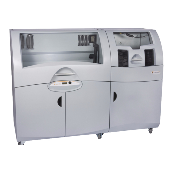
ZPrinter 650 Hardware Manual ZPrinter 650 Overview ® 1.7 ZPrinter 650 Components The main components of the ZPrinter 650 system are highlighted below. 1.7.1 System Exterior Number Component Printer Post-Processing Unit (PPU) Control Panel Printer Storage Compartment PPU Storage Compartment Arm Holes zcentral.zcorp.com... -
Page 13: Printer Interior
ZPrinter 650 Hardware Manual ZPrinter 650 Overview ® 1.7.2 Printer Interior Number Component Binder Cartridges Debris Separator Heater Vent Vacuum Hose Service Station Deck Fast Axis Assembly Build Bed Front Overflow LCD Display Control Knob zcentral.zcorp.com All Rights Reserved 10/21/08... -
Page 14: Post-Processing Unit (Ppu) Interior
ZPrinter 650 Hardware Manual ZPrinter 650 Overview ® 1.7.3 Post-Processing Unit (PPU) Interior Number Component Air Wand Air Pressure Control Nut Air Hose Heater Vent Carbon Filter Post-Processing Tray Accessory Tray zcentral.zcorp.com All Rights Reserved 10/21/08... -
Page 15: Printer Storage
ZPrinter 650 Hardware Manual ZPrinter 650 Overview ® 1.7.4 Printer Storage Number Component Tools and Acessories Storage Cleaning Solution Cartridge Print Head Storage Waste Tray zcentral.zcorp.com All Rights Reserved 10/21/08... -
Page 16: Post-Processing Unit (Ppu) Storage
ZPrinter 650 Hardware Manual ZPrinter 650 Overview ® 1.7.5 Post-Processing Unit (PPU) Storage Number Component Tool Basket Parts Trays (shown under Dipping Kit) Accessory Tray zcentral.zcorp.com All Rights Reserved 10/21/08... -
Page 17: Zprinter 650 Rear View
ZPrinter 650 Hardware Manual ZPrinter 650 Overview ® 1.8 ZPrinter 650 Rear View Number Component Power Switch Power Cord Network Cable Electronics Box (E-Box) Connections zcentral.zcorp.com All Rights Reserved 10/21/08... -
Page 18: Service Station
ZPrinter 650 Hardware Manual ZPrinter 650 Overview ® 1.9 Service Station Number Component Squeegee Spit Plate Front Overflow zcentral.zcorp.com All Rights Reserved 10/21/08... -
Page 19: Parking Caps
ZPrinter 650 Hardware Manual ZPrinter 650 Overview ® 1.10 Parking Caps Number Component Parking Caps (5 total) Parking Spittoon (under Parking Caps) zcentral.zcorp.com All Rights Reserved 10/21/08... -
Page 20: Carriage, Print Heads, And Pogo Pins
ZPrinter 650 Hardware Manual ZPrinter 650 Overview ® 1.11 Carriage, Print Heads, and Pogo Pins 1.11.1 Front View Number Component Print Head (removed) Print Head Contacts Pogo Pins (inside) Septum Print Head (installed) Carriage Cover zcentral.zcorp.com All Rights Reserved 10/21/08... -
Page 21: Top Inside View
ZPrinter 650 Hardware Manual ZPrinter 650 Overview ® 1.11.2 Top Inside View Number Component Pogo Pins (5 sets total) Septum (5 total) Note: Carriage cover shown removed. zcentral.zcorp.com All Rights Reserved 10/21/08... -
Page 22: Lcd Menu And Control Knob (Control Panel)
ZPrinter 650 Hardware Manual ZPrinter 650 Overview ® 1.12 LCD Menu And Control Knob (Control Panel) 1.12.1 Control Knob Operations Push the Control Knob once to: • Bring up the LCD menu. • Select a menu item. • Open a submenu. -
Page 23: Accessories Kit
ZPrinter 650 Hardware Manual ZPrinter 650 Overview ® 1.14 Accessories Kit Top Level: • Screwdriver • Debris Separator • Network (Ethernet) Cable (blue) • Direct Connection Cable (red) Not Pictured: • 3/16” Hex Key • ZPrint/ZEdit CD Middle Level: •... - Page 24 ZPrinter 650 Hardware Manual ZPrinter 650 Overview ® Both programs include a searchable Help system and links to additional information on our User Web site regarding 3D applications and printing/post-processing techniques. Post-Processing Learn more about the different post-processing products that are available to use with your printer, on the Materials section of our User Web site at zcentral.zcorp.com.
-
Page 25: Setup And Print The Build
This section will show you how to use ZPrint to get your part ready to build, including adding fixtures and transforming the part. Then it will show you how to get your ZPrinter 650 ready and actually print your part. -
Page 26: Parts Containing An Opening Or Hollow Area
ZPrinter 650 Hardware Manual Setup And Print The Build ® 2.2.1 Parts Containing an Opening or Hollow Area Place the hollow side of a part facing down in the Build Bed to allow powder to evacuate during powder removal. Depending on how the part is imported into ZPrint, you may need to use the Rotate feature to correctly orient the part. -
Page 27: Zprint/Zedit Installation
ZPrint™ Software Manual. Be sure to install the software on the same computer that is connected to your 3D Printer. Also be sure you use the version of ZPrint that came with the ZPrinter 650. If you encounter any problems during installation, please contact your local Service Provider or Reseller, or visit the Support section of our Web site at zcentral.zcorp.com. -
Page 28: Zprint Main Window
ZPrinter 650 Hardware Manual Setup And Print The Build ® 3. If the Choose Units dialog opens, choose the display units that correspond to the part dimensions and then click Next. The file is opened in a new ZPrint window using the units specified in this dialog. 4. - Page 29 ZPrinter 650 Hardware Manual Setup And Print The Build ® 3. In the Select 3D Printer dialog, choose Network as the Port Type. Click the Find button to locate the printer on the network. If the printer is connected to the network, it will appear on the list. Select the printer and click OK.
-
Page 30: Check The Default Powder Settings
ZPrinter 650 Hardware Manual Setup And Print The Build ® 2.7 Check The Default Powder Settings 1. Select Settings > Powder Settings to display the Powder Settings dialog. 2. Select the printer and the powder type from the left-side panel to view the settings for that combination. •... - Page 31 ZPrinter 650 Hardware Manual Setup And Print The Build ® ZPrint Transform Menu Positions the selected part by the amount specified for the X, Y, and Z coordinates. The default values of 0,0,0, represent the lower-left corner of the Build Translate Bed.
-
Page 32: Fixtures
ZPrinter 650 Hardware Manual Setup And Print The Build ® Mirror/Mirror Group - Mirror a part in the X, Y, or Z direction. Mirror Select your part. Select Transform > Mirror. Choose a direction to mirror the part. Justify/Justify Group - Aligns or “justifies” the selected part to a specified location in the Build Bed. -
Page 33: Create A Fixture For An Entire Part
ZPrinter 650 Hardware Manual Setup And Print The Build ® You can generate a Fixture for an entire part, for a portion of a part, or for a part feature that needs addi- tional support. Fixtures also provide these benefits: •... -
Page 34: Create A Fixture For A Portion Of A Part
ZPrinter 650 Hardware Manual Setup And Print The Build ® 4. Click OK. The Fixture is generated. The fixture is shown in white on the screen. 5. Select View > Collision Detection to ensure the Fixture is not touching the part. If the Fixture is touch- ing the part, do the following: •... -
Page 35: Check The Build Layers For Errors Or A Collision
ZPrinter 650 Hardware Manual Setup And Print The Build ® 4. When you have positioned the box, click OK in the Make Fixture dialog. The Fixture is generated for the specified area. The fixture is shown in white on the screen. 2.10 Check the Build Layers for Errors or a Collision It is strongly recommended that the Slice View (2D icon) and Collision Detection be utilized before beginning a build. -
Page 36: Prepare The Build Area
Select Printer button to locate an Online printer via a Network connection. 3. Bleed Compensation is checked (On) by default. For most ZPrinter 650 users, the Bleed Compensa- tion setting should not be unchecked (Off) except in a couple of special situations: •... -
Page 37: Print The Build
ZPrinter 650 Hardware Manual Setup And Print The Build ® A clean, properly prepared Build Bed 2.13 Print the Build 1. Select File > 3D Print, or click on the Toolbar, to display the Printer Status dialog. NOTE: ZPrint checks the printer readiness and calculates the materials needed to complete the build. - Page 38 ZPrinter 650 Hardware Manual Setup And Print The Build ® • Print in Monochrome - Prints a color part in monochrome (no color). Printing in monochrome speeds up the print time and is useful for prototypes that do not require color for evaluation. •...
-
Page 39: Dry The Part
ZPrinter 650 Hardware Manual Setup And Print The Build ® 2.14 Dry The Part When your part is finished printing, the printer runs a drying cycle. A timer on the LCD menu will count- down the time remaining to dry the part. Drying the part gives it added strength, so you should not handle parts before they have adequately dried. -
Page 40: Fine Powder Removal
ZPrinter 650 Hardware Manual Setup And Print The Build ® NOTE: Unused powder that is emptied or vacuumed from the Build Bed is recycled back into the printer Feeder so it can be used for future builds. 2.16 Fine Powder Removal After the bulk of the powder is removed from the Build Bed, gently pick up the part and place it in the Post- Processing Unit where you clean the part of any remaining powder with the Air Wand. -
Page 41: The Next Step
ZPrinter 650 Hardware Manual Setup And Print The Build ® 2.17 The Next Step Right now - after depowdering and before post-processing - while the part continues to dry, take a few min- utes and clean the printer. Regular cleaning and maintenance is the simplest, best way to ensure your parts look their best, and to keep your printer running trouble-free. -
Page 42: Routine Cleaning
ZPrinter 650 Hardware Manual Routine Cleaning ® 3 Routine Cleaning This chapter describes the routine cleaning you should complete after every build. This will prepare the printer for the next build and keep the printer running smoothly and problem free. These tasks take only a few minutes to perform but make a huge difference in how well your printer runs. -
Page 43: Empty The Debris Separator
ZPrinter 650 Hardware Manual Routine Cleaning ® 3.2 Empty The Debris Separator After vacuuming, empty the Debris Separator. The Debris Separator catches any large particles and keeps those pieces from being recycled into the feeder. To empty the Debris Separator follow the steps below. 1. -
Page 44: Clean The Parking Caps
ZPrinter 650 Hardware Manual Routine Cleaning ® 3.3 Clean The Parking Caps The Parking Caps keep the print heads from drying out between print jobs. Cleaning the Parking Caps after every build results in longer lasting print heads and precise accuracy during printing. The Parking Caps are located on the right end of the Fast Axis. - Page 45 ZPrinter 650 Hardware Manual Routine Cleaning ® 4. Squirt the distilled water onto the Caps. The water should drain out through the Spittoon under the Caps. 5. Use a dry paper towel to wipe the caps clean. 6. Remove the paper towels from the Build Bed and Deck. Wipe up any water on the Build Bed, Fast Axis or Deck.
- Page 46 ZPrinter 650 Hardware Manual Routine Cleaning ® zcentral.zcorp.com All Rights Reserved 10/21/08...
-
Page 47: Clean The Fast Axis Rails And Carriage
ZPrinter 650 Hardware Manual Routine Cleaning ® 3.4 Clean The Fast Axis Rails and Carriage Keeping the Fast Axis Rails and Carriage clean will keep the Carriage moving smoothly and thus optimize printing accuracy. 1. Pull the Fast Axis toward you. 2. -
Page 48: Clean The Service Station
ZPrinter 650 Hardware Manual Routine Cleaning ® 3.5 Clean The Service Station The function of the Service Station is to clean the print heads during printing. Clean the Service Station after every build to remove residue buildup and to ensure the printer runs optimally for your next print job. Before you begin: •... -
Page 49: Example - Clean Service Station
ZPrinter 650 Hardware Manual Routine Cleaning ® 3.5.2 Example - Clean Service Station Number Description Wash Holes Clean and Open Squeegee Clean and Dry Spit Plate Clean Housing Clean Overflow and Build Bed Clean 3.5.3 Cleaning Procedure 1. Place paper towels around the Service Station, and between the Service Station and the Build Bed. 2. - Page 50 ZPrinter 650 Hardware Manual Routine Cleaning ® 3. Position the squirt bottle close to the station and squirt water on and around the squeegee. 4. Use the cotton swabs or a paper towel and wipe the front and back of the squeegee. Use the Pick to scrape excess powder out of any corners.
- Page 51 ZPrinter 650 Hardware Manual Routine Cleaning ® 6. Wipe off any water or cleaning solution on the Wash Holes. Thoroughly wipe the Service Station clean. 7. Install a needle onto the small syringe. Gently push the tip of the needle through each of the six Wash Holes to clear them.
-
Page 52: Post-Processing With Z-Bond
Place a piece of cardboard down in your work area and place a piece of wax paper over the card- board for the part to dry on. Z Corporation also offers a Z-Bond 101 Dipping Kit, which contains all the supplies needed for post-pro- cessing. The Kit provides a convenient and cost-effective way to get everything you need. -
Page 53: Using The Post-Processing Unit
ZPrinter 650 Hardware Manual Post-Processing With Z-Bond ® 4.2 Using the Post-Processing Unit The Post-Processing Unit provides a convenient way to infiltrate parts without having to move the part to a separate work area. Follow the steps below to set up the Post-Processing Unit for infiltration. CAUTION The Post-Processing Unit is for use with Z-Bond only. -
Page 54: Post-Processing Using The Dipping Method
ZPrinter 650 Hardware Manual Post-Processing With Z-Bond ® 5. Lower the metal tray to the bottom of the Post-Processing Unit and press down to snap it in place. 6. Turn on the carbon air filter to capture any fumes from the infiltration. On the LCD Menu, select POST PROCESS MENU , then... - Page 55 ZPrinter 650 Hardware Manual Post-Processing With Z-Bond ® 1. Place wax paper where you will be working. 2. Open the bottle and attach the spout. 3. Drizzle Z-Bond onto the part. Start with the most delicate areas first. Wet as much of the part as you can easily reach.
-
Page 56: Additional Operations
5.1 The Printer Status Dialog The Printer Status dialog keeps you appraised of everything your ZPrinter 650 needs to start your print job. The two examples below show what appears when the printer is ready to print, and when it’s not ready. -
Page 57: Not Ready To Print
ZPrinter 650 Hardware Manual Additional Operations ® In the example above, the Printer Status dialog shows the printer is ready for printing. Notice that each item shows OK, and the Print button is enabled. From here you would choose your printing options and click Print to start the job. -
Page 58: Change Print Head(S)
ZPrinter 650 Hardware Manual Additional Operations ® 5.2 Change Print Head(s) If the Printer Status dialog indicates one or more print heads needs changing, follow the steps below. 1. On the Control Panel select BUILD CHAMBER , then LOWER PLATFORM . - Page 59 ZPrinter 650 Hardware Manual Additional Operations ® 6. Lift the print heads to be replaced out of their slots and properly recycle or dispose of any empty car- tridge(s). 7. Get an alcohol swab (included with your Startup Kit). Snap it to break the glass inside, and squeeze the tube to saturate the swab 8.
- Page 60 ZPrinter 650 Hardware Manual Additional Operations ® 9. Remove the new printhead from its packaging. Be sure to pull the tape tab off of the new printhead. 10. Insert each new printhead. Press down firmly on the top of the printhead, at the same side as the pogo pins, to securely fit a printhead into its slot.
-
Page 61: Add Binder
ZPrinter 650 Hardware Manual Additional Operations ® 5.3 Add Binder If there is not enough binder in one or more of the cartridges, ZPrint displays BINDER LOW in the Printer Status dialog. Important: Do not add binder unless you are prompted to in the ZPrint Printer Status dialog. To add binder, follow the steps below. -
Page 62: Add Powder To The Feeder
ZPrinter 650 Hardware Manual Additional Operations ® 5.4 Add Powder To The Feeder ZPrint evaluates the geometry of the part to determine if there is enough powder in the Feeder to complete the build. If there is not enough powder, ZPrint displays ADD POWDER in the Printer Status dialog. -
Page 63: Add Cleaning Solution
ZPrinter 650 Hardware Manual Additional Operations ® 5.5 Add Cleaning Solution If there is not enough cleaning solution, ZPrint displays ADD CLEANING SOLUTION in the Printer Status dialog. Important: Do not add cleaning solution unless you are prompted to in the ZPrint Printer Status dialog. -
Page 64: Position Build Piston (Build Bed)
ZPrinter 650 Hardware Manual Additional Operations ® 5.7 Position Build Piston (Build Bed) The Build Bed platform must be in its proper position at the top of the Build Bed in order for the printer to fill the bed and spread a layer of powder before starting a print job. If you see the message RAISE BUILD the Printer Status dialog, go to the printer and select PREP BUILD CHAMBER... -
Page 65: Printer Maintenance
ZPrinter 650 Hardware Manual Printer Maintenance ® 6 Printer Maintenance This chapter details how to perform maintenance on your printer and how to prepare your printer for stor- age if you will not be running it for extended periods. Most of these procedures are only performed when you are prompted to in the ZPrint Maintenance dialog. -
Page 66: Piston Screw Lubrication
ZPrinter 650 Hardware Manual Printer Maintenance ® 4. Using a paper towel dampened with distilled water, wipe the top and bottom Rails to remove any pow- der. Move the Carriage back and forth as needed to clean the entire length of both rails. 5. - Page 67 ZPrinter 650 Hardware Manual Printer Maintenance ® 5. Look into the left end of the printer, in between the Waste Tray and the pocket for the Cleaning Solution Cartridge and locate the piston screw. Number Component Waste Tray Piston Screw Pocket for Cleaning Solution Cartridge 6.
-
Page 68: Slow Axis Bearing Lubrication
ZPrinter 650 Hardware Manual Printer Maintenance ® 7. Touch the grease gun to the Piston Screw and squeeze the trigger twice at the top of the Piston Screw (under the Build Bed), and then squeeze the trigger once at the middle of the Piston Screw. 8. -
Page 69: Replace The Carbon Filter
ZPrinter 650 Hardware Manual Printer Maintenance ® 3. Pull the Fast Axis forward until you see the Slow Axis bearing in the center of the opening on the Fast Axis. 4. Assemble the grease gun that is part of your Accessories Kit according to the instructions. 5. -
Page 70: Clean The Alignment Sensor Window
ZPrinter 650 Hardware Manual Printer Maintenance ® Lower the retainer. 4. Remove the old Carbon Filter 5. Install the new Carbon Filter with the label at the top and facing out at you as shown. 6. Raise the retainer and latch it closed. 6.5 Clean The Alignment Sensor Window Frequency: Clean the Alignment Sensor Window every time you change a print head, or remove a print head to clean the contacts and pogo pins. -
Page 71: Clean The Fast Axis Pulleys
ZPrinter 650 Hardware Manual Printer Maintenance ® 6.6 Clean The Fast Axis Pulleys Frequency: On a regular schedule, depending on your usage. Or, whenever the printer has problems or errors related to the Fast Axis motion. 1. Slide the fast axis out toward you. 2. - Page 72 ZPrinter 650 Hardware Manual Printer Maintenance ® 2. Unsnap the top deck from the chassis by pulling up at the front edge. 3. Lift up the front edge of the deck and slide the deck out toward you. Remove the deck from the printer. zcentral.zcorp.com All Rights Reserved 10/21/08...
- Page 73 ZPrinter 650 Hardware Manual Printer Maintenance ® 4. On the LCD select VACUUM to turn the vacuum on. Thoroughly vacuum the area around the slow axis rails. Number Component Slow Axis Rails Ends of Rail 5. Using a paper towel dampened with distilled water clean the slow axis rails on both sides. Carefully clean any debris from the ends of the left rail (see also next step).
- Page 74 ZPrinter 650 Hardware Manual Printer Maintenance ® 6. Using the pick from the Accessories Kit, reach below the slow axis rail and carefully remove any debris or powder from the teeth of the pulley. Slide the fast axis assembly forward and back to rotate the pul- ley and expose all the teeth.
- Page 75 ZPrinter 650 Hardware Manual Printer Maintenance ® 9. Slide the deck back into position. Line up the cutout in the deck with the Service Station. 10. Press down on the front, middle and rear of the deck as shown to snap all 6 retainers back into posi- tion.
-
Page 76: Clean The Spreader Roller
7. Make sure the roller is completely dry before attempting to spread any powder. 6.9 Printer Storage Preparation The ZPrinter 650 should never be turned off so it can automatically service the print heads and exercise the moving components during idle times. -
Page 77: Troubleshooting The Zprinter 650
7 Troubleshooting the ZPrinter 650 If you should encounter any problems with your ZPrinter 650, the steps below will help you troubleshoot the problem and, in most cases, correct it yourself. If you need to call service, we’ve provided a list of the information to have ready for your Service Provider. -
Page 78: Try This First
ZPrinter 650 Hardware Manual Troubleshooting the ZPrinter 650 ® 7.1 Try This First Before calling for service, follow these steps: 1. Clean the machine thoroughly! This includes all parts of the deck, service station, axis rails, pulley teeth, and pogo pins. Remove any debris build up at the ends of travel, on the axis rail and even on the axis rail supports. -
Page 79: Problems Powering Up
ZPrinter 650 Hardware Manual Troubleshooting the ZPrinter 650 ® 7.2 Problems Powering Up If your printer does not power up normally, use the flowchart below. zcentral.zcorp.com All Rights Reserved 10/21/08... -
Page 80: Print Head Errors/ Weak Parts
ZPrinter 650 Hardware Manual Troubleshooting the ZPrinter 650 ® 7.3 Print Head Errors/ Weak Parts There are a number of Error Codes the printer may report that all relate to the print heads, and that all share a common set of solutions. The same solutions also apply to parts that are weak and break too eas- ily. - Page 81 ZPrinter 650 Hardware Manual Troubleshooting the ZPrinter 650 ® zcentral.zcorp.com All Rights Reserved 10/21/08...
-
Page 82: Alignment Errors
ZPrinter 650 Hardware Manual Troubleshooting the ZPrinter 650 ® 7.4 Alignment Errors If you have run an alignment pattern and the printer reports that the alignment has failed, follow the trou- bleshooting flowchart below. How to do it If it passes alignment but the print quality is not OK, see Section 7.3, ’Print Head Errors/ Weak... -
Page 83: Motion Errors - Fast Axis
ZPrinter 650 Hardware Manual Troubleshooting the ZPrinter 650 ® 7.5 Motion Errors - Fast Axis There are a number of Error Codes the printer may report that all relate to the Fast Axis, and that all share a common set of solutions. - Page 84 ZPrinter 650 Hardware Manual Troubleshooting the ZPrinter 650 ® zcentral.zcorp.com All Rights Reserved 10/21/08...
-
Page 85: Motion Errors - Slow Axis
ZPrinter 650 Hardware Manual Troubleshooting the ZPrinter 650 ® 7.6 Motion Errors - Slow Axis There are a number of Error Codes the printer may report that all relate to the Slow Axis, and that all share a common set of solutions. - Page 86 ZPrinter 650 Hardware Manual Troubleshooting the ZPrinter 650 ® zcentral.zcorp.com All Rights Reserved 10/21/08...
-
Page 87: Network Errors - Cannot Connect To Printer
ZPrinter 650 Hardware Manual Troubleshooting the ZPrinter 650 ® 7.7 Network Errors - Cannot Connect to Printer If you have trouble connecting to your printer over the network, follow the troubleshooting flowchart below. zcentral.zcorp.com All Rights Reserved 10/21/08... -
Page 88: Network Errors - Packet Timeout
ZPrinter 650 Hardware Manual Troubleshooting the ZPrinter 650 ® 7.8 Network Errors - Packet Timeout Explanation: The Packet Time Out error is a result of lost or impaired communication between the printer and the PC. A Packet Time Out error may also occur if the file is too large and the PC cannot transfer the file data fast enough. - Page 89 ZPrinter 650 Hardware Manual Troubleshooting the ZPrinter 650 ® Solution: If your parts are thin-walled or just small, you may want to consider not using the automatic Empty Build Chamber feature. We also recommend that you generate a fixture with bumpers to support your part during the automatic empty build chamber cycle.
-
Page 90: Part Quality Issues - Streaky Or Striped Parts, Delamination
ZPrinter 650 Hardware Manual Troubleshooting the ZPrinter 650 ® 7.10 Part Quality Issues - Streaky or Striped Parts, Delamination Explanation: Streaky or striped parts are caused either by powder buildup on the print head, a failed print head, or an electrical issue within the printer. Delamination (layers splitting apart) may be due to a print head that is caked with powder, or a pause in network communications. -
Page 91: Part Quality Issues - Bad Surface Finish
ZPrinter 650 Hardware Manual Troubleshooting the ZPrinter 650 ® 7.11 Part Quality Issues - Bad Surface Finish The problems behind bad surface finish on parts will be different depending on whether the rough surface is in the vertical plane or the horizontal plane. -
Page 92: Miscellaneous Problems
ZPrinter 650 Hardware Manual Troubleshooting the ZPrinter 650 ® Solution - Print Heads Troubleshoot using Section 7.3, ’Print Head Errors/ Weak Parts’. Solution - Motion Problems • Clean the Fast Axis Rails. See Section 3.4, ’Clean The Fast Axis Rails and Carriage’. -
Page 93: Binder Cartridge Is Full But Zprint Indicates Empty
ZPrinter 650 Hardware Manual Troubleshooting the ZPrinter 650 ® 7.12.2 Binder Cartridge is Full But ZPrint Indicates Empty Explanation: This is usually caused by a damaged binder cartridge, or a failure in the binder cartridge pocket. Solution: • Remove and reseat the binder cartridge. Check the following: •... -
Page 94: Error Codes And Messages - Background Details
5 print heads every time a print head is replaced. The ZPrinter 650 will prompt you when a print head has reached its maximum life and requires changing. Change the print head according to the instructions in this manual. -
Page 95: Additional Information
ZPrinter 650 Hardware Manual Troubleshooting the ZPrinter 650 ® ERROR CODE Error 2303 (0) Explanation: If the error shows 2303 (0) it means that there is excessive friction on the slow axis rails, or something is obstruct- ing the travel path of the axis. If the error is 2303 (1), it means that... - Page 96 ZPrinter 650 Hardware Manual Troubleshooting the ZPrinter 650 ® • Log File (obtainable through the ZPrint Software Service Menu) • .INI File (Obtainable through the ZPrint Software Service Menu) • SPREAD.CSV File(Z450 and Z650) (Obtainable through the ZPrint Software Service Menu, Receive File option) •...
- Page 97 ZPrinter 650 Hardware Manual ® Index Numerics 3D Print Setup dialog, 29 Debris Filter, Definition, 4 3D Printing description, 1 Debris Filter, Empty, 37 3D Printing Process Diagram, 4 Deck, Definition, 4 Default Powder Settings, 24 Default Printer Settings, 22 Default Settings, Check or Change, 22 Accuracy, Part, 19 Depowder, Definition, 4...
- Page 98 ZPrinter 650 Hardware Manual ® Index Error 43000, 77 , 79 Make Fixture, General Preferences, 27 Error 60700, 74 Materials, 2 , 89 Error 60701, 74 Mirror, Toolbar Shortcut, 26 Error 60702, 74 Monochrome, Print option, 32 Fast Axis Bearing, Lubrication, 59 Network Connectivity, 1 Feeder, Add Powder, 56 New Features, 1...
- Page 99 ZPrint, Maintenance Dialog, 59 Resolution - Printer, 2 ZPrint, Transform Part, 24 Rotate, Toolbar Shortcut, 25 ZPrint/ZEdit Installation, 21 Routine Cleaning, 36 ZPrinter 650 Overview, 1 ZPrinter 650, Components, 6 Scale, Toolbar Shortcut, 25 Select Printer, 30 Service, 89 Service Station Diagram, 12...
Need help?
Do you have a question about the ZPrinter 650 and is the answer not in the manual?
Questions and answers