Table of Contents
Advertisement
Quick Links
Advertisement
Table of Contents

Related Manuals for Digitus DN-15017


Summary of Contents for Digitus DN-15017
- Page 1 200 Mbps High-speed Powerline Router User’s Manual (DN-15017)
-
Page 2: Table Of Contents
Index FCC Part 68 ................................3 FCC Part 15 ................................4 Chapter 1 Introduction ..............................5 1.1 Overview ............................5 1.2 Features ............................5 1.3 System Requirements ........................6 Chapter 2 Installation ..............................7 2.1 Checklist ............................7 2.2 The Front LEDs ..........................8 2.3 The Rear Ports ..........................8 2.4 The Bottom Port ..........................9 Chapter 3 Configuration............................9 3.1 Determine your connection settings ....................9... - Page 3 3.6.1 Logout ............................35 3.6.2 Reboot ............................36 3.7.1 TCP/IP Settings for Windows Operating System ................ 37 Chapter 4. Powerline Networking Utility ........................ 44 4.1 Configuration Utility Setup ......................44 4.1.1 Installation of the Utility ....................... 44 4.2 Windows Configuration Utility ......................46 4.3 User Interface ..........................
-
Page 4: Fcc Part 68
FCC Part 68 This equipment complies with Part 68 of the FCC Rules. On the bottom of this equipment is a label that contains the FCC Registration Number and Ringer Equivalence Number (REN) for this equipment. You must provide this information to the telephone company upon request. -
Page 5: Fcc Part 15
FCC Part 15 The modem generates and uses radio frequency energy. If it is not installed and used properly in strict accordance with the user's manual, it may cause interference with radio and television reception. The modem has been tested and found to comply with the limits for Class B computing devices in accordance with the specifications in Subpart B, Part 15 of the FCC regulations. -
Page 6: Chapter 1 Introduction
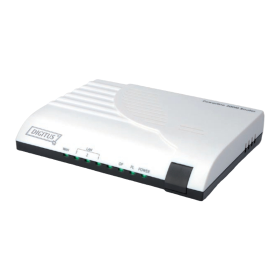
Chapter 1 Introduction Congratulations on your purchase of an Instant Powerline 200M Router with 3-port Fast Ethernet Switch and Homeplug for cable and DSL application. The Powerline Router is the perfect option to connect a small group of PCs to a high-speed Broadband Internet connection or to an Ethernet backbone. Configurable as a DHCP server, the Broadband Router acts as the only externally recognized Internet device on your local area network (LAN). -
Page 7: System Requirements
Ethernet Interface ‧Compliant with IEEE 802.3 and 802.3u 10/100 Mbps HTTP Web-Based Management ‧Firmware upgrade by UI ‧WAN and LAN side connection statistics ‧Advanced QoS ‧Password protected access ‧System log 1.3 System Requirements 1) Personal computer (PC) 2) Pentium II 233 MHz processor minimum 3) 32 MB RAM minimum 4) 20 MB of free disk space minimum 5) Ethernet Network Interface Controller (NIC) RJ45 Port... -
Page 8: Chapter 2 Installation
Chapter 2 Installation This chapter offers information about installing your router. If you are not familiar with the hardware or software parameters presented here, please consult your service provider for the values needed. 2.1 Checklist Check the shipping box carefully to ensure that the contents include the items you ordered. If any of the items are missing or damaged, contact your local distributor. -
Page 9: The Front Leds
2.2 The Front LEDs State Description POWER Press the button to power one the router. "Showtime"-successful connection between ADSL modem and telephone company's network. "Handshaking"-modem is trying to establish a connection to telco's network Modem is Flashing powered OFF ADSL Carrier Detect if LED is flash. No link. -
Page 10: The Bottom Port
2.4 The Bottom Port Connector Description Reset Switch Press 10 sec to reboot the router and restore default settings. Chapter 3 Configuration 3.1 Determine your connection settings Before you configure the router; you need to know the connection information supplied by your service provider. 3.2 Connecting the Wireless 11n Router to your network Unlike a simple hub or switch, the setup of the Powerline Router consists of more than simply plugging everything together. - Page 11 At the Password prompt, the User name is 'admin' and the password is ’admin’. You can change these later if you wish. Click 'Login' to login.
-
Page 12: Wan Setting
3.3.1 WAN Setting WAN Settings are settings that are used to connect to your ISP (Internet Service Provider). The WAN settings are provided to you by your ISP and often times referred to as "public settings". Please select the appropriate option for your specific ISP. - Page 13 Example: 168.95.1.2 IP Address: Check with your ISP provider. Subnet Mask: Check with your ISP provider. Default Gateway: Check with your ISP provider. DHCP Dynamic Host Configuration Protocol (DHCP), Dynamic IP (Get WAN IP Address automatically). If you are connected to the Internet through a Cable modem line, then a dynamic IP will be assigned. Note: WAN port gets the IP Address, Subnet Mask and default gateway IP address automatically, if DHCP client is successful.
-
Page 14: Lan Setting
3.3.2 LAN Setting These are the IP settings of the LAN (Local Area Network) interface for the device. These settings may be referred to as "private settings". You may change the LAN IP address if needed. The LAN IP address is private to your internal network and cannot be seen on the Internet. -
Page 15: Dhcp Setting
3.3.3 DHCP Setting When you enable the DHCP server, Assigned DHCP IP Address: Enter the starting IP address for the DHCP server’s IP assignment and the ending IP address for the DHCP server’s IP assignment. DHCP IP Lease Time: Assign the length of time for the IP lease, default setting is 86400 seconds. -
Page 16: Static Route Setting
3.3.4 Static Route Setting Static routes are special routes that the network administrator manually enters into the router configuration. You could build an entire network based on static routes. The problem with doing this is that when a network failure occurs, the static route will not change without you performing the change. -
Page 17: Nat Setting
3.3.5 NAT Setting Network Address Translation: Enable/Disable NAT. IPSec Pass Through: IPsec (Internet Protocol Security) is a framework for a set of protocols for security at the network or packet processing layer of network communication. Enable/Disable this framework verification. PPTP Pass Through: PPTP (Point-to-Point Tunneling Protocol) is a protocol that allows corporations to extend their own corporate network through private "tunnels"... - Page 18 put anything valuable inside the house where it can be properly secured. Virtual Server Mapping A Virtual Server is defined as a service port, and all requests to this port will be redirected to the computer specified by the server IP. Enable: Enable/Disable the virtual server mapping, default setting is Disable.
-
Page 19: Packet Filter Setting
3.3.6 Packet Filter Setting WAN – Packet Filter Use IP Filters to deny particular WAN IP addresses from the Internet. You can deny special port number or all ports for a specific IP address. You will only need to input the WAN IP address(es) of the computer(s) that will be denied. - Page 20 Enable: Enable/Disable the LAN packet filter, default setting is Disable. Source IP: The IP address of the LAN computer that will be denied access to the Internet. You can also add a range of IP addresses. Destination Port: The single port or port range that will be denied access to the Internet. If no port is specified, all ports will be denied access.
-
Page 21: Url Filter Setting
3.3.7 URL Filter Setting With security reason, the URL Filter provides the enterprise to manage and restrict employee access to non-business or undesirable content on the Internet. URL Filter is a web solution that blocks web-sites access according the URL Filter String no matter the URL string is found full or partial matched with a keyword. For example, if you add URL Filter String with keyword “sex”, the ATA device will limit local hosts to access the web site or web pages such as “www.sex.com”... -
Page 22: Security Setting
3.3.8 Security Setting Intrusion Detection: Enable/Disable the intrusion detection. -
Page 23: Upnp Setting
3.3.9 UPNP Setting UPnP (Universal Plug-and-Play). Network architecture based on TCP/IP and intended to allow terminals to be networked without the need for configuration. In the Barricade router, for example, the correct ports are automatically opened for applications like Net meeting, online games, etc. You can choose to enable or disable the UPnP Service. -
Page 24: Ddns Setting
3.3.10 DDNS Setting DDNS is a method of keeping a domain name linked to a changing (dynamic) IP address. With most Cable and DSL connections, you are assigned a dynamic IP address and that address is used only for the duration of that specific connection. -
Page 25: Qos Setting
3.3.11 QOS Setting The QOS (Quality Of Service) is to guarantee that the Voice and Data should be transmitting at the same time and Data couldn’t influence the Voice quality. When TOS bits is enabled, it will guarantee the Voice have the first priority pass through the TOS enable devices. -
Page 26: System Information
3.4.1 System Information This page displays the current information for the device. It will display the LAN, WAN, and system firmware information. This page will display different information for you, according your WAN setting (Static IP, DHCP, or PPPoE). If your WAN connection is set up for Dynamic IP address, there will be a Release button and Renew button. Use Release to disconnect from your ISP and use Renew to connect to your ISP. -
Page 27: Routing Table
3.4.2 Routing Table A routing table contains the information necessary to forward a packet along the best path toward its destination. Each packet contains information about its origin and destination. When a packet is received, a network device examines the packet and matches it to the routing table entry providing the best match for its destination. The table then provides the device with instructions for sending the packet to the next hop on its route across the network. -
Page 28: Packet Statistics
3.4.3 Packet Statistics The device keeps statistic of the data traffic that it handles. You are able to view the amount of Receive and Sent packets that passes through the device on both the WAN port and the LAN ports. The traffic counter will reset when the device is rebooted. -
Page 29: System Log
3.4.4 System Log The log file keeps a running log of events and activities occurring on the device. The log always displays recent logs. When the device is rebooted, the logs would not be cleared. -
Page 30: Admin Account
3.5.1 Admin Account The administrator account can access the management interface through the web browser. Only the administrator account has the ability to change account password. Administrator Name: Assign a name to represent the administrator account. Maximum 16 characters. Legal characters can be the upper letter “A”... -
Page 31: System Log Setting
3.5.2 System Log Setting The log file keeps a running log of events and activities occurring on the device. The log always displays recent logs. When the device is rebooted, the logs would not be cleared. -
Page 32: Data / Time
3.5.3 Data / Time Date Time Set By: Manual Time Setting or NTP Time Server. Manual Time Setting: If you choose this item, then go to the fields of Date Value Setting and Time Value Setting for setting time. NTP Time Server: If you choose this item, then go to the filed of NTP Server Address to assign the domain name for NTP Server. -
Page 33: Ping Test
3.5.4 Ping Test This useful diagnostic utility can be used to check if a computer is on the Internet. It sends ping packets and listens for replies from the specific host. Enter in a host name or the IP address that you want to ping (Packet Internet Groper) and click Ping. -
Page 34: Config Setting
3.5.5 Config Setting Save the current setting or restore a backup setting here. User can also reset the device to factory default here. -
Page 35: Firmware Update
3.5.6 Firmware Update You can upgrade the firmware of the device using this tool. Make sure that the firmware you want to use is saved on the local hard drive of the computer. Click on Browse to search the local hard drive for the firmware to be used for the update. -
Page 36: Logout
3.6.1 Logout If you need to logout administrator right for web-access, please click the Logout link. The web system management interface will auto–logout with 1800 sec default value. -
Page 37: Reboot
3.6.2 Reboot If for any reason the device is not responding correctly, you may want to reboot the system. -
Page 38: Tcp/Ip Settings For Windows Operating System
3.7.1 TCP/IP Settings for Windows Operating System 1. How can I find my IP Address in Windows 95, 98, or Me? ‧Click on Start, then click on Run. ‧The Run Dialogue Box will appear. Type winipcfg in the window as shown then click OK ‧The IP Configuration window will appear, displaying your Ethernet Adapter Information. - Page 39 2. How can I find my IP Address in Windows 2000/XP? ‧Click on Start and select Run. ‧Type cmd then click OK. ‧From the Command Prompt, enter ipconfig. It will return your IP Address, subnet mask, and default router. ‧Type exit to close the command prompt. ‧Make sure you take note of your computer´s Default Router IP Address.
- Page 40 3. How can I assign a Static IP Address in Windows 98/Me? ‧From the desktop, right-click on the Network Neighborhood icon (Win ME - My Network Places) and select Properties. ‧Highlight TCP/IP and click the Properties button. If you have more than 1 adapter, then there will be a TCP/IP “Binding”...
- Page 41 ‧Click Specify an IP Address. ‧Enter in an IP Address that is on the same subnet as the LAN IP Address on your router. Example: If the router´s LAN IP Address is 192.168.0.1, make your IP Address 192.168.0.X where X is between 2-99. Make sure that the number you choose is not in use on the network.
- Page 42 ‧Click on the DNS Configuration tab. ‧Click Enable DNS. Type in a Host (can be any word). Under DNS server search order, enter the LAN IP Address of your router (192.168.0.1). Click Add. ‧Click OK twice. ‧When prompted to reboot your computer, click Yes. After you reboot, the computer will now have a static, private IP Address.
- Page 43 4. How can I assign a Static IP Address in Windows 2000? ‧Right-click on My Network Places and select Properties. ‧Right-click on the Local Area Connection which represents your network card and select Properties. ‧Highlight Internet Protocol (TCP/IP) and click Properties.
- Page 44 ‧Click Use the following IP Address and enter an IP Address that is on the same subnet as the LAN IP Address on your router. Example: If the router´s LAN IP Address is 192.168.0.1, make your IP Address 192.168.0.X where X = 2-99. Make sure that the number you choose is not in use on the network. ‧Set the Default Router to be the same as the LAN IP Address of your router (192.168.0.1).
-
Page 45: Chapter 4. Powerline Networking Utility
Chapter 4. Powerline Networking Utility Note. The Powerline Device can auto detect the other powerline bridges which plug in the same power circuit, you don’t need to use this powerline utility except you want to encryption all the powerline devices as the same group or you can not access the other computers. - Page 46 Figure 1: Install Shield Screen...
-
Page 47: Windows Configuration Utility
4.2 Windows Configuration Utility In order to run the utility, double-click the utility icon. Figure 2 shows the main screen of the configuration utility. This screen shot shows a Powerline Ethernet device connected as a local device and other Powerline Ethernet devices as remote devices. -
Page 48: User Interface
4.3 User Interface 4.3.1 Main Screen The Main screen essentially provides a list of all Powerline Ethernet devices logically connected to the computer where the utility is running. The top panel shows all local Powerline Ethernet devices found connected to the computer's NIC (Network Interface Card). - Page 49 The lower panel displays all the Powerline Ethernet devices, discovered on the current logical network (remote devices). Displayed immediately above this panel is the number of remote devices found, the type of logical network (Public or Private), and a message area that reports connectivity and scan status.
- Page 50 The Add button is used to add a remote device to your network that is not on the displayed list in the lower panel, for example, a device currently on another logical network. Users are advised to locate the passwords for all devices they wish to manage and add them to the local logical network by clicking on the Add button.
- Page 51 The Scan button is used to perform an immediate search of the Powerline Ethernet devices connected to the computer. By default the utility automatically scans every few seconds and updates the display. A typical screen after naming and supplying passwords might appear as in Figure 6. Figure 6: Main Screen of the Configuration Utility...
-
Page 52: Privacy Screen
4.3.2 Privacy Screen The Privacy dialog screen provides a means for managing the local network and providing additional security. All Powerline Ethernet devices are shipped using a default logical network (network name), which is normally “HomePlug”. The Privacy dialog screen allows user to make the network private by changing the network name (network password) of devices. - Page 53 The Set Local Device Only button is used to change the network name (network password) for the local device only. After doing this, all the devices seen on the Main panel prior to this will no longer be able to communicate or respond to the computer, as they will be on a different logical network.
-
Page 54: Diagnostics Screen
4.4 Diagnostics Screen The Diagnostics screen shows system information and a history of all devices seen. The appearance is shown in Figure 8. The upper panel shows technical data concerning software and hardware on the host computer used to communicate over Powerline Ethernet Network. It shall include the following: ‧Operating System Type/Version ‧Host Network Name... - Page 55 The lower panel contains a history of all remote devices seen on the computer, over time. Devices are shown here regardless of whether or not they are on the same logical network. Devices that are active on the current logical network will show a transfer rate in the Rate column; devices on other networks, or devices that may no longer exist are shown with an “?”...
-
Page 56: About Screen
4.4.1 About Screen The screen shows the software release date. Figure 9: About dialog screen 4.4.2 Preferences The lower part of the panel may display options for user preferences (such as turning the auto-scan feature on or off) as shown Figure 9 above. -
Page 57: Push Button Setting
5. Push Button Setting There are 2 buttons in this device, one is Reset button the other is Secure button. Reset: Push this button can reset to the factory default settings. Be careful, when you press the reset button, please make sure unplug (remove) the Ethernet cable (RJ-45cable) first, and then press the reset button. After press the reset button (the time need <... - Page 58 Possible Use Case Scenario 1: Unassociated device joining existing AVLN Possible Use Case Scenario 2: Two devices joining to form new AVLN Before this scenario begin, please make sure to press each device secure button > 10 sec till all LEDs re-flash to generate the random network password key first.
- Page 59 Possible Use Case Scenario 3: Reset...
-
Page 60: Trouble Shooting
6. Trouble Shooting 1. Why my utility can not work properly after finish install steps? Ans: Please follow the steps to check the problem. Check the Windows version, the utility only can support windows 2000, XP, 2003, vista 32, Vista 64. Reinstall the utility again, you can remove it and reinstall the utility again. -
Page 61: Appendix A Glossary
Appendix A Glossary Address mask A bit mask used to select bits from an Internet address for subnet addressing. The mask is 32 bits long and selects the network portion of the Internet address and one or more bits of the local portion. Sometimes called subnet mask. - Page 62 Customer Premises Equipment located in a user's premises. DHCP (Dynamic Host Configuration Protocol) DHCP is software that automatically assigns IP addresses to client stations logging onto a TCP/IP network. DHCP eliminates having to manually assign permanent IP addresses to every device on your network. DHCP software typically runs in servers and is also found in network devices such as Routers.
- Page 63 Hop count A measure of distance between two points on the Internet. It is equivalent to the number of routers that separate the source and destination. HTML Hypertext Markup Language - The page-coding language for the World Wide Web. HTML browser A browser used to traverse the Internet, such as Netscape or Microsoft Internet Explorer.
- Page 64 Management Information Base - A collection of objects can be accessed via a network management protocol, such as SNMP and CMIP (Common Management Information Protocol). Network Address Translation - A proposal for IP address reuse, where the local IP address is mapped to a globally unique address.
- Page 65 Route The path that network traffic takes from its source to its destination. The route a datagram may follow can include many routers and many physical networks. In the Internet, each datagram is routed separately. Router A system responsible for making decisions about which of several paths network (or Internet) traffic will follow. To do this, it uses a routing protocol to gain information about the network and algorithms to choose the best route based on several criteria known as "routing metrics".
- Page 66 Static IP Addresses A static IP address is an IP address permanently assigned to computer in a TCP/IP network. Static IP addresses are usually assigned to networked devices that are consistently accessed by multiple users, such as Server PCs, or printers. If you are using your Router to share your cable or DSL Internet connection, contact your ISP to see if they have assigned your home a static IP address.
- Page 67 Virtual Connection (VC) A link that seems and behaves like a dedicated point-to-point line or a system that delivers packets in sequence, as happens on an actual point-to-point network. In reality, the data is delivered across a network via the most appropriate route.
-
Page 68: Appendix B Cabling / Connection
Appendix B Cabling / Connection Network cables connect PCs in an Ethernet network Category 5, called "Cat5" for short is commonly used type of network cable today. Cat 5 cables are tipped with RJ-45 connectors, which fit into RJ-45 port. Straight-through vs.
Need help?
Do you have a question about the DN-15017 and is the answer not in the manual?
Questions and answers