Table of Contents
Advertisement
Advertisement
Table of Contents

Subscribe to Our Youtube Channel
Related Manuals for Digitus DN-15019-2


Summary of Contents for Digitus DN-15019-2
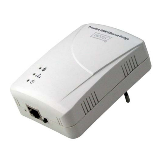
- Page 1 Powerline Ethernet Bridge User’s Manual (DN-15019-2)
-
Page 2: Table Of Contents
Index 1. Powerline Networking Installation ..........................2 1.1 Simple step to install Powerline Networking ..................2 1.2 Application Block Diagram ........................3 1.3 Benefits ..............................5 1.4 Features ..............................5 1.5 Package Contents ..........................5 1.6 LED Definitions ............................6 1.7 System Requirements ........................... -
Page 3: Powerline Networking Installation
1. Powerline Networking Installation 1.1 Simple step to install Powerline Networking... -
Page 4: Application Block Diagram
1.2 Application Block Diagram 1.2.1 Internet ADSL with one computer via power outlet 1.2.2 Online game via power outlet... - Page 5 1.2.3 Internet ADSL and Home Networking via power outlet...
-
Page 6: Benefits
1.3 Benefits ‧Data transfers at up to 200 Mbps over the household power circuit ‧Ranges of 200 meters ‧No need new wires for Home networking ‧Deliver the benefits of Ethernet without the wiring expense ‧Send even large files between PCs without long waits ‧High-speed Internet and DVD-quality video streaming ‧Fully compliant with IEEE 802.3, IEEE 802.3u ‧Privacy through DES encryption... -
Page 7: Led Definitions
1.6 LED Definitions State Description Powerline network activity. Powerline Search or no Powerline network activity. Ethernet connection is OK. Ethernet Flashing Data transfer. No link to Ethernet. Power on. POWER Powerline off or failure. Button Description Button can auto secure and group the Powerline devices. Secure Push this button can reset to the factory default settings. -
Page 8: Powerline Networking Utility
2. Powerline Networking Utility Note The Powerline Device can auto detect the other Powerline bridges which plug in the same power circuit, you don’t need to use this Powerline utility except you want to encryption all the Powerline devices as the same group or you can not access the other computers. - Page 9 Figure 2.1.1. Figure 2.1.2.
- Page 10 Common Features of Tabbed Windows Status Bar The status bar, along the bottom of each window, contains five fields that provide important network information. • The first field contains the status of the Device Manager in respect to connection to a Powerline device. ‘Connected’...
-
Page 11: User Interface - Network Information Tab
2.1 User Interface - Network Information Tab This window is an Operation Analysis window that reveals Network information in three categories: CCo Information, Connected STA Information and Topology. 2.1.1. Topology The ‘Topology’ group shows the TEI, MAC Address, Bridged MAC Address and the transmit (Tx) and receive (Rx) Coded and Raw PHY rates for all nodes on the network (other than the local STA). -
Page 12: User Interface - Encryption Tab
2.2 User Interface - Encryption Tab This Encryption window is used to set or change the network password on a remote device identified by its DAK password. Clicking the ‘Set’ button sets the entered passwords. If the DAK password field is left blank, then clicking the ‘Set’... -
Page 13: User Interface - Link Information Tab
2.3 User Interface - Link Information Tab 2.3.1. Link Characteristics Box The context of the link is identified with the Source and Destination address boxes in the Link Characteristics group box. The Source Address defaults to the address of the device selected in the Device Selection box on the lower left of the tab and the Destination Address is selected from a drop down list. -
Page 14: User Interface - Connection Information Tab
2.4 User Interface - Connection Information Tab The Connection Information window is used to acquire statistics for both transmit and receive operations in the local or remote network. 2.4.1. Connection Select CSMA : the Destination Address (DA) drop-down menu may be used to select ALL devices or specific devices in the network. - Page 15 Figure 4: Connection Information Tab...
-
Page 16: User Interface - Qos Tab
2.5 User Interface - QoS Tab QoS requirements are different for various data types such as streaming video or music, voice and raw data. To provide higher QoS for streaming data, priority levels can be set using tags at the beginning of data frames. Virtual Local Area Network (VLAN) 802.1p priority tags on Ethernet frames are used to specify 8 (0 –... - Page 17 2.5.3 Default CAP The ‘Default CAP’ group allows for default priority mapping of packets that do not have a VLAN or TOS bit (or if these are disabled). Settings are available for Unicast (directed to a host). IGMP (default CAP 3): sets the channel access priority for IGMP frames - these are the group management frames, not the stream data.
- Page 18 2.5.4. IGMP The ‘IGMP’ group includes controls to disable the query timeouts. Checking the ‘Override Defaults’ box will enable the other boxes as choices. 2.5.5. Priority TTL Value The ‘Priority TTL Value’ determines the life span (Time to live) of each packet in the buffer of the AV device that will be sent over the powerline subsequently.
-
Page 19: Push Button Setting
3. Push Button Setting There are 2 buttons in this device, one is Reset button the other is Secure button. Reset: Push this button can reset to the factory default settings. Be careful, when you press the reset button, please make sure unplug (remove) the Ethernet cable (RJ-45cable) first, and then press the reset button. After press the reset button (the time need <... - Page 20 Possible Use Case Scenario 1: Unassociated device joining existing AVLN Possible Use Case Scenario 2: Two devices joining to form new AVLN Before this scenario begin, please make sure to press each device secure button > 10 sec till all LEDs re-flash to generate the random network password key first.
-
Page 22: Trouble Shooting
4. Trouble Shooting 1. Why my utility can not work properly after finish install steps? Ans: Please follow the steps to check the problem. Check the Control panel for Microsoft .NET Framework install status, if you don’t install this, please install it.
Need help?
Do you have a question about the DN-15019-2 and is the answer not in the manual?
Questions and answers