Table of Contents
Advertisement
Quick Links
®
Installation and Operation Manual
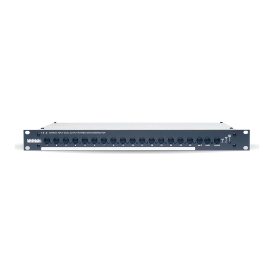
16 x 2 (SS 16.2)
Sixteen Input, Dual Output Stereo Switcher/Router
Firmware Version v 1.08
Manual Update: 7/1/2004
Due to the dynamic nature of product design, the information contained in this
document is subject to change without notice. Broadcast Tools, Inc., assumes no
responsibility for errors and/or omissions contained in this document. Revisions
of this information or new editions may be issued to incorporate such changes.
Broadcast Tools® is a registered trademark of Broadcast Tools, Inc.
Copyright, 1989 - 2005 by Broadcast Tools, Inc. All rights reserved.
No part of this document may be reproduced or distributed without permission.
Visit www.broadcasttools.com for important product update information.
Advertisement
Table of Contents

Related Manuals for Broadcast Tools SS 16.2


Summary of Contents for Broadcast Tools SS 16.2
- Page 1 Manual Update: 7/1/2004 Due to the dynamic nature of product design, the information contained in this document is subject to change without notice. Broadcast Tools, Inc., assumes no responsibility for errors and/or omissions contained in this document. Revisions of this information or new editions may be issued to incorporate such changes.
-
Page 2: Safety Information
SS 16.2 Installation and Operation Manual INTRODUCTION CAUTION! Thank you for your purchase of a Broadcast Tools, Inc., 16 x 2, Sixteen Input, Dual Broadcast Tools® Output Stereo Switcher/Router that we will refer to throughout the manual as the 16 x 2. -
Page 3: Product Description
Some of the applications of the 16 x 2 include: Studio selection and routing; Audio WEBSITE: processing selection; Exciter input selection; Remote broadcast input selection; STL source selection; Automation source selection; EAS audio switching; ISDN or Visit our web site for Phone hybrid feed selection;... -
Page 4: Front Panel Description
SS 16.2 Installation and Operation Manual FRONT PANEL DESCRIPTION SOURCE SWITCHES Each switch represents an input to be routed to either or both of the outputs. High quality tactile switches will give the user years of dependable service. Each switch has an associated LED indicator, which will illuminate when that particular source is routed to either or both of the outputs. -
Page 5: Installation
SS 16.2 Installation and Operation Manual INSTALLATION Installation of the 16 x 2 in high RF environments should be performed with care. Shielded cable is suggested for all control, audio inputs and outputs. All shields should be tied to the EGND terminals. The station ground should be connected to the chassis ground screw located on the far right side of the 16 x 2 as viewed from the rear. - Page 6 SS 16.2 Installation and Operation Manual INSTALLATION Continued NOTE: STEP 3: BENCH TEST and OPTIONS When the unit is in Place each unit on a workspace and connect power to the unit. Check to see if LED “Programming” mode, #1 (Switch 1) and the Pwr/Ser LED are lit (Source one is the power-up factory the “Channel 16”...
- Page 7 SS 16.2 Installation and Operation Manual INSTALLATION Continued Set PIP Mode: stretch positive pulses to minimum 1 second Set PIP Mode: stretch positive pulses to minimum of 2 seconds Set PIP Mode: stretch positive pulses to minimum of 4 second OFF = Allows selection of power up channel.
- Page 8 SS 16.2 Installation and Operation Manual INSTALLATION Continued Modular connectors point of view. Serial Burst Mode Commands The unit is controlled via the Burst mode. The baud rates are selected on page 6. The 16 x 2 may be serially controlled via the multi-drop RS-232 port. Commands may be entered with a short form code (burst mode).
- Page 9 SS 16.2 Installation and Operation Manual INSTALLATION Continued NOTE: Audio Switch Control Commands *uiio - Apply input “ii” to output “o” When the ID is set to 0 *uiiA - Apply input “ii” to both outputs and the switcher is con- *uiiMA - Mute input “ii”...
-
Page 10: Step 5: Connect Your Equipment
SS 16.2 Installation and Operation Manual STEP 4: MOUNTING Mount the unit in a rack or desktop, allowing adequate airflow for cooling. STEP 5: CONNECT YOUR EQUIPMENT The 16 x 2 interfaces to your equipment (sources and loads) through the rear panel pluggable screw terminals. -
Page 11: Specifications
SS 16.2 Installation and Operation Manual STATUS The status signals from the front panel indicator LEDs are supplied through the “REMOTE” control connector as individual open collectors. This may provide sta- tus to a remote control point to indicate which source is selected. The status output for the selected output will go low, providing a return for an LED indicator or TTL/CMOS logic. - Page 12 SS 16.2 Installation and Operation Manual INTERFACING: Audio - Pluggable screw terminals (Euro). Remote Control - Male 37 pin “D” connector. RS-232 - 4C6P Modular. All mating connectors, modular cable and adapter supplied. POWER REQUIREMENTS: 9 Vac, 500 ma. 120 Vac 50-60 hz transformer.
- Page 13 If Broadcast Tools is notified, in writing, of a failure of any item manufactured by Broadcast Tools to conform to the foregoing Limited Warranty within one (1) year following the date of the Buyer’s acquisition of the item, and if the item is returned to Broadcast Tools in accordance with Broadcast Tools’...
Need help?
Do you have a question about the SS 16.2 and is the answer not in the manual?
Questions and answers