Table of Contents
Advertisement
Quick Links
®
Installation and Operation Manual
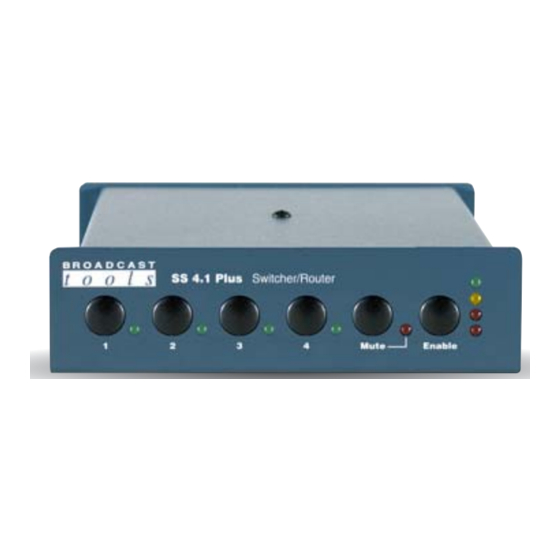
SS 4.1 Plus
Four Input, Single Output Stereo Switcher/Router
Firmware Version 1.10
Manual Update: 06/21/2011
Due to the dynamic nature of product design, the information contained in this
document is subject to change without notice. Broadcast Tools, Inc., assumes no
responsibility for errors and/or omissions contained in this document. Revisions
of this information or new editions may be issued to incorporate such changes.
Broadcast Tools® is a registered trademark of Broadcast Tools, Inc.
tiny TOOLS™ is a trademark of Broadcast Tools, Inc.
All Sentinel™ labeled products are a trademark of Broadcast Tools, Inc.
Copyright ® 1989 - 2009 by Broadcast Tools, Inc. All rights reserved.
No part of this document may be reproduced or distributed without permission.
Visit www.broadcasttools.com for important product update information.
Advertisement
Table of Contents

Related Manuals for Broadcast Tools SS 4.1 Plus


Summary of Contents for Broadcast Tools SS 4.1 Plus
- Page 1 Manual Update: 06/21/2011 Due to the dynamic nature of product design, the information contained in this document is subject to change without notice. Broadcast Tools, Inc., assumes no responsibility for errors and/or omissions contained in this document. Revisions of this information or new editions may be issued to incorporate such changes.
-
Page 2: Table Of Contents
SS 4.1 Plus Installation and Operation Manual Table of Contents Section Title Page # Introduction............3 Safety Information . -
Page 3: Introduction
SS 4.1 Plus Installation and Operation Manual INTRODUCTION CAUTION! Thank you for your purchase of a Broadcast Tools® SS 4.1 Plus, Four Input, Single Broadcast Tools® Output Stereo Switcher/Router (referred to as the SS 4.1 Plus throughout this manu- Products, as with any al). -
Page 4: Product Description
• Non-selected sources are terminated with 10K W load resistors. May be removed. • The SS 4.1 Plus may be set on a desktop, mounted on a wall or up to three units on one RA-1 rack shelf. -
Page 5: Front Panel Description
Pulsing the “MUTE” input to ground (low) would turn off the out- put of the SS 4.1 Plus until a front panel source switch is pressed, a remote control input is activated, the unit is powered up and/or a serial command is received from a PC or other serial device. -
Page 6: Installation Guidelines
Installation Guidelines CAUTION! It is recommended that all cables connected to the SS 4.1 Plus be looped through fer- rite cores to suppress RF. Surge protection with RF filtering such as the Tripp Lite “ISOBAR 4” is also suggested for the power transformer. The purchase of an inex- pensive uninterruptible power supply (UPS) will provide back up in case of power outages. - Page 7 SS 4.1 Plus Installation and Operation Manual STEP 3: BENCH TEST and OPTIONS Place each unit on a workspace and connect power to the unit. Check to see if LED #1 (Channel 1) and the PWR LED are lit (Source one is the power-up factory default).
- Page 8 The front panel functions are brought out through the rear panel “REMOTE” (Inx) connector TB 4, providing a means of controlling the SS 4.1 Plus from a remote point. The channel select inputs may be connected to any remote pair of switch con- tacts and ground, such as external relays, switches, open-collector circuits, contact closures or 5-volt TTL/CMOS logic signals.
- Page 9 Connecting the remote control, PIP / Trigger Inputs and OC’s / SS Relay Most front panel functions of the SS 4.1 Plus may be remote controlled via the plug- gable euroblock screw terminals located on the rear panel. The SS 4.1 Plus accepts momentary contact closures (sustained, if break before make);...
- Page 10 117 vac and the cable end of the transformer into the power recep- tacle on the SS 4.1 Plus. The protocol is as follows: 2400, 4800, 9600, 38400, 8N1. Flow control should be set to NONE, emulation to ANSI and the mode should be set to DIRECT TO COMx (x = the available com port).
- Page 11 SS 4.1 Plus Installation and Operation Manual Menu: The menu allows the selection of PIP (eight triggers) hold time, silence sensor delay and restore time, step time, the selection of the last channel in the step, front panel lock, audio channel selection with status and audio status.
-
Page 12: Specifications
SS 4.1 Plus Installation and Operation Manual Specifications Inputs/Outputs: Any input level and impedance can be used. Inputs may be bal- anced or unbalanced. Output levels, impedance, distortion, noise and balancing will match that of the selected input. Switching Method: Passive, sealed relays utilizing 2-form-C bifurcated - crossbar silver alloy with gold overlay contacts. -
Page 13: Warranty
If Broadcast Tools is notified, in writing, of a failure of any item manufactured by Broadcast Tools to conform to the foregoing Limited Warranty within one (1) year following the date of the Buyer’s acquisition of the item, and if the item is returned to Broadcast Tools in accordance with Broadcast Tools’...
Need help?
Do you have a question about the SS 4.1 Plus and is the answer not in the manual?
Questions and answers