Table of Contents
Advertisement
Quick Links
®
P R O B L E M S O LV E D
Installation and Operation Manual
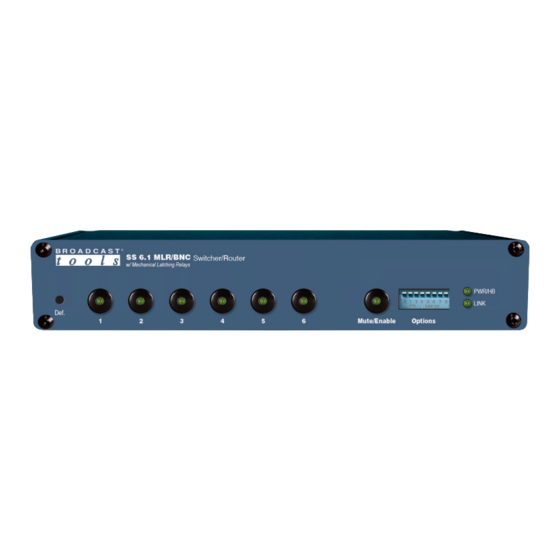
SS 6.1 MLR/BNC
BNC Switcher/Router with Mechanical Latching Relays
Firmware Version 0.2 and above
Manual update: 5/16/2024
If you need a firmware upgrade, contact Broadcast Tools®
No part of this document may be reproduced or distributed without permission.
ALL SPECIFICATIONS AND FEATURES FOR THIS PRODUCT ARE SUBJECT TO
CHANGE WITHOUT NOTICE
NOTE: We recommend the use of Chrome, Firefox or Safari as your browser.
Due to the dynamic nature of product design, the information contained in this
document is subject to change without notice. Broadcast Tools, Inc., assumes no
responsibility for errors and/or omissions contained in this document. Revisions
of this information or new editions may be issued to incorporate such changes.
Broadcast Tools® is a registered trademark of Broadcast Tools, Inc.
All Sentinel® labeled products are registered trademarks of Broadcast Tools, Inc.
Copyright® 1989 - 2024 by Broadcast Tools, Inc. All rights reserved.
No part of this document may be reproduced or distributed without permission.
Broadcast Tools is a Veteran Owned Business
Visit www.broadcasttools.com for important product update information.
Advertisement
Table of Contents

Subscribe to Our Youtube Channel
Related Manuals for Broadcast Tools SS 6.1 MLR/BNC


Summary of Contents for Broadcast Tools SS 6.1 MLR/BNC
- Page 1 NOTE: We recommend the use of Chrome, Firefox or Safari as your browser. Due to the dynamic nature of product design, the information contained in this document is subject to change without notice. Broadcast Tools, Inc., assumes no responsibility for errors and/or omissions contained in this document. Revisions of this information or new editions may be issued to incorporate such changes.
-
Page 2: Table Of Contents
SS 6.1 MLR/BNC Installation and Operation Manual Table of Contents Section Title Page # Introduction..........3 Safety Information . -
Page 3: Introduction
If you are unfamiliar with this type of equip- NOTE: ment, please contact a properly qualified engineer to handle the installation, and setup of the SS 6.1 MLR/BNC. Broadcast Tools, Inc., is unable to support NON- This manual should be Broadcast... -
Page 4: Product Overview
Inputs may be balanced or unbalanced, while output levels, impedance, distortion, noise, and balancing will match that of the selected input. The SS 6.1 MLR/BNC can be controlled and monitored locally and/or with simple contact closures to ground, front panel switches, multi-drop RS-232 serial or Ethernet (TCP/UDP) commands. -
Page 5: Installation
UPS Standby Power System We recommend that you connect your SS 6.1 MLR/BNC to a UPS standby power system. A UPS, like the BE600M1 from APC helps to minimize the risk to the SS 6.1 MLR/BNC and provides power during a power outage. -
Page 6: I/O Connections
1 would turn ON Input 1 and turn OFF any previously additional information. selected input on SS 6.1 MLR/BNC until a front panel source switch is pressed, a different remote-control input is activated, the unit is powered up and/or a serial/Ethernet command is received from a PC or other device. -
Page 7: Relay Outputs
SS 6.1 MLR/BNC Installation and Operation Manual Relay Outputs The SS 6.1 MLR/BNC has six normally open relay outputs that are used to indicate channel selection status. K1 indicates for Input 1, K2 indicates for Input 2, etc. The status relay output for the selected channel will connect to the relay common pro- viding a return for an LED indicator, TTL/CMOS logic, or relay. -
Page 8: Rs-232 Serial Port
SS 6.1 MLR/BNC Installation and Operation Manual RS-232 Serial Port (RJ-11 Jack) This RJ-11 jack is used to connect the SS 6.1 MLR/BNC to a computer’s COM port for RS-232 serial operation using the included reverse modular cable with 9-pin “S9”... -
Page 9: Configuration Dip-Switch Setup
SS 6.1 MLR/BNC Installation and Operation Manual Configuration DIP-Switch Setup Follow the tables below for front panel dipswitch (SW11) configuration options. NOTE: After changing any DIP-switch, please repower the unit. Note: To select an input at power-up with SW9-6 ON, hold down the front panel push-button for the desired input channel or mute until the front panel LEDs flash. -
Page 10: Rs-232 Control
SS 6.1 MLR/BNC Installation and Operation Manual SERIAL/ETHERNET OPERATION RS-232 Serial Control Connect one end of the modular cable to the RJ11 jack on the rear panel of the prod- uct and the other end to the RJ11 to the jack on the “S9” 9-pin female D-sub adapter. -
Page 11: Menu Operation
Delay xx seconds before processing the next command. *uDLxxx Delay xxx seconds before processing next command. Menu Operation Broadcast Tools(R) SS 6.1 MLR/BNC, v0.2 - Setup Menu 1 - Lock/Unlock Front Panel - Now:UNLOCKED S - Turn ON audio input... -
Page 12: Ethernet Setup And Operation
SS 6.1 MLR/BNC Installation and Operation Manual Ethernet Setup and Operation CAUTION! Ethernet “Quick Start” Guide NEVER DOWNLOAD FIRMWARE UPDATES CAUTION! If you are not familiar with Ethernet enabled equipment, it may be use- OR CHANGES TO ful to contact your IT department, network administrator or network consultant for THE WEB SERVER assistance. - Page 13 SS 6.1 MLR/BNC Installation and Operation Manual Step 2: Under Advanced Network Settings click Change adapter settings. The Network Connections windows will pop up, as shown below. Step 3: Right click on the icon labeled Local Area Connection or Ethernet. A menu will appear.
- Page 14 SS 6.1 MLR/BNC Installation and Operation Manual Step 4: On the Local Area Connection Properties page, double click on Internet Protocol (TCP/IPv4) to display properties. Step 5: Before making any changes to the network settings, write down the current WEBSITE:...
-
Page 15: Connecting Via The Ethernet Port
4. In PuTTY configuration > Terminal > Line discipline options set Local echo “Force on” and Local line editing to “Force off”. 5. Click okay to connect to the SS 6.1 MLR/BNC and type *0mm into the terminal window and press return to bring up the Menu. See: “Serial/Ethernet” section of this manual. -
Page 16: Changing Network Settings
1. Connect the supplied GRAY colored XOVER cable between the PC’s Ethernet port and the products “LAN/NET” network RJ45 jack. 2. Connect the included power supply to the SS 6.1 MLR/BNC. Verify that the green PWR LED is lit and the green “LINK” LED to the left of the “LAN/NET”... - Page 17 SS 6.1 MLR/BNC Installation and Operation Manual 6. The default work mode is TCP Server, TCP Client, UDP Server and UDP Client are also available. To change the TCP port choose “Serial Port” from the side bar and change the “Local Port Number” setting: 7.
-
Page 18: Specifications
SS 6.1 MLR/BNC Installation and Operation Manual Specifications Inputs/Outputs: Any input level and impedance can be used. Inputs may be bal- anced or unbalanced. Output levels, impedance, distortion, noise, and balancing will match that of the selected input. Switching Method: Passive. -
Page 19: Warranty
If Broadcast Tools is notified, in writing, of a failure of any item manufactured by Broadcast Tools to conform to the foregoing Limited Warranty within one (1) year following the date of the Buyer’s acquisition of the item, and if the item is returned to Broadcast Tools in accordance with Broadcast Tools’... - Page 20 SS 6.1 MLR/BNC Installation and Operation Manual APPENDIX e-mail: voice: fax: support@broadcasttools.com 360.854.9559 866.783.1742...
- Page 21 SS 6.1 MLR/BNC Installation and Operation Manual APPENDIX e-mail: voice: fax: support@broadcasttools.com 360.854.9559 866.783.1742...
-
Page 22: Functional Diagram
SS 6.1 MLR/BNC Installation and Operation Manual SS 6.1 MLR/BNC 6-Input Switcher/Router w/ Mechanical Latching Relays Functional Diagram Inputs Common Output Relay Control Input Select +7 Input Remote Control +7 SPST Relay 1-6 Inputs 1-6 Micro Mute Controller RS-232 Serial...
Need help?
Do you have a question about the SS 6.1 MLR/BNC and is the answer not in the manual?
Questions and answers