Table of Contents
Advertisement
Quick Links
Installation and Operation Manual
Switcher/Router with Mechanical Latching Relays
Firmware version 1.0 and higher. If you need a firmware upgrade, contact Broadcast Tools®.
No part of this document may be reproduced or distributed without permission.
ALL SPECIFICATIONS AND FEATURES FOR THIS PRODUCT ARE SUBJECT TO
NOTE: We recommend the use of Chrome, Firefox or Safari as your browser.
Due to the dynamic nature of product design, the information contained in this
document is subject to change without notice. Broadcast Tools, Inc., assumes no
responsibility for errors and/or omissions contained in this document. Revisions
of this information or new editions may be issued to incorporate such changes.
Broadcast Tools® is a registered trademark of Broadcast Tools, Inc.
All Sentinel® labeled products are registered trademarks of Broadcast Tools, Inc.
Copyright® 1989 - 2017 by Broadcast Tools, Inc. All rights reserved.
No part of this document may be reproduced or distributed without permission.
Visit www.broadcasttools.com for important product update information.
P R O B L E M S O LV E D
Universal 4.1 MLR/Serial
Manual update: 7/1/2017
CHANGE WITHOUT NOTICE
®
Advertisement
Table of Contents

Related Manuals for Broadcast Tools Universal 4.1 MLR/Serial


Summary of Contents for Broadcast Tools Universal 4.1 MLR/Serial
- Page 1 Switcher/Router with Mechanical Latching Relays Manual update: 7/1/2017 Firmware version 1.0 and higher. If you need a firmware upgrade, contact Broadcast Tools®. No part of this document may be reproduced or distributed without permission. ALL SPECIFICATIONS AND FEATURES FOR THIS PRODUCT ARE SUBJECT TO CHANGE WITHOUT NOTICE NOTE: We recommend the use of Chrome, Firefox or Safari as your browser.
-
Page 2: Table Of Contents
Universal 4.1 MLR Installation and Operation Manual Table of Contents Section Title ........Page # Safety Information . -
Page 3: Safety Information
IAL. Any attempt to install this device by a person who is not technically quali- fied could result in a hazardous condition to the installer or other personnel or damage to the UNIVERSAL 4.1 MLR/SERIAL or other equipment. Please ensure that proper safety precautions have been taken before installing this device. If you are unfamiliar with this type of equipment, please contact a properly qualified engineer to handle the installation and setup of the UNIVERSAL 4.1 MLR/SER-... -
Page 4: Product Overview
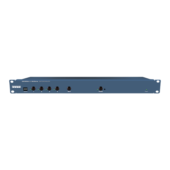
The Universal 4.1 MLR/Serial is a transparent four input, one output switcher/router with mechanical latching relays designed to pass AES/EBU digital audio or stereo analog audio signals. The Universal 4.1 MLR/Serial is perfect for all types of passive signal switching via front panel button, USB/RS-232 serial, and contact closures/logic remote control. -
Page 5: Installation
UPS Standby Power System We recommend that you connect your UNIVERSAL 4.1 MLR/SERIAL to a UPS system. A UPS helps minimize the risk to the UNIVERSAL 4.1 MLR/SERIAL and provides power during a power outage. NOTE: If power is lost, the last selected channel is passed to the output. -
Page 6: Power/Connector Pin-Outs
USB Port This type B USB port is used to connect the Universal 4.1 MLR/Serial to a com- puter’s USB port using the supplied USB A/B cable. When you first plug the Universal 4.1 MLR/Serial into your PC, it should automatically install the correct FTDI USB Serial “Virtual COM port”... -
Page 7: Audio Inputs And Outputs
* StudioHub+ “DC-LINK” allows +/-15 VDC and Ground to pass on pin 8, 7, and 4 (respectively) of the RJ45. These pins are connected in parallel across all RJ45s on the Universal 4.1 MLR/Serial. For AES/EBU signals please use AES/EBU digital audio qualified cable. -
Page 8: Remote Control Inputs
For example, in Remote Control mode, pulsing the “I2” input to ground would nected to the chassis switch Input 2 to the output of the Universal 4.1 MLR/Serial and remain switched using a 20 to 24-gauge that way until a front panel source switch is pressed, a different remote-control input wire. -
Page 9: Configuration Dip-Switches
Universal 4.1 MLR Installation and Operation Manual Configuration Dip-switch Setup Follow the tables below for SW9 dip-switch configuration options. Unit ID SW9-1 SW9-2 ID 0* ID 1 ID 2 ID 3 Baud Rate SW9-3 9600* 38400 Operation Mode SW9-4 Remote Control * •... -
Page 10: Usb/Serial Setup
Start a serial terminal application like Tera Term, PuTTY, or HyperTerminal config- ured for the COM port the Universal 4.1 MLR/Serial is connected to at 9600 baud ,8, N,1 flow control to NONE, Emulation set to ANSI, and local character echo enabled. -
Page 11: Usb/Serial Control/Commands
Universal 4.1 MLR Installation and Operation Manual USB/Serial Control The switcher may be controlled and monitored by the burst serial string commands listed below or by the embedded setup menu. Command Key Where: < * > Denotes start of string character <... -
Page 12: Usb/Serial Menu
Universal 4.1 MLR Installation and Operation Manual Menu Operation Type *0mm to access the setup menu. To select a menu function, simply enter the letter on the left side of the menu and wait for the prompt. Example: Type the let- ter “S”... -
Page 13: Specifications
Universal 4.1 MLR Installation and Operation Manual SPECIFICATIONS Inputs/Outputs: Any input level and impedance can be used. Inputs may be balanced or unbalanced. Output levels, impedance, distortion, noise and balancing will match that of the selected input. Switching Method: Passive. Mechanical latching sealed relays utilizing 2-form-C bifurcated-crossbar silver alloy with gold overlay contacts. -
Page 14: Warranty
If Broadcast Tools is notified, in writing, of a failure of any item manufactured by Broadcast Tools to conform to the foregoing Limited Warranty within one (1) year following the date of the Buyer’s acquisition of the item, and if the item is returned to Broadcast Tools in accordance with Broadcast Tools’... - Page 15 Product_Name Installation and Operation Manual APPENDIX e-mail: voice: fax: support@broadcasttools.com 360.854.9559 866.783.1742...
- Page 16 Product_Name Installation and Operation Manual APPENDIX e-mail: voice: fax: support@broadcasttools.com 360.854.9559 866.783.1742...
- Page 17 Product_Name Installation and Operation Manual APPENDIX e-mail: voice: fax: support@broadcasttools.com 360.854.9559 866.783.1742...
Need help?
Do you have a question about the Universal 4.1 MLR/Serial and is the answer not in the manual?
Questions and answers