Table of Contents
Advertisement
Quick Links
®
Installation and Operation Manual
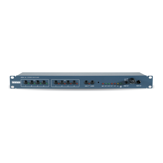
SS 4.2
Four Input, Dual Output Stereo Audio Matrix Switcher
Software Version 1.21
Manual update 8/29/04
Due to the dynamic nature of product design, the information contained in this
document is subject to change without notice. Broadcast Tools, Inc., assumes no
responsibility for errors and/or omissions contained in this document. Revisions
of this information or new editions may be issued to incorporate such changes.
Broadcast Tools® is a registered trademark of Broadcast Tools, Inc.
Copyright, 1989 - 2005 by Broadcast Tools, Inc. All rights reserved.
No part of this document may be reproduced or distributed without permission.
Visit www.broadcasttools.com for important product update information.
Advertisement
Table of Contents

Related Manuals for Broadcast Tools SS 4.2


Summary of Contents for Broadcast Tools SS 4.2
- Page 1 Manual update 8/29/04 Due to the dynamic nature of product design, the information contained in this document is subject to change without notice. Broadcast Tools, Inc., assumes no responsibility for errors and/or omissions contained in this document. Revisions of this information or new editions may be issued to incorporate such changes.
-
Page 2: Table Of Contents
SS 4.2 Installation and Operation Manual Table of Contents Section Title Page # Introduction ..........2 Safety Information . -
Page 3: Introduction
SS 4.2 Installation and Operation Manual INTRODUCTION CAUTION! Thank you for your purchase of a Broadcast Tools® SS 4.2 Four Input, Dual Broadcast Tools® Output Stereo Audio Matrix Switcher (referred to as the SS 4.2 throughout this Products, as with any manual). - Page 4 2 stereo plus 2 mono outputs. Matrix switching allows any or all inputs to be assigned to any or all outputs. The SS 4.2 may be controlled via front panel switch- es, contact closures, 5-volt TTL/CMOS logic and/or the multi-drop RS-232 serial port.
- Page 5 SS 4.2 Installation and Operation Manual FUNCTION DESCRIPTION Front Panel: The SS 4.2 is a 1-rack unit device (19”w x 1.75”h x 4.8”d). The front panel sup- ports ten selection switches, 16 LED indicators, headphone selection switch, _” jack and level control.
- Page 6 Silence Sensor: The SS 4.2 contains individual silence sensors for each of stereo output channels. For each channel, a detector monitors the sum of each stereo channel. The factory default delay is set at 10 seconds, with a threshold of -30 dB, while the restore time is set at 10 seconds.
- Page 7 • Software control Relay Outputs, 4 Port Output Control: The SS 4.2 contains 4 spst (normally open) relays. Each relay may be latched on, latched off or momentarily turned on by a non-dedicated computer. The “pulse” time may be set from 100 msec to 9.9 seconds. The default pulse length is one-sec- ond.
-
Page 8: Installation Guidelines
INSTALLATION GUIDELINES Inspection: Please examine your SS 4.2 carefully for any damage that may have been sustained during shipping. If any is noted, please notify the shipper immediately and retain the packaging for inspection by the shipper. The package contains the SS 4.2, 16.5 vac @ 600ma power transformer, Installation manual and a reversed modular serial cable with a (S9) 9 pin D-Sub adapter. -
Page 9: Mounting
Mounting: nel. The station ground The SS 4.2 is designed to be rack mounted in a standard 19” rack. It should be should be connected to mounted in an area that is accessible from the rear and preferably away from sources the chassis ground of heat. -
Page 10: Adjusting Input And Output Levels
SS 4.2 Installation and Operation Manual It is recommended that all cables connected to the SS 4.2 be looped through fer- rite cores to suppress RF. Surge protection with RF filtering such as the Tripp Lite “ISOBAR 4” is also suggested for the power transformer. The purchase of an inexpensive uninterruptible power supply (UPS) will provide back up in case of power outages. -
Page 11: Connecting The Serial Port
Connecting the RS-232 Serial Port: Use the provided modular (S9) 9-pin D-sub connector adapter and reversed modu- Visit our web site for lar cord to connect the SS 4.2’s serial connector to your serial port. product updates and additional information... - Page 12 Multiple SS 4.2’s may be cascaded serially to operate from the same serial port. The first step is to assign ID’s to each SS 4.2. One suggestion is to assign 1 to the first SS 4.2 and 2 to the second switcher. The second step is to parallel the serial ports of the SS 4.2’s.
-
Page 13: Set-Up Commands
SS 4.2 Installation and Operation Manual Serial Burst Mode Commands: Burst mode allows a computer or ASCII terminal to control and interrogate the unit. This section defines all burst mode commands. Each burst mode commands starts with an asterisk (“*”). Next is a single decimal digit that corresponds to the unit (ID) address 0-3. - Page 14 SS 4.2 Installation and Operation Manual *uCSAtttt - Set silence sensor time delay to tttt seconds (0002 – 9999), 0000 = OFF *uCSBtttt - Set silence sensor restore delay to tttt seconds (0002 – 9999), 0000 = OFF *uCSDttt - Ignore, send OK...
-
Page 15: Output Port Control
SS 4.2 Installation and Operation Manual Information Retrieval Commands: *POLL - Respond with unit (ID) address in appropriate time slot. If there are multiple units on the line, each will respond with a different delay after receipt of this command. - Page 16 SS 4.2 Installation and Operation Manual Audio and remote connections: TB 9 The bottom connector has two functions, depending on the position of SW13-7 Com. N.O. N.O. N.O. N.O. PIP1 PIP2 PIP3 PIP4 PIP5 PIP6 PIP7 PIP8 PIP9 PIP10 PIP11...
-
Page 17: Specifications
SS 4.2 Installation and Operation Manual SPECIFICATIONS Input Levels: Max + 27 dBu, balanced, bridging. > 20k W Output Levels: Stereo balanced outputs 1 & 2, +24 dBu. @ 600 W. / +27dbu @ 10KW Monaural balanced outputs 1 & 2, +24 dBu. @ 600 W. / +27dbu @ 10KW Headphone output, 4.7 W. -
Page 18: Warranty
If Broadcast Tools is notified, in writing, of a failure of any item manufactured by Broadcast Tools to conform to the foregoing Limited Warranty within one (1) year following the date of the Buyer’s acquisition of the item, and if the item is returned in to Broadcast Tools in accordance with Broadcast Tools’...
Need help?
Do you have a question about the SS 4.2 and is the answer not in the manual?
Questions and answers