Table of Contents
Advertisement
Quick Links
®
Installation and Operation Manual
SS 4.1 III
Four Input, Single Output Stereo Switcher/Router
Manual Update: 02/13/07
Due to the dynamic nature of product design, the information contained in this
document is subject to change without notice. Broadcast Tools, Inc., assumes no
responsibility for errors and/or omissions contained in this document. Revisions
of this information or new editions may be issued to incorporate such changes.
Broadcast Tools® is a registered trademark of Broadcast Tools, Inc.
Copyright„ 1989 - 2007 by Broadcast Tools, Inc. All rights reserved.
No part of this document may be reproduced or distributed without permission.
Visit www.broadcasttools.com for important product update information.
Advertisement
Table of Contents

Related Manuals for Broadcast Tools SS 4.1 III


Summary of Contents for Broadcast Tools SS 4.1 III
- Page 1 Manual Update: 02/13/07 Due to the dynamic nature of product design, the information contained in this document is subject to change without notice. Broadcast Tools, Inc., assumes no responsibility for errors and/or omissions contained in this document. Revisions of this information or new editions may be issued to incorporate such changes.
-
Page 2: Table Of Contents
SS 4x1 III Installation and Operation Manual Table of Contents Section Title Page # Introduction ..........3 Safety Information . -
Page 3: Introduction
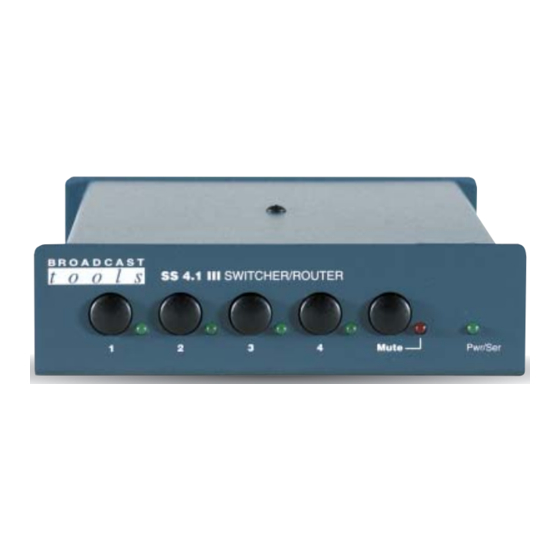
SS 4x1 III Installation and Operation Manual INTRODUCTION CAUTION! Thank you for your purchase of a Broadcast Tools® SS 4.1 III, Four Input, Broadcast Tools® Single Output Stereo Switcher/Router (referred to as the SS 4.1 III throughout Products, as with any this manual). -
Page 4: Product Description
The SS 4.1 III passively switches or routes a variety of electrical signals to a desti- nation. The SS 4.1 III selects any one of 4 stereo inputs to a single stereo output. The SS 4.1 III provides PASSIVE switching through gold contact relays. The passive switching means that the unit can route a signal in both directions (any one of 4 stereo inputs to a single destination, or a single source to any one of 4 destinations). -
Page 5: Rear Panel Description
SS 4.1 III. Pulsing the “MUTE” input to ground (low) would turn off the output of the SS 4.1 III until a front panel source switch is pressed, a remote control input is activated or the unit is powered up. -
Page 6: Installation Guidelines
SS 4x1 III Installation and Operation Manual INSTALLATION GUIDELINES CAUTION! It is recommended that all cables connected to the SS 4.1 III be looped through fer- Installation of the SS rite cores to suppress RF. Surge protection with RF filtering such as the Tripp Lite 4.1 III in high RF envi-... - Page 7 Mount the unit in a rack or desktop, allowing adequate airflow for cooling. STEP 5: CONNECT YOUR EQUIPMENT The SS 4.1 III interfaces to your equipment (sources and loads) through the rear panel pluggable screw terminals. Follow the legends for the desired audio input, output and remote control connections, which appear on the rear side of the chassis.
- Page 8 The supplied reversed modular cable and 9-pin (S9) D-sub adapters may be con- nected to the SS 4.1 III’s rear panel modular connector. Plug in the D-sub adapter into your computer’s serial port. Plug the supplied wall transformer into a source of 117 vac and the cable end of the transformer into the power receptacle on the SS 4.1...
- Page 9 The front panel functions are brought out through the rear panel “REMOTE” con- nector TB 4, providing a means of controlling the SS 4.1 III from a remote point. The digital inputs may be connected to any remote pair of switch contacts, such as external relays, switches, open-collectors or 5-volt logic signals.
-
Page 10: Specifications
SS 4x1 III Installation and Operation Manual SPECIFICATIONS Inputs/Outputs: Any input level and impedance can be used. Inputs may be balanced or unbalanced. Output levels, impedance, distortion, noise and balancing will match that of the selected input. Switching Method: Passive. Sealed relays utilizing 2-form-C bifurcated- crossbar silver alloy with gold overlay contacts Logic: Flash microprocessor, non-volatile memory... -
Page 11: Warranty
If Broadcast Tools is notified, in writing, of a failure of any item manufactured by Broadcast Tools to conform to the foregoing Limited Warranty within one (1) year following the date of the Buyer’s acquisition of the item, and if the item is returned in to Broadcast Tools in accordance with Broadcast Tools’...
Need help?
Do you have a question about the SS 4.1 III and is the answer not in the manual?
Questions and answers