Table of Contents
Advertisement
Quick Links
Advertisement
Table of Contents

Related Manuals for Baumatic BKF24ID


Summary of Contents for Baumatic BKF24ID
- Page 1 BKF24ID 60cm Front touch control induction zone hob...
- Page 2 User Manual for your Baumatic BKF24ID 60 cm Touch control induction zone hob NOTE : This User Instruction Manual contains important information, including safety & installation points, which will enable you to get the most out of your appliance. Please keep it in a safe place so that it is easily available for future reference;...
-
Page 3: Table Of Contents
Contents Environmental note Important safety information 5 – 8 Specifications 9 – 11 Product and aperture dimensions Product specifications Electrical details Ceramic hob surface layout Control panel layout Using the ceramic hob 11 - 20 Before first use Touch controls Switching the hob on Switching on a zone and setting a power level 12 - 13... -
Page 4: Environmental Note
Environmental note o The packaging materials that Baumatic uses are environmentally friendly and can be recycled. o Please discard all packaging material with due regard for the environment. -
Page 5: Important Safety Information
No modifications to the appliance are permitted by Baumatic Ltd. o You should not store or place flammable or highly flammable liquids/materials on top of or near the appliance. Items made... - Page 6 Service Agent nearest to you. . Child Safety o Baumatic strongly re commend that babies and young children are prevented from being near to the appliance and not allowed to touch the appliance at any time. During and after use, all surfaces will be hot.
- Page 7 If in doubt, you should consult the manufacturer of your device or your doctor. In this respect, Baumatic can only guarantee the conformity of our own product. If an object made of metal, (e.g. saucepan lid, knife, fork...
- Page 8 Declaration of conformity is appliance complies with the following European Directives: -73/23/EEC dated 19/02/1973 Low Voltage Directive. -89/336/EEC dated 03/05/1989 Directive inclusive mending Directive 92/31/EEC. -93/68/EEC dated 22/07/1993 CE Marking Directive. -89/109/EEC dated 25/01/1992 Materials that can touch food. o The manufacturer declares that the hob is built using certifi materials requires appliance...
-
Page 9: Specifications
Specifications Product dimensions: Aperture dimensions: Depth: 520 mm Depth: 490 mm Width: 590 mm Width: 560 mm Height: 55 mm Height: 50 mm Product specifications: o 1 x 2.20 kW induction zone (Ø 220 mm) o 1 x 2.00 kW induction zone (Ø 180 mm o 1 x 1.50 kW induction zone (Ø... -
Page 10: Electrical Details
Electrical details Rated Voltage: 220 - 240 Vac 50 - 60 Hz Supply Connection: 35 A (double pole switched fu outlet with 3mm contact gap) Max Rated Inputs: 7.20 kW Mains Supply Lead: 3 core x 6 mm² (not supplied) For future reference please record the following information which can be found on the rating plate and the date of pur chase which can be... -
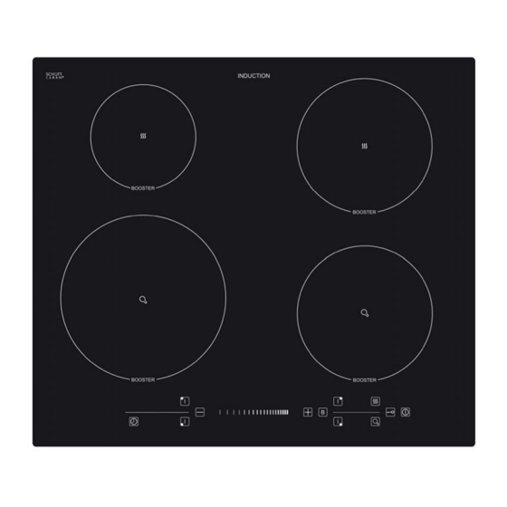
Page 11: Control Panel Layout
Control panel layout 1) Cooking zone selection b uttons 2) ON / OFF pow er button 3) Plus and minus buttons 4) Timer button 5) Power level slider control 6) Boost button 7) Function buttons 8) Safety lock button Using the cera mic hob Before first use... -
Page 12: Switching The Hob On
Switching the hob on o When the hob is connected to the power supply, the buzzer will beep once and all the indicator lights will turn on for about 1 second then switch off again. After this, the hob will enter stand- by mode. -
Page 13: Switching Off A Zone Gradually
MPORTANT: The cooking zone will return to stand-by mode if no operation is carried out with in 1 minute of pressing the ON / FF button. Switching off a zone gradually o Press the cooking zone selection button (1) of the cooking zone that you want to switch off. -
Page 14: Residual Heat Indicator
Residual heat indicator o After a zo ne is switched off, the corresponding cooking zone indicator will show a flashing letter “H”. This means that the temperature of the zone is over 60°C and is therefore still high enough to cause injury. -
Page 15: The Boost Function
o Certain types of cookware may result in a noise being made when being used on an induction zone hob. This do es not mean that there is an appliance fault. IMPORTANT: You should make sure that all pans are placed in th e centre of the induction zone that you are using. -
Page 16: The Warm Function
o The table be low shows the booster power of each zone. Cooking zone MAX power (kW) Normal Boost Front left 2.20 2.90 Rear left 1.50 2.00 Rear right 2.00 2.80 Front right 1.50 2.00 The w rm function his function is designed to automatically keep cooked food warm using variable low power levels. -
Page 17: The Hob Timer
o To turn the fry function off, press the relevant cooking zon selection button (1) followed by the fry function button again (7) and the cooking zone will return to its original power level. o Alternatively, you can press the plus and minus buttons (3) simultaneously, after selectin g the relevant cooking zone, to switch off the fry function, set the power level to “0”... -
Page 18: The Safety Lock
o This timer function can be applied to each burner separately by repeating the steps outlined above after setting the first timer. RNING: It is vital that you do not leave the hob unattended while cooking. our hob also has an alarm mode which is a count-down timer that does not control the heating elements. -
Page 19: Safety Cut-Off
(2) which can still be used to turn the hob off immediately in an emergency. o If the safety lock is activated when the cooking zones are not in use, the tim er indicator will show “Lo” for 1 minute when the hob is turned on. - Page 20 o Before use, make sure that the bottoms of the saucepans are clean and dry. o When cold, the bottom of the pans should be slightly concave, as they expand when hot and lie flat on the surface of the hob. This will allow the heat to transfer more easily.
-
Page 21: Cleaning And Maintenance
Cleaning and maintenance Cleaning operations must only be carried out when the hob is cool. The appliance should be disconnected fro m your mains supply be fore commencing any cleaning process. Clea ing the ceramic hob top Any residues that are left on the hob top surface from cleaning agents will damage it. -
Page 22: Using A Ceramic Hob Scraper
Using a ceramic hob scraper A ceramic hob scraper will be provided with your appliance. The llowing guidelines should be followed when using the ceramic hob craper:- o The scraper should be placed on the ceramic surface at an angle. o Residues should be removed by sliding the blade carefully over the ceramic surface. -
Page 23: Positioning
Position The adjacent furniture must be able to withstand a minimum tempe rature rise of 85°C above the ambient temperature of the room it is located in, during periods of use. This appliance is classified as Class 3 and therefore is to be built into a itchen unit (depending on size) or 600 mm worktop that is 45 mm thick. -
Page 24: Unpacking The Appliance
Unpacking the appliance When unpacking the appliance please check that the following items are contained within the packaging:- 1 Baumatic hob 1 Ceramic hob scraper 1 Installation and instruction manual 1 Warranty card 4 Fixing brackets 4 Fixing screws... -
Page 25: Installing The Appliance
Installing the appliance o Cut a hole in the worktop that corresponds with the drawing shown above. o If the hob is being installed without an oven below it, a separator panel must be placed between the bottom of the hob and the housing below it, at a minimum distance of 10 mm. - Page 26 o IMPORTANT: There ventilation holes around the outside of the hob. YOU MUST ensure that these holes are not blocked by the work top, when you put the hob into position (see drawing opposite). o Carefully turn the hob upside down and place it on a cushioned mat.
-
Page 27: Electrical Connection
o Carefully turn the hob back over and then gently lower it into the aperture hole that you have cut out. o There are holes on the base or the sides of the hob that you can fix the four brackets to. There are three holes in each one of the brackets. -
Page 28: Connecting The Mains Supply Cable
Connecting the mains supply cable o The mains terminal block is located on the underside of the hob and the terminals are accessible by removing the terminal block cover by removing the cover screw. o The brass links must be positioned as marked in the appropriate diagram and once established ALL terminal screws must be tightened down firmly. -
Page 29: My Appliance Isn't Working Correctly
o Open the terminal block on the underside of the hob. o Unscrew the terminal screws fixing the cable. o Replace the cable with one of the same length and in accordance with the specification given on page 27. o The “green-yellow” earth wire must be connected to the terminal marked . -
Page 30: Error Codes
o A humming sound is heard when a cooking zone is selected. * This is normal; the sound will disappear when the zone heats up. o The cooking zones have become discoloured. * This maybe caused by burnt on remnants of food. This will not affect the working of the appliance. -
Page 31: Warranty Card
Or any installation other than the one specified by Baumatic Ltd. has been completed. Please refer to the conditions of guarantee that appear on the... - Page 36 36 36...
Need help?
Do you have a question about the BKF24ID and is the answer not in the manual?
Questions and answers