
Related Manuals for Supero SuperServer 5015M-UR


Summary of Contents for Supero SuperServer 5015M-UR
- Page 1 UPER ® 5015M-UR UPER ERVER 5015M-U UPER ERVER 5015M-NTR UPER ERVER 5015M-NT UPER ERVER USER’S MANUAL 1.0c...
- Page 2 The information in this User’s Manual has been carefully reviewed and is believed to be accurate. The vendor assumes no responsibility for any inaccuracies that may be contained in this document, makes no commitment to update or to keep current the information in this manual, or to notify any person or organization of the updates.
-
Page 3: Preface
Preface About This Manual This manual is written for professional system integrators and PC technicians. It pro- vides information for the installation and use of the SuperServer 5015M-UR/5015M- U/5015M-NTR/5015M-NT. Installation and maintenance should be performed by experienced technicians only. The SuperServer 5015M-UR/5015M-U/5015M-NTR/5015M-NT is a high-end server based on the SC815TQ-R450U/SC815TQ-560U 1U rackmount chassis and the ®... - Page 4 You should thoroughly familiarize yourself with this chapter for a general overview of safety precautions that should be followed when installing and servicing the SuperServer 5015M-UR/5015M-U/5015M-NTR/5015M-NT. Chapter 5: Advanced Serverboard Setup Chapter 5 provides detailed information on the PDSMU serverboard, including the locations and functions of connections, headers and jumpers.
- Page 5 Preface Notes...
-
Page 6: Table Of Contents
UPER ERVER 5015M-UR/5015M-U/5015M-NTR/5015M-NT User's Manual Table of Contents Preface About This Manual ...................... iii Manual Organization ....................iii Chapter 1: Introduction Overview ......................1-1 Serverboard Features ..................1-2 Server Chassis Features ................1-3 Contacting Supermicro ................... 1-6 Chapter 2: Server Installation Overview ...................... - Page 7 Table of Contents Chapter 4: System Safety Electrical Safety Precautions ................4-1 General Safety Precautions ................4-2 ESD Precautions .................... 4-3 Operating Precautions ..................4-4 Chapter 5: Advanced Serverboard Setup Handling the Serverboard ................5-1 Processor and Heatsink Installation ............... 5-2 Connecting Cables ..................
- Page 8 UPER ERVER 5015M-UR/5015M-U/5015M-NTR/5015M-NT User's Manual Wake-On-Ring ..................5-17 Power SMB Connector ................5-17 Power Supply Fail .................. 5-17 Alarm Reset ................... 5-17 LAN 1/2 (Ethernet Ports) ............... 5-18 Power LED ..................... 5-18 Jumper Settings .................... 5-19 Explanation of Jumpers ................. 5-19 CMOS Clear ...................
- Page 9 Table of Contents Advanced Setup ..................... 7-6 Security ......................7-16 Boot ......................7-17 Exit ........................ 7-18 Appendices: Appendix A: BIOS POST Messages Appendix B: BIOS POST Codes Appendix C: Intel HostRAID Appendix D: Adaptec HostRAID Setup Guidelines Appendix E: System Specifi cations...
- Page 10 UPER ERVER 5015M-UR/5015M-U/5015M-NTR/5015M-NT User's Manual Notes...
-
Page 11: Chapter 1: Introduction
Chapter 1: Introduction Chapter 1 Introduction Overview The 5015M-UR/5015M-U/5015M-NTR/5015M-NT is a 1U server comprised of two main subsystems: the SC815TQ-R450U (5015M-UR/5015M-NTR)/SC815TQ-560U (5015M-U/5015M-NT) chassis and the PDSMU single processor serverboard. Please refer to our web site for information on operating systems that have been certifi... -
Page 12: Serverboard Features
Note: a "V" at the end of the server name indicates the chassis is silver, "B" indicates black. Serverboard Features At the heart of the SuperServer 5015M-UR/5015M-U/5015M-NTR/5015M-NT lies the PDSMU, a single processor serverboard based on Intel's 3010 chipset. Below are the main features of the PDSMU (see Figure 1-1 for a block diagram of the chipset). -
Page 13: Server Chassis Features
BIOS rescue. Server Chassis Features The SuperServer 5015M-UR/5015M-U/5015M-NTR/5015M-NT is a high-end, sca- leable server platform built upon the SC815TQ-R450U/SC815TQ-560U 1U server chassis. The following is a general outline of the main features of the SC815TQ- R450U/SC815TQ-560U chassis. - Page 14 UPER ERVER 5015M-UR/5015M-U/5015M-NTR/5015M-NT User's Manual PCI Expansion Slots 5015M-UR/5015M-U: A riser card on the right side of the chassis supports one PCI-E x4 card. The left side supports a UIO card and one PCI-E x8 card. 5015M-NTR/5015M-NT: A riser card on the right side of the chassis supports one PCI-E x4 card.
-
Page 15: System Block Diagram
Chapter 1: Introduction Figure 1-1. Intel 3010 Chipset: System Block Diagram Note: This is a general block diagram. Please see Chapter 5 for details. LGA775_PROCESSOR VRM 11.0 CK410 CLK FSB: 1066/800/533MHz DDR2 DDR2_667/533/400 PCIE_x8 Intel 3010 1x PCIE_x8 CH_A1-2 1PCIE_x16 Slot PCIE_x8 CH_B1-2 1x PCIE_x8... -
Page 16: Contacting Supermicro
UPER ERVER 5015M-UR/5015M-U/5015M-NTR/5015M-NT User's Manual Contacting Supermicro Headquarters Address: Super Micro Computer, Inc. 980 Rock Ave. San Jose, CA 95131 U.S.A. Tel: +1 (408) 503-8000 Fax: +1 (408) 503-8008 Email: marketing@supermicro.com (General Information) support@supermicro.com (Technical Support) Web Site: www.supermicro.com Europe Address: Super Micro Computer B.V. -
Page 17: Chapter 2: Server Installation
Unpacking the System You should inspect the box the SuperServer 5015M-UR/5015M-U/5015M-NTR/ 5015M-NT was shipped in and note if it was damaged in any way. If the server itself shows damage you should fi... -
Page 18: Choosing A Setup Location
UPER ERVER 5015M-UR/5015M-U/5015M-NTR/5015M-NT User's Manual Choosing a Setup Location - Leave enough clearance in front of the rack to enable you to open the front door completely (~25 inches). - Leave approximately 30 inches of clearance in the back of the rack to allow for suffi... -
Page 19: Rack Mounting Considerations
Chapter 2: Server Installation Rack Mounting Considerations Ambient Operating Temperature If installed in a closed or multi-unit rack assembly, the ambient operating tempera- ture of the rack environment may be greater than the ambient temperature of the room. Therefore, consideration should be given to installing the equipment in an environment compatible with the manufacturer’s maximum rated ambient tempera- ture (Tmra). -
Page 20: Installing The System Into A Rack
UPER ERVER 5015M-UR/5015M-U/5015M-NTR/5015M-NT User's Manual Installing the System into a Rack This section provides information on installing the 5015M-UR/5015M-U/5015M- NTR/5015M-NT into a rack unit with the rack rails provided. If the system has already been mounted into a rack, you can skip ahead to Sections 2-5 and 2-6. There are a variety of rack units on the market, which may mean the assembly procedure will differ slightly. -
Page 21: Installing The Outer Rails
Chapter 2: Server Installation Installing the Outer Rails Begin by measuring the distance from the front rail to the rear rail of the rack. Attach a short bracket to the front side of the right outer rail and a long bracket to the rear side of the right outer rail. -
Page 22: Installing The Server Into The Rack
UPER ERVER 5015M-UR/5015M-U/5015M-NTR/5015M-NT User's Manual Installing the Server into the Rack You should now have rails attached to both the chassis and the rack unit. The next step is to install the server into the rack. Do this by lining up the rear of the chas- sis rails with the front of the rack rails. -
Page 23: Installing The Server Into A Telco Rack
Chapter 2: Server Installation Installing the Server into a Telco Rack To install the 5015M-UR/5015M-U/5015M-NTR/5015M-NT into a Telco type rack, use two L-shaped brackets on either side of the chassis (four total). First, determine how far follow the server will extend out the front of the rack. Larger chassis should be positioned to balance the weight between front and back. -
Page 24: Checking The Serverboard Setup
UPER ERVER 5015M-UR/5015M-U/5015M-NTR/5015M-NT User's Manual Checking the Serverboard Setup After you install the 5015M-UR/5015M-U/5015M-NTR/5015M-NT in the rack, you will need to open the top cover to make sure the serverboard is properly installed and all the connections have been made. 1. - Page 25 Chapter 2: Server Installation Figure 2-5. Accessing the Inside of the System...
-
Page 26: Checking The Drive Bay Setup
UPER ERVER 5015M-UR/5015M-U/5015M-NTR/5015M-NT User's Manual Checking the Drive Bay Setup Next, you should check to make sure the peripheral drives and the SATA drives and SATA backplane have been properly installed and all connections have been made. 1. Accessing the drive bays All drives are accessable from the front of the server. -
Page 27: Chapter 3: System Interface
Chapter 3: System Interface Chapter 3 System Interface Overview There are several LEDs on the control panel as well as others on the SATA drive carriers to keep you constantly informed of the overall status of the system as well as the activity and health of specifi... -
Page 28: Control Panel Leds
UPER ERVER 5015M-UR/5015M-U/5015M-NTR/5015M-NT User's Manual Control Panel LEDs The control panel located on the front of th SC815TQ-R450U/SC815TQ-560U chassis has fi ve LEDs. These LEDs provide you with critical information related to different parts of the system. This section explains what each LED indicates when illuminated and any corrective action you may need to take. -
Page 29: Nic2
NIC2: Indicates network activity on LAN2 when fl ashing . NIC1: Indicates network activity on LAN1 when fl ashing. HDD: Indicates IDE channel activity. On the SuperServer 5015M-UR/ 5015M-U/5015M-NTR/5015M-NT this light indicates SATA and/or DVD-ROM drive activity when fl ashing. - Page 30 UPER ERVER 5015M-UR/5015M-U/5015M-NTR/5015M-NT User's Manual Notes...
-
Page 31: Chapter 4: System Safety
Chapter 4: System Safety Chapter 4 System Safety Electrical Safety Precautions Basic electrical safety precautions should be followed to protect yourself from harm and the system from damage: Be aware of the locations of the power on/off switch on the chassis as well as the room's emergency power-off switch, disconnection switch or electrical outlet. -
Page 32: General Safety Precautions
Contact technical support for details and support. General Safety Precautions Follow these rules to ensure general safety: Keep the area around the SuperServer 5015M-UR/5015M-U/5015M-NTR/ 5015M-NT clean and free of clutter. The SuperServer 5015M-UR/5015M-U/5015M-NTR/5015M-NT weighs approximately 45/42 lbs. (20.5/19.1 kg.) when fully loaded. When lifting the system, two people at either end should lift slowly with their feet spread out to distribute the weight. -
Page 33: Esd Precautions
Chapter 4: System Safety After accessing the inside of the system, close the system back up and secure it to the rack unit with the retention screws after ensuring that all connections have been made. ESD Precautions Electrostatic discharge (ESD) is generated by two objects with different electrical charges coming into contact with each other. -
Page 34: Operating Precautions
UPER ERVER 5015M-UR/5015M-U/5015M-NTR/5015M-NT User's Manual Operating Precautions Care must be taken to assure that the chassis cover is in place when the 5015M- UR/5015M-U/5015M-NTR/5015M-NT is operating to ensure proper cooling. Out of warranty damage to the 5015M-UR/5015M-U/5015M-NTR/5015M-NT system can occur if this practice is not strictly followed. Figure 4-1. -
Page 35: Chapter 5: Advanced Serverboard Setup
Chapter 5: Advanced Serverboard Setup Chapter 5 Advanced Serverboard Setup This chapter covers the steps required to install processors and heatsinks to the PDSMU serverboard, connect the data and power cables and install add-on cards. All serverboard jumpers and connections are described and a layout and quick reference chart are included in this chapter. -
Page 36: Processor And Heatsink Installation
UPER ERVER 5015M-UR/5015M-U/5015M-NTR/5015M-NT User's Manual Processor and Heatsink Installation When handling the processor, avoid placing direct pressure on the label area of the fan. Also, do not place the serverboard on a conductive surface, which can damage the BIOS battery and prevent the system from booting up. - Page 37 Chapter 5: Advanced Serverboard Setup 3. Use your thumb and your index fi nger to hold the CPU at opposite sides. 4. Align pin1 of the CPU (the corner marked with a triangle) with the notched corner of the CPU socket. 5.
- Page 38 UPER ERVER 5015M-UR/5015M-U/5015M-NTR/5015M-NT User's Manual Installing the Heatsink 1. Do not apply any thermal grease to the heatsink or the CPU die; the required amount has already been applied. 2. Place the heatsink on top of the CPU so that the four mounting holes are aligned with those on the (preinstalled) heatsink retention mechanism.
-
Page 39: Connecting Cables
Chapter 5: Advanced Serverboard Setup Connecting Cables Now that the processors are installed, the next step is to connect the cables to the serverboard. These include the data (ribbon) cables for the peripherals and control panel and the power cables. Connecting Data Cables The ribbon cables used to transfer data from the peripheral devices have been carefully routed in preconfi... -
Page 40: Connecting The Control Panel
UPER ERVER 5015M-UR/5015M-U/5015M-NTR/5015M-NT User's Manual Connecting the Control Panel JF1 contains header pins for various front control panel connectors. See Figure 5-1 for the pin locations of the various front control panel buttons and LED indi- cators. Please note that even and odd numbered pins are on opposite sides of each header. -
Page 41: I/O Ports
Chapter 5: Advanced Serverboard Setup I/O Ports The I/O ports are color coded in conformance with the PC 99 specifi cation. See Figure 5-2 below for the colors and locations of the various I/O ports. Figure 5-2. Rear Panel I/O Ports Mouse (Green) COM1 Port... - Page 42 UPER ERVER 5015M-UR/5015M-U/5015M-NTR/5015M-NT User's Manual Memory Support The PDSMU supports up to 8 GB of unbuffered ECC/non-ECC DDR2-667/533/400 SDRAM. Interleaved memory requires modules of the same size and speed to be installed in pairs. Do not mix DIMMs of different sizes and speeds. Notes: Due to OS limitations, some operating systems may not show more than 4 GB of memory.
-
Page 43: Adding Pci Cards
Chapter 5: Advanced Serverboard Setup Adding PCI Cards 1. PCI Expansion Slots Two riser cards are used to support add-on cards to the system. The SC815TQ- R450U/SC815TQ-560U chassis can accommodate one standard size (full height full length) and one low profi le PCI expansion card. When viewed from the chassis front, the standard size card installs to the left and the low-profi... -
Page 44: Serverboard Details
UPER ERVER 5015M-UR/5015M-U/5015M-NTR/5015M-NT User's Manual Serverboard Details Figure 5-4. SUPER PDSMU Layout (not drawn to scale) COM1 USB0/1 Mouse LAN2 LAN1 JWOR Speaker Battery JPL1 BIOS USB4/5 JPL2 JBT1 JPG1 ES1000 ICH7R USB2/3 SATA0 South Bridge SATA1 SATA2 SATA3 Intel 3010 North Bridge JLED LGA 775... -
Page 45: Pdsmu Quick Reference
Chapter 5: Advanced Serverboard Setup PDSMU Quick Reference Jumper Description Default Setting Alarm Reset Enable Open (Disabled) JBT1 CMOS Clear See Section 5-9 Power Force-On Open (Disabled) JPG1 VGA Enable Pins 1-2 (Enabled) JPL1/JPL2 Giga-bit LAN 1/2 Enable Pins 1-2 (Enabled) Watch Dog Enable Pins 1-2 (Reset) Connector... -
Page 46: Connector Defi Nitions
UPER ERVER 5015M-UR/5015M-U/5015M-NTR/5015M-NT User's Manual Connector Defi nitions ATX Power 24-pin Connector Pin Defi nitions (JPW1) Pin# Defi nition Pin # Defi nition ATX Power Connector +3.3V +3.3V The primary ATX power supply con- -12V +3.3V nector meets the SSI (Superset ATX) 24-pin specifi... -
Page 47: Hdd Led
Chapter 5: Advanced Serverboard Setup HDD LED HDD LED Pin Defi nitions (JF1) The HDD (IDE Hard Disk Drive) LED Pin# Defi nition connection is located on pins 13 and 14 of JF1. Attach the IDE hard drive HD Active LED cable to display disk activity. -
Page 48: Power Fail Led
UPER ERVER 5015M-UR/5015M-U/5015M-NTR/5015M-NT User's Manual Power Fail LED Power Fail LED Pin Defi nitions (JF1) The Power Fail LED connection is Pin# Defi nition located on pins 5 and 6 of JF1. Re- fer to the table on the right for pin Ground defi... -
Page 49: Universal Serial Bus Headers
Chapter 5: Advanced Serverboard Setup Universal Serial Bus Universal Serial Bus Headers Pin Defi nitions (USB2/3, USB4/5) Headers USB2 USB3, USB4 Pin # Defi nition Pin # Defi nition Four additional USB headers (USB2/3 and USB4/5) are included on the serverboard. -
Page 50: Chassis Intrusion
UPER ERVER 5015M-UR/5015M-U/5015M-NTR/5015M-NT User's Manual Chassis Intrusion Chassis Intrusion Pin Defi nitions (JL1) A Chassis Intrusion header is located Pin# Defi nition at JL1. Attach the appropriate cable Intrusion Input to inform you of a chassis intrusion. Ground Speaker Connector Speaker Connector Pin Defi... -
Page 51: Wake-On-Ring
Chapter 5: Advanced Serverboard Setup Wake-On-Ring Wake-On-Ring Pin Defi nitions (JWOR) The Wake-On-Ring header is desig- Pin# Defi nition nated JWOR. This function allows Ground (Black) your computer to receive and "wake- Wake-up up" by an incoming call to the modem when in suspend state. -
Page 52: Lan1/2 (Ethernet Ports)
UPER ERVER 5015M-UR/5015M-U/5015M-NTR/5015M-NT User's Manual LAN1/2 (Ethernet Ports) Two Ethernet ports (designated LAN1 and LAN2) are located beside the VGA port on the I/O backplane. These ports accept RJ45 type cables. Power LED Power LED Pin Defi nitions (JLED) The Power LED connector is desig- Pin# Defi... -
Page 53: Jumper Settings
Chapter 5: Advanced Serverboard Setup Jumper Settings Explanation of Jumpers To modi f y the operat ion of the Connector Pins serverboard, jumpers can be used to choose between optional settings. Jumpers create shorts between two Jumper pins to change the function of the connector. -
Page 54: Lan Enable/Disable
UPER ERVER 5015M-UR/5015M-U/5015M-NTR/5015M-NT User's Manual LAN Enable/Disable LAN Enable/Disable Jumper Settings (JPL1, JPL2) Change the setting of jumper JPL1 Jumper Setting Defi nition or JPL2 to enable or disable the Pins 1-2 Enabled onboard Ethernet (RJ45) ports LAN1 Pins 2-3 Disabled and LAN2, respectively. -
Page 55: 5-10 Onboard Indicators
Chapter 5: Advanced Serverboard Setup 5-10 Onboard Indicators LAN LED Connection Speed Indicator LAN1/LAN2 LEDs LED Color Defi nition The Ethernet ports (located beside the 10 MHz VGA port) have two LEDs. On each Green 100 MHz Gigabit LAN port, one LED indicates Amber 1 GHz activity when blinking while the other... -
Page 56: 5-11 Floppy, Ide And Sata Drive Connections
UPER ERVER 5015M-UR/5015M-U/5015M-NTR/5015M-NT User's Manual 5-11 Floppy, IDE and SATA Drive Connections Note the following when connecting the fl oppy and hard disk drive cables: • The fl oppy disk drive cable has seven twisted wires. • A red mark on a wire typically designates the location of pin 1. •... -
Page 57: Ide Connector
Chapter 5: Advanced Serverboard Setup IDE Connector IDE Drive Connector Pin Defi nitions (IDE#1) Pin# Defi nition Pin # Defi nition There are no jumpers to con- Reset IDE Ground fi gure the onboard IDE#1 con- Host Data 7 Host Data 8 nector. - Page 58 UPER ERVER 5015M-UR/5015M-U/5015M-NTR/5015M-NT User's Manual Notes 5-24...
-
Page 59: Chapter 6: Advanced Chassis Setup
Chapter 6: Advanced Chassis Setup Chapter 6 Advanced Chassis Setup This chapter covers the steps required to install components and perform mainte- nance on the SC815TQ-R450U/SC815TQ-560U chassis. For component installa- tion, follow the steps in the order given to eliminate the most common problems encountered. -
Page 60: Control Panel
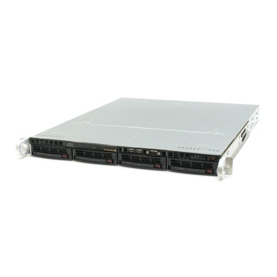
UPER ERVER 5015M-UR/5015M-U/5015M-NTR/5015M-NT User's Manual Figure 6-1. Chassis: Front and Rear Views Slim DVD-ROM Drive Slim Floppy Drive (optional) System LEDs Control Panel SATA Drive Bays System Reset Main Power Power Supply Module USB Ports PCI Expansion Slots (w/ riser cards) Mouse/Keyboard COM1 Port VGA Port... -
Page 61: System Fans
Chapter 6: Advanced Chassis Setup System Fans Three 4-cm heavy duty counter-rotating fans provide the cooling for the SuperServer 5015M-UR/5015M-U/5015M-NTR/5015M-NT. Each fan unit is actually made up of two fans joined back-to-back, which rotate in opposite directions. This counter- rotating action generates exceptional airfl ow and works to dampen vibration levels. It is very important that the chassis top cover is properly installed and making a good seal in order for the cooling air to circulate properly through the chassis and cool the components. -
Page 62: Drive Bay Installation/Removal
UPER ERVER 5015M-UR/5015M-U/5015M-NTR/5015M-NT User's Manual Figure 6-2. System Cooling Fans Note: redundant power supply shown applies to 5015M-UR and 5015M-NTR only. Drive Bay Installation/Removal Removing the Front Bezel If your system has a front bezel (optional) attached to the chassis, you must fi rst remove it to gain access to the drive bays. -
Page 63: Accessing The Drive Bays
Chapter 6: Advanced Chassis Setup Figure 6-3. Removing the Front Bezel 1. Unlock 2. Press release knob 3. Remove bezel assembly Accessing the Drive Bays SATA Drives: Because of their hotswap capability, you do not need to access the inside of the chassis or power down the system to install or replace SATA drives. Proceed to the next section for instructions. -
Page 64: Sata Drive Installation
UPER ERVER 5015M-UR/5015M-U/5015M-NTR/5015M-NT User's Manual SATA Drive Installation 1. Mounting a SATA drive in a drive carrier The SATA drives are mounted in drive carriers to simplify their installation and removal from the chassis. These carriers also help promote proper airfl ow for the drive bays. - Page 65 Chapter 6: Advanced Chassis Setup 2. Installing/removing hot-swap SATA drives The SATA drive carriers are all easily accessible at the front of the chassis. These hard drives are hot-pluggable, meaning they can be removed and installed without powering down the system. To remove a carrier, push the release button located beside the drive LEDs.
- Page 66 UPER ERVER 5015M-UR/5015M-U/5015M-NTR/5015M-NT User's Manual DVD-ROM and Floppy Drive Installation The top cover of the chassis must be opened to gain full access to the DVD-ROM and fl oppy drive bays. The 5015M-UR/5015M-U/5015M-NTR/5015M-NT acco- modates only slim-line DVD-ROM drives. Side mounting brackets are needed to mount a slim-line DVD-ROM drive in the 5015M-UR/5015M-U/5015M-NTR/5015M- NT server.
-
Page 67: Power Supply
Chapter 6: Advanced Chassis Setup Power Supply 5015M-UR/5015M-NTR The SuperServer 5015M-UR/5015M-NTR has a 450 watt redundant power supply confi guration consisting of two hot-swap power modules. The power supply mod- ules have an auto-switching capability, which enables them to automatically sense and operate with a 100V - 240V input voltage. -
Page 68: Power Supply Failure
UPER ERVER 5015M-UR/5015M-U/5015M-NTR/5015M-NT User's Manual 5015M-U/5015M-NT The SuperServer 5015M-U/5015M-NT has a single 560 watt power supply, which is auto-switching capable. This enables it to automatically sense and operate with a 100v - 240v input voltage. Power Supply Failure If the power supply module fails, the system will shut down and you will need to replace the module. - Page 69 Chapter 6: Advanced Chassis Setup Figure 6-6. Removing/Replacing the Power Supply Note: redundant power supply shown applies to 5015M-UR and 5015M-NTR only. 6-11...
- Page 70 UPER ERVER 5015M-UR/5015M-U/5015M-NTR/5015M-NT User's Manual Notes 6-12...
-
Page 71: Chapter 7: Bios
Chapter 7: BIOS Chapter 7 BIOS Introduction This chapter describes the Phoenix BIOS™ Setup utility for the PDSMU. The Phoenix ROM BIOS is stored in a fl ash chip and can be easily upgraded using a fl oppy disk-based program. Note: Due to periodic changes to the BIOS, some settings may have been added or deleted and might not yet be recorded in this manual. -
Page 72: Running Setup
UPER ERVER 5015M-UR/5015M-U/5015M-NTR/5015M-NT User's Manual Running Setup Default settings are in bold text unless otherwise noted. The BIOS setup options described in this section are selected by choosing the appropriate text from the main BIOS Setup screen. All displayed text is described in this section, although the screen display is often all you need to understand how to set the options (See the next page). -
Page 73: Main Setup Features
Chapter 7: BIOS Main BIOS Setup Menu Main Setup Features System Time To set the system date and time, key in the correct information in the appropriate fi elds. Then press the <Enter> key to save the data. System Date Using the arrow keys, highlight the month, day and year fi... - Page 74 UPER ERVER 5015M-UR/5015M-U/5015M-NTR/5015M-NT User's Manual Serial ATA This setting allows the user to enable or disable the function of Serial ATA. The options are Disabled and Enabled. Native Mode Operation Select the native mode for ATA. The options are Serial ATA and Auto. SATA Controller Mode Select Compatible to allow the SATA and PATA drives to be automatically- detected and be placed in the Legacy Mode by the BIOS.
- Page 75 Chapter 7: BIOS Type Selects the type of IDE hard drive. The option Auto will allow the BIOS to automatically confi gure the parameters of the HDD installed at the connection. Enter a number between 1 to 39 to select a predetermined HDD type. Select User to allow the user to enter the parameters of the HDD installed.
-
Page 76: Advanced Setup
UPER ERVER 5015M-UR/5015M-U/5015M-NTR/5015M-NT User's Manual Advanced Setup Choose Advanced from the Phoenix BIOS Setup Utility main menu with the arrow keys. You should see the following display. The items with a triangle beside them have sub menus that can be accessed by highlighting the item and pressing <Enter>. Boot Features Access the submenu to make changes to the following settings. - Page 77 Chapter 7: BIOS Resume On Modem Ring Select On to “wake your system up” when an incoming call is received by your modem. The options are On and Off. Resume On PME# Select On to allow your system be woken up when signals are received by the selected PME# of a PCI slot.
- Page 78 UPER ERVER 5015M-UR/5015M-U/5015M-NTR/5015M-NT User's Manual Select Write Protect to prevent data from being written into the base memory area of Block 0-512K. Select Write Back to allow the CPU to write data back directly from the buffer without writing data to the System Memory for fast CPU data processing and operation.
- Page 79 Chapter 7: BIOS Slot1 PCI-Exp. x8, Slot2 PCI-Exp. x8 and Slot3 PCI-Exp. x4 Access the submenu for each of the settings above to make changes to the following: Option ROM Scan When enabled, this setting will initialize the device expansion ROM. The options are Enabled and Disabled.
- Page 80 UPER ERVER 5015M-UR/5015M-U/5015M-NTR/5015M-NT User's Manual USB Function Select Enabled to activate the USB devices specifi ed. The settings are Enabled and Disabled. Legacy USB Support This setting allows you to enable support for Legacy USB devices. The settings are Enabled and Disabled. Advanced Processor Options Access the submenu to make changes to the following settings.
- Page 81 Chapter 7: BIOS Adjacent Cache Line Prefetch (Available when supported by the CPU.) The CPU fetches the cache line for 64 bytes if this option is set to Disabled. The CPU fetches both cache lines for 128 bytes as comprised if Enabled. The default settings are Disabled for the Intel 5100 Series Processors and Enable for the 5000 Series Processors.
- Page 82 UPER ERVER 5015M-UR/5015M-U/5015M-NTR/5015M-NT User's Manual Serial Port A This setting allows you to assign control of serial port A. The options are Enabled (user defi ned), Disabled, and Auto (BIOS- or OS- controlled). Base I/O Address This setting allows you to select the base I/O address for serial port A. The options are 3F8, 2F8, 3E8, and 2E8.
- Page 83 Chapter 7: BIOS DMI Event Logging Access the submenu to make changes to the following settings. Event Log Validity This is a display to inform you of the event log validity. It is not a setting. Event Log Capacity This is a display to inform you of the event log capacity. It is not a setting. View DMI Event Log Highlight this item and press <Enter>...
- Page 84 UPER ERVER 5015M-UR/5015M-U/5015M-NTR/5015M-NT User's Manual Console Redirection Access the submenu to make changes to the following settings. COM Port Address This item allows you to specify which COM port to direct the remote console to: Onboard COM A or Onboard COM B. This setting can also be Disabled. BAUD Rate This item allows you to set the BAUD rate for console redirection.
-
Page 85: Hardware Monitor Logic
Chapter 7: BIOS Hardware Monitor Logic Note: The Phoenix BIOS will automatically detect the type of CPU(s) and hardware monitoring chip used on the motherboard and will display the Hardware Monitoring screen accordingly. CPU Temperature Threshold This option allows the user to set a CPU temperature threshold that will activate the alarm system when the CPU temperature reaches this pre-set temperature threshold. -
Page 86: Security
UPER ERVER 5015M-UR/5015M-U/5015M-NTR/5015M-NT User's Manual Security Choose Security from the Phoenix BIOS Setup Utility main menu with the arrow keys. You should see the following display. Security setting options are displayed by highlighting the setting using the arrow keys and pressing <Enter>. All Security BIOS settings are described in this section. -
Page 87: Boot
Chapter 7: BIOS Password on Boot This setting allows you to decide if a password is required for a user to access the system at the boot-up. The options are Enabled (password required) and Disabled (password not required). Boot Choose Boot from the Phoenix BIOS Setup Utility main menu with the arrow keys. You should see the following display. -
Page 88: Exit
UPER ERVER 5015M-UR/5015M-U/5015M-NTR/5015M-NT User's Manual Exit Choose Exit from the Phoenix BIOS Setup Utility main menu with the arrow keys. You should see the following display. All Exit BIOS settings are described in this section. Exit Saving Changes Highlight this item and press <Enter> to save any changes you've made and to exit the BIOS Setup utility. -
Page 89: Appendix A: Bios Post Messages
Appendix A: BIOS POST Messages Appendix A BIOS POST Messages During the Power-On Self-Test (POST), the BIOS will check for problems. If a prob- lem is found, the BIOS will activate an alarm or display a message. The following is a list of such BIOS messages. - Page 90 UPER ERVER 5015M-UR/5015M-U/5015M-NTR/5015M-NT User's Manual System CMOS checksum bad - Default confi guration used System CMOS has been corrupted or modifi ed incorrectly, perhaps by an application program that changes data stored in CMOS. The BIOS installed Default Setup Values. If you do not want these values, enter Setup and enter your own values.
- Page 91 Appendix A: BIOS POST Messages System cache error - Cache disabled RAM cache failed and BIOS disabled the cache. On older boards, check the cache jumpers. You may have to replace the cache. See your dealer. A disabled cache slows system performance considerably.
- Page 92 UPER ERVER 5015M-UR/5015M-U/5015M-NTR/5015M-NT User's Manual Invalid System Confi guration Data Problem with NVRAM (CMOS) data. I/O device IRQ confl ict I/O device IRQ confl ict error. PS/2 Mouse Boot Summary Screen: PS/2 Mouse installed. nnnn kB Extended RAM Passed Where nnnn is the amount of RAM in kilobytes successfully tested. nnnn Cache SRAM Passed Where nnnn is the amount of system cache in kilobytes successfully tested.
- Page 93 Appendix A: BIOS POST Messages Press <F1> to resume, <F2> to Setup, <F3> for previous Displayed after any recoverable error message. Press <F1> to start the boot process or <F2> to enter Setup and change the settings. Press <F3> to display the previous screen (usually an initialization error of an Option ROM, i.e., an add-on card).
- Page 94 UPER ERVER 5015M-UR/5015M-U/5015M-NTR/5015M-NT User's Manual Notes...
-
Page 95: Appendix B: Bios Post Codes
Appendix B: BIOS POST Codes Appendix B BIOS POST Codes This section lists the POST (Power On Self Test) codes for the Phoenix BIOS. POST codes are divided into two categories: recoverable and terminal. Recoverable POST Errors When a recoverable type of error occurs during POST, the BIOS will display an POST code that describes the problem. - Page 96 UPER ERVER 5015M-UR/5015M-U/5015M-NTR/5015M-NT User's Manual POST Code Description 8254 timer initialization 8237 DMA controller initialization Reset Programmable Interrupt Controller 1-3-1-1 Test DRAM refresh 1-3-1-3 Test 8742 Keyboard Controller Set ES segment register to 4 GB Auto size DRAM Initialize POST Memory Manager Clear 512 kB base RAM 1-3-4-1 RAM failure on address line xxxx* 1-3-4-3 RAM failure on data bits xxxx* of low byte of...
- Page 97 Appendix B: BIOS POST Codes POST Code Description Test RAM between 512 and 640 kB Test extended memory Test extended memory address lines Jump to UserPatch1 Confi gure advanced cache registers Initialize Multi Processor APIC Enable external and CPU caches Setup System Management Mode (SMM) area Display external L2 cache size Load custom defaults (optional)
- Page 98 UPER ERVER 5015M-UR/5015M-U/5015M-NTR/5015M-NT User's Manual POST Code Description Check for SMART Drive (optional) Set up Power Management Initialize security engine (optional) Enable hardware interrupts Determine number of ATA and SCSI drives Set time of day Check key lock Initialize typematic rate Erase <ESC>...
- Page 99 Appendix B: BIOS POST Codes POST Code Description Unknown interrupt Check Intel Branding string Alert Standard Format initialization Late init for IPMI Log error if micro-code not updated properly The following are for boot block in Flash ROM POST Code Description Initialize the chipset Initialize the bridge Initialize the CPU...
- Page 100 UPER ERVER 5015M-UR/5015M-U/5015M-NTR/5015M-NT User's Manual Notes...
-
Page 101: Appendix C: Intel Hostraid
Appendix C: Intel HostRAID Appendix C Intel HostRAID After the hardware has been installed, you must fi rst confi gure Intel's ICH7R SATA RAID before you install Windows and software drivers. Important Notes to the User Note: If you do not wish to confi gure onboard SATA RAID functions, please go directly to Section C-2 for Operating System &... - Page 102 UPER ERVER 5015M-UR/5015M-U/5015M-NTR/5015M-NT User's Manual RAID Confi gurations The following types of RAID confi gurations are supported: RAID 0 (Data Striping): this writes data in parallel, interleaved ("striped") sections of two hard drives. Data transfer rate is doubled over using a single disk. RAID1 (Data Mirroring): an identical data image from one drive is copied to another drive.
- Page 103 Appendix C: Intel HostRAID Using the Intel ICH7R SATA RAID Utility Program 1. Creating, Deleting and Resetting RAID Volumes a. After the system exits from the BIOS Setup Utility, the system will automatically reboot. The following screen appears after Power-On Self Test. b.
- Page 104 UPER ERVER 5015M-UR/5015M-U/5015M-NTR/5015M-NT User's Manual Creating a RAID 0 Volume a. Select "Create RAID Volume" from the main menu and press the <Enter> key. The following screen will appear: b. Specify a name for the RAID 0 set and press the <Tab> key or the <Enter> key to go to the next fi...
- Page 105 Appendix C: Intel HostRAID Creating a RAID 1 Volume a. Select "Create RAID Volume" from the main menu and press the <Enter> key. The following screen will appear: b. Specify a name for the RAID 1 set and press the <Tab> key or the <Enter> key to go to the next fi...
- Page 106 UPER ERVER 5015M-UR/5015M-U/5015M-NTR/5015M-NT User's Manual Creating a RAID 10 (RAID 1+ RAID 0) a. Select "Create RAID Volume" from the main menu and press the <Enter> key. The following screen will appear: b. Specify a name for the RAID 10 set and press <Enter>. c.
- Page 107 Appendix C: Intel HostRAID Creating a RAID 5 Set (Parity) a. Select "Create RAID Volume" from the main menu and press the <Enter> key. The following screen will appear: b. Specify a name for the RAID 5 set and press <Enter>. c.
- Page 108 UPER ERVER 5015M-UR/5015M-U/5015M-NTR/5015M-NT User's Manual Deleting a RAID Volume Warning: Be sure to back up your data before deleting a RAID set. You will lose all data on the disk drives when deleting a RAID set. a. From the main menu, select item2-Delete RAID Volume, and press <Enter>. b.
- Page 109 Appendix C: Intel HostRAID Resetting to Non-RAID and Resetting a RAID HDD Warning: Be cautious when you reset a RAID volume HDD to non-RAID or Resetting a RAID HDD. Resetting a RAID volume HDD or Resetting a RAID HDD will reformat the HDD and delete all internal RAID confi gura- tions on the drive.
- Page 110 UPER ERVER 5015M-UR/5015M-U/5015M-NTR/5015M-NT User's Manual C-2 Installing Windows XP/2000/2003 for RAID Systems New Operating System-Windows XP/2000/2003 Installation a. Insert Microsoft Windows XP/2000/2003 Setup CD in the CD Driver, and the system will start booting up from CD. b. Press the <F6> key when the message-" Press F6 if you need to install a third party SCSI or RAID driver"...
-
Page 111: Appendix D: Adaptec Hostraid Setup Guidelines
Appendix D: Adaptec HostRAID Setup Guidelines Appendix D Adaptec HostRAID Setup Guidelines After all the hardware has been installed, you must fi rst confi gure the Adaptec Embedded SATA RAID before you install the Windows operating system. The necessary drivers are all included on the Super Micro bootable CDs that came packaged with your serverboard. - Page 112 UPER ERVER 5015M-UR/5015M-U/5015M-NTR/5015M-NT User's Manual Confi guring the Adaptec SATA RAID 1. Press the <Del> key during system bootup to enter the BIOS Setup Utility. Note: If this is the fi rst time you power on the system, we recommend that you load the Optimized Default Settings.
- Page 113 Appendix D: Adaptec HostRAID Setup Guidelines Adaptec Embedded SATA with HostRAID Controller Driver The Adaptec Embedded Serial ATA RAID controller adds SATA/RAID functionality and performance enhancements to a motherboard. RAID striping (RAID 0) allows data to be written across multiple drives, greatly improving hard disk I/O perfor- mance.
- Page 114 UPER ERVER 5015M-UR/5015M-U/5015M-NTR/5015M-NT User's Manual Managing Arrays Select this option to view array properties, and confi gure array settings. To select this option, using the arrow keys and the <enter> key, select "Managing Arrays" from the main menu as shown above.
- Page 115 Appendix D: Adaptec HostRAID Setup Guidelines Confi guring Disk Drives You may need to confi gure a disk drive before you can use it. Caution: Confi guring a disk may overwrite the partition table on the disk and may make any data on the disk inaccessible. If the drive is used in an array, you may not be able to use the array again.
- Page 116 UPER ERVER 5015M-UR/5015M-U/5015M-NTR/5015M-NT User's Manual 2. From the "Select Drives for Confi guring" List (shown below,) select the drives you want to confi gure and press <Insert>. 3. The drive you've selected will appear in the "Selected Drives Dialog Box" on the right (as shown below.) Repeat the same steps until all drives that you want to confi...
- Page 117 Appendix D: Adaptec HostRAID Setup Guidelines 5. Read the warning message as shown in the screen below. 6. Make sure that you have selected the correct disk drives to confi gure. If correct, type Y to continue.
- Page 118 UPER ERVER 5015M-UR/5015M-U/5015M-NTR/5015M-NT User's Manual Creating Arrays Before you create arrays, make sure that the disks for the array are connected and installed in your system. Note that disks with no usable space, or disks that are un-initialized or not formatted are shown in gray and cannot be used. Note: It is recommended that you confi...
- Page 119 Appendix D: Adaptec HostRAID Setup Guidelines Assigning Array Properties Once a new array is completed, you can assign properties to the array. Caution: Once the array is created and its properties are assigned, you cannot change the array properties using this utility. To assign properties to the new array 1.
- Page 120 UPER ERVER 5015M-UR/5015M-U/5015M-NTR/5015M-NT User's Manual 5. When you are fi nished, press <Done> (as the screen shown below). Notes 1. Before adding a new drive to an array, be sure to back up any data stored on the new drive; otherwise, all data will be lost. 2.
- Page 121 Appendix D: Adaptec HostRAID Setup Guidelines Adding a Bootable Array To make an array bootable: 1. From the Main menu, select Manage Arrays. 2. From the List of Arrays, select the array you want to make bootable, and press <Ctrl> and <B>. 3.
- Page 122 UPER ERVER 5015M-UR/5015M-U/5015M-NTR/5015M-NT User's Manual Adding/Deleting Hotspares To add a hotspare: Note: In order to rebuild a RAID (RAID 0 or RAID 1), you would need to add a new HDD as a hotspare. 1. From the main menu (shown on Page D-4), select Add/Delete Hotspares. 2.
- Page 123 Appendix D: Adaptec HostRAID Setup Guidelines Viewing Array Properties To view the properties of an existing array: 1. From the main menu, select Manage Arrays and hit <Enter> (as shown on the previous page.) 2. From the List of Arrays dialog box (shown below), select the array you want to view and press Enter.
- Page 124 UPER ERVER 5015M-UR/5015M-U/5015M-NTR/5015M-NT User's Manual Rebuilding Arrays Notes: Rebuilding applies to Fault Tolerant arrays (RAID 1) only. If an array build process is interrupted or when one critical member is missing, you must perform a Rebuild to restore its functionality. For a critical array rebuild operation, the optimal drive is the source drive.
- Page 125 Appendix D: Adaptec HostRAID Setup Guidelines Deleting Arrays Warning: Back up the data on an array before you delete it to prevent data loss Deleted arrays cannot be restored. To delete an existing array: 1. From the main menu (shown on Page D-4), select Manage Arrays. 2.
-
Page 126: Using The Disk Utilities
UPER ERVER 5015M-UR/5015M-U/5015M-NTR/5015M-NT User's Manual Using the Disk Utilities The Disk Utilities enable you to format or verify the media of your Serial ATA hard disks. To access the disk utilities 1. From the Adaptec RAID Confi guration Utility Menu, select Disk Utilities (as shown above) and press <Enter>. - Page 127 Appendix D: Adaptec HostRAID Setup Guidelines To format a disk Note: The Formatting Disk operation allows you to perform a low-level formatting of a hard drive by writing zeros to the entire disk. Serial ATA drives are low-level formatted at the factory and do not need to be low-level formatted again. 1.
- Page 128 UPER ERVER 5015M-UR/5015M-U/5015M-NTR/5015M-NT User's Manual To verify disk media 1. When the screen shown above displays, select Verify Disk Media and press <Enter>. 2. A message will display, indicating that the selected drive will be scanned for me- dia defects. Select Yes and hit <Enter> to proceed with disk verifying; otherwise, select No and hit <Enter>.
- Page 129 Appendix D: Adaptec HostRAID Setup Guidelines To Exit the Adaptec RAID Confi guration Utility 1. Once you have completed RAID array confi gurations, press ESC to exit. The following screen will appear. 2. Press Yes to exit the Utility. D-19...
- Page 130 UPER ERVER 5015M-UR/5015M-U/5015M-NTR/5015M-NT User's Manual D-2 Installing the Adaptec ICH7R Driver and the OS 1. Insert Supermicro's bootable CD that came with the package into the CD Drive during the system reboot, and the screen: "Super Micro Driver Diskette Maker" will appear.
-
Page 131: Appendix E: System Specifi Cations
Appendix E: System Specifi cations Appendix E System Specifi cations Processors Single 775-pin Intel ® Xeon® 3000 Series, Pentium® D, Pentium Extreme Edition, Pentium 4, and Celeron D processors at a FSB speed of 1066/667/533 MHz Note: Please refer to our web site for a complete listing of supported processors. Chipset Intel 3010 chipset BIOS... - Page 132 UPER ERVER 5015M-UR/5015M-NT User's Manual Serverboard PDSMU (Extended ATX form factor) Dimensions: 12 x 13.05 in (305 x 331 mm) Chassis 5015M-UR/5015M-NTR: SC815TQ-R450U Form Factor: 1U rackmount 5015M-U/5015M-NT: SC815TQ-560U Form Factor: 1U rackmount Dimensions: (WxHxD) 17 x 1.7 x 25.6 in. (432 x 43 x 650 mm) Weight Gross (Bare Bone): 45/42 lbs.
- Page 133 Appendix E: System Specifi cations Operating Environment Operating Temperature: 10º to 35º C (50º to 95º F) Non-operating Temperature: -40º to 70º C (-40º to 158º F) Operating Relative Humidity: 8% to 90% (non-condensing) Non-operating Relative Humidity: 5 to 95% (non-condensing) Regulatory Compliance Electromagnetic Emissions: FCC Class A, EN 55022 Class A, EN 61000-3-2/-3-3, CISPR 22 Class A...
- Page 134 UPER ERVER 5015M-UR/5015M-NT User's Manual Notes...
Need help?
Do you have a question about the SuperServer 5015M-UR and is the answer not in the manual?
Questions and answers