
Related Manuals for Supero SUPERSERVER 5015M-MT


Summary of Contents for Supero SUPERSERVER 5015M-MT
- Page 1 UPER ® 5015M-MT UPER ERVER 5015M-MT+ UPER ERVER USER’S MANUAL Revision 1.0b...
- Page 2 The information in this User’s Manual has been carefully reviewed and is believed to be accurate. The vendor assumes no responsibility for any inaccuracies that may be contained in this document, makes no commitment to update or to keep current the information in this manual, or to notify any person or organization of the updates.
-
Page 3: Preface
Preface About This Manual This manual is written for professional system integrators and PC technicians. It provides information for the installation and use of the SuperServer 5015M-MT/ 5015M-MT+. Installation and maintainance should be performed by experienced technicians only. The SuperServer 5015M-MT/5015M-MT+ is a high-end single processor mini 1U rackmount server based on the SC813MFT-300C 1U rackmount server chassis and the Super PDSMi/PDSMi+ motherboard. - Page 4 You should thoroughly familiarize yourself with this chapter for a general overview of safety precautions that should be followed when installing and servicing the SuperServer 5015M-MT/5015M-MT+. Chapter 5: Advanced Motherboard Setup Chapter 5 provides detailed information on the PDSMi/PDSMi+ motherboard, including the locations and functions of connectors, headers and jumpers.
- Page 5 Preface Notes...
-
Page 6: Table Of Contents
UPER ERVER 5015M-MT/5015M-MT+ User's Manual Table of Contents Preface About This Manual ...................... iii Manual Organization ....................iii Chapter 1: Introduction Overview ......................1-1 Motherboard Features ..................1-2 Server Chassis Features ................1-5 Contacting Supermicro ................... 1-6 Chapter 2: Server Installation Overview ...................... - Page 7 Table of Contents Power ...................... 3-3 Serial ATA Drive Carrier LED ................. 3-3 Chapter 4: System Safety Electrical Safety Precautions ................4-1 General Safety Precautions ................4-2 ESD Precautions .................... 4-3 Operating Precautions ..................4-4 Chapter 5: Advanced Motherboard Setup Handling the Motherboard ................
- Page 8 UPER ERVER 5015M-MT/5015M-MT+ User's Manual JLAN1/2 (Ethernet Ports) ................ 5-15 Serial Ports ..................... 5-16 Power LED ..................... 5-16 Universal Serial Bus ................5-16 5-10 Jumper Settings ..................... 5-17 Explanation of Jumpers ................5-17 CMOS Clear .................... 5-17 Speaker Connector ................5-17 JLAN1 Enable/Disable ................
- Page 9 Table of Contents Chapter 7: BIOS Introduction ...................... 7-1 Running Setup ....................7-2 Main BIOS Setup .................... 7-2 Advanced Setup ..................... 7-7 Security ......................7-19 Boot ......................7-20 Exit ........................ 7-21 Appendices: Appendix A: LED Indicators ..................A-1 Appendix B: BIOS POST Codes ................B-1 Appendix C: Software Installation ................
- Page 10 UPER ERVER 5015M-MT/5015M-MT+ User's Manual Notes...
-
Page 11: Chapter 1: Introduction
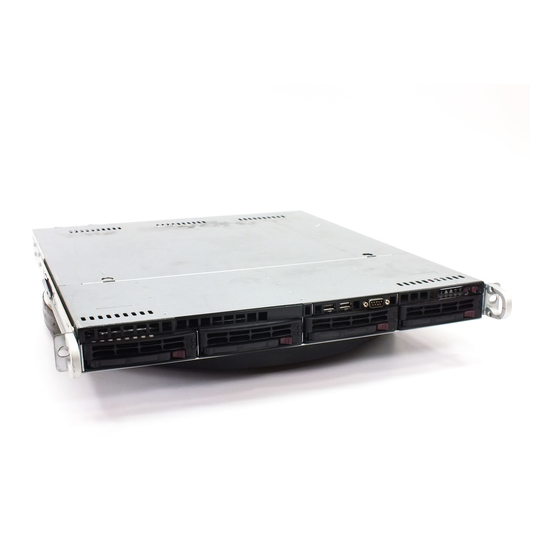
Chapter 1: Introduction Chapter 1 Introduction Overview The Supermicro SuperServer 5015M-MT/5015M-MT+ is a single processor, mini 1U rackmount server. The 5015M-MT/5015M-MT+ is comprised of two main sub- systems: the SC813MFT-300C chassis and the PDSMi/PDSMi+ motherboard. The ® PDSMi/PDSMi+ supports a single Intel processor in an LGA775 type socket and up to 8 GB of DDR2-667/533/400 SDRAM memory. -
Page 12: Motherboard Features
UPER ERVER 5015M-MT/5015M-MT+ User's Manual Motherboard Features At the heart of the SuperServer 5015M-MT/5015M-MT+ lies the PDSMi/PDSMi+, a single processor motherboard designed to provide maximum performance. Below are the main features of the PDSMi/PDSMi+. Chipset Overview The PDSMi is based on Intel’s E7230 chipset and the PDSMi+ is based on Intel's E3000 chipset. -
Page 13: Other Features
Chapter 1: Introduction Onboard Controllers/Ports An onboard IDE controller supports one fl oppy drive and up to two UltraDMA/ATA 100 hard drives or ATAPI devices. Onboard I/O backpanel ports include one serial COM port, a VGA (video) port, two USB ports, PS/2 mouse and keyboard ports and two GLAN (RJ45) ports. - Page 14 UPER ERVER 5015M-MT/5015M-MT+ User's Manual Figure 1-1 . Intel E3000 Chipset (PDSMi+): System Block Diagram Note: This is a general block diagram. Please see Chapter 5 for details. VRM V10.1 LGA775_PROCESSOR VRM 11.0 CK410 CLK FSB: 1066/800/533MHz DDR2 DDR2_667/533/400 PCIE_x8 1x PCIE_x8 Intel 3000 CH_A1-2...
-
Page 15: Server Chassis Features
The following is a general outline of the main features of the SC813MFT-300C chassis. System Power When confi gured as a SuperServer 5015M-MT/5015M-MT+, the SC813MFT-300C chassis includes a single 300W power supply. Control Panel The SC813MFT-300C's control panel provides important system monitoring and control information. -
Page 16: Contacting Supermicro
UPER ERVER 5015M-MT/5015M-MT+ User's Manual Contacting Super Micro Headquarters Address: Super Micro Computer, Inc. 980 Rock Ave. San Jose, CA 95131 U.S.A. Tel: +1 (408) 503-8000 Fax: +1 (408) 503-8008 Email: marketing@supermicro.com (General Information) support@supermicro.com (Technical Support) Web Site: www.supermicro.com Europe Address: Super Micro Computer B.V. -
Page 17: Chapter 2: Server Installation
Server Installation 2-1 Overview This chapter provides a quick setup checklist to get your SuperServer 5015M-MT/ 5015M-MT+ up and running. Following the steps in the order given should enable you to have the system operational within a minimal amount of time. This quick setup assumes that your 5015M-MT/5015M-MT+ system has come to you with the processor and memory preinstalled. -
Page 18: Choosing A Setup Location
UPER ERVER 5015M-MT/5015M-MT+ User's Manual Choosing a Setup Location - Leave enough clearance in front of the rack to enable you to open the front door completely (~25 inches). - Leave approximately 30 inches of clearance in the back of the rack to allow for suffi... -
Page 19: Rack Mounting Considerations
Chapter 2: Server Installation Rack Mounting Considerations Ambient Operating Temperature If installed in a closed or multi-unit rack assembly, the ambient operating tempera- ture of the rack environment may be greater than the ambient temperature of the room. Therefore, consideration should be given to installing the equipment in an environment compatible with the manufacturer’s maximum rated ambient tempera- ture (Tmra). -
Page 20: Installing The System Into A Rack
Identifying the Sections of the Rack Rails You may have received rack rail hardware with the SuperServer 5015M-MT/5015M- MT+. (Two front inner rails should already be attached to the chassis.) This hardware consists of two rear inner rails that secure to the chassis, one on each side just behind the preinstalled front inner rails. -
Page 21: Installing The Rack Rails
Figure 2-1. Installing Rear Inner Chassis Rails Installing the Rack Rails Determine where you want to place the SuperServer 5015M-MT/5015M-MT+ in the rack (see Rack and Server Precautions in Section 2-3). Position the chassis rail guides at the desired location in the rack, keeping the sliding rail guide facing the inside of the rack. -
Page 22: Installing The Server Into The Rack
UPER ERVER 5015M-MT/5015M-MT+ User's Manual Installing the Server into the Rack You should now have rails attached to both the chassis and the rack unit. The next step is to install the server into the rack. Do this by lining up the rear of the chas- sis rails with the front of the rack rails. -
Page 23: Installing The Server Into A Telco Rack
Chapter 2: Server Installation Installing the Server into a Telco Rack To install the 5015M-MT/5015M-MT+ into a Telco type rack, use two L-shaped brackets on either side of the chassis (four total). First, determine how far follow the server will extend out the front of the rack. Larger chassis should be positioned to balance the weight between front and back. -
Page 24: 2-5 Checking The Motherboard Setup
UPER ERVER 5015M-MT/5015M-MT+ User's Manual 2-5 Checking the Motherboard Setup After you install the 5015M-MT/5015M-MT+ in the rack, you will need to open the unit to make sure the motherboard is properly installed and all the connections have been made. 1. - Page 25 Chapter 2: Server Installation Figure 2-4. Accessing the Inside of the System...
-
Page 26: Checking The Drive Bay Setup
UPER ERVER 5015M-MT/5015M-MT+ User's Manual Checking the Drive Bay Setup Next, you should check to make sure the peripheral drives and the SATA drives and SATA backplane have been properly installed and all essential connections have been made. 1. Accessing the drive bays All drives can be accessed from the front of the server. -
Page 27: Chapter 3: System Interface
Chapter 3: System Interface Chapter 3 System Interface Overview There are several LEDs on the control panel as well as others on the SATA drive carriers to keep you constantly informed of the overall status of the system as well as the activity and health of specifi... -
Page 28: Control Panel Leds
UPER ERVER 5015M-MT/5015M-MT+ User's Manual Control Panel LEDs The control panel located on the front of the SC813MFT-300C chassis has fi ve LEDs. These LEDs provide you with critical information related to different parts of the system. This section explains what each LED indicates when illuminated and any corrective action you may need to take. -
Page 29: Power
Chapter 3: System Interface Power: Indicates power is being supplied to the system's power supply units. This LED should normally be illuminated when the system is operating. Serial ATA Drive Carrier LED Each Serial ATA drive carrier has a green LED. When illuminated, this green LED (on the front of the Serial ATA drive carrier) indicates drive activity. - Page 30 UPER ERVER 5015M-MT/5015M-MT+ User's Manual Notes...
-
Page 31: Chapter 4: System Safety
Electrical Safety Precautions Basic electrical safety precautions should be followed to protect yourself from harm and the SuperServer 5015M-MT/5015M-MT+ from damage: Be aware of the locations of the power on/off switch on the chassis as well as the room's emergency power-off switch, disconnection switch or electrical outlet. -
Page 32: General Safety Precautions
Contact technical support for details and support. General Safety Precautions Follow these rules to ensure general safety: Keep the area around the SuperServer 5015M-MT/5015M-MT+ clean and free of clutter. The SuperServer 5015M-MT/5015M-MT+ weighs approximately 38 lbs. (17.2 kg) when fully loaded. When lifting the system, two people at either end should lift slowly with their feet spread out to distribute the weight. -
Page 33: Esd Precautions
Chapter 4: System Safety After accessing the inside of the system, close the system back up and secure it to the rack unit with the retention screws after ensuring that all connections have been made. ESD Precautions Electrostatic discharge (ESD) is generated by two objects with different electrical charges coming into contact with each other. -
Page 34: Operating Precautions
UPER ERVER 5015M-MT/5015M-MT+ User's Manual Operating Precautions Care must be taken to assure that the chassis cover is in place when the 5015M-MT/5015M-MT+ is operating to assure proper cooling. Out of warranty damage to the 5015M-MT/5015M-MT+ system can occur if this practice is not strictly followed. -
Page 35: Chapter 5: Advanced Motherboard Setup
Chapter 5: Advanced Motherboard Setup Chapter 5 Advanced Motherboard Setup This chapter covers the steps required to install the PDSMi/PDSMi+ motherboard into the SC813MFT-300C chassis, connect the data and power cables and install add-on cards. All motherboard jumpers and connections are also described. A layout and quick reference chart are included in this chapter for your reference. -
Page 36: Motherboard Installation
UPER ERVER 5015M-MT/5015M-MT+ User's Manual Unpacking The motherboard is shipped in antistatic packaging to avoid electrical static dis- charge. When unpacking the board, make sure the person handling it is static protected. Motherboard Installation This section explains the fi rst step of physically mounting the PDSMi/PDSMi+ into the SC813MFT-300C chassis. -
Page 37: Connecting Cables
Chapter 5: Advanced Motherboard Setup Connecting Cables Now that the motherboard is installed, the next step is to connect the cables to the board. These include the data (ribbon) cables for the peripherals and control panel and the power cables. Connecting Data Cables The ribbon cables used to transfer data from the peripheral devices have been care- fully routed to prevent them from blocking the fl... -
Page 38: I/O Ports
UPER ERVER 5015M-MT/5015M-MT+ User's Manual Figure 5-1. Control Panel Header Pins Ground x (Key) x (Key) Power On LED Vcc 5V Stby IDE/SATA LED Vcc 3V NIC1 LED Vcc 3V Stby NIC2 LED Vcc 3V Stby OH/Fan Fail LED Vcc 3V Reserved Reserved Ground... -
Page 39: Installing The Processor And Heatsink
Chapter 5: Advanced Motherboard Setup Installing the Processor and Heatsink Avoid placing direct pressure to the top of the processor package. Always remove the power cord fi rst before adding, removing or changing any hardware components. The PDSMi/PDSMi+ has a single LGA775 socket. Please refer to Supermicro's website for supported processors. - Page 40 UPER ERVER 5015M-MT/5015M-MT+ User's Manual North Center Edge Step 4 4. Use your thumb and index fi nger to hold the CPU at the north center and south center edges of the CPU. 5. Align Pin 1 of the CPU with Pin 1 of the socket.
- Page 41 Chapter 5: Advanced Motherboard Setup Installing the Heatsink To install the heatsink, do not apply any thermal compound to the heatsink or CPU die - the proper amount has already been applied. See Figure 5-3. 1. The heatsink that came with the system includes a heatsink retention bracket. From the underside of the board, insert the retention bracket into the four holes surrounding the CPU socket on the board.
-
Page 42: Installing Memory
UPER ERVER 5015M-MT/5015M-MT+ User's Manual Installing Memory CAUTION! Exercise extreme care when installing or removing DIMM modules to prevent any possible damage. Memory support The PDSMi/PDSMi+ supports dual-channel, unbuffered ECC DDR2-667/533/400 SDRAM. Both interleaved and non-interleaved memory confi gurations are sup- ported, so you may populate any number of DIMM slots. -
Page 43: Adding Pci Add-On Cards
Chapter 5: Advanced Motherboard Setup Figure 5-4. DIMM Installation Notch Notch Release Release Note: Notches should align with their receptive points on the slot To Install: Insert module vertically and press down until it snaps into place. Pay attention to the bottom notches. -
Page 44: Motherboard Details
UPER ERVER 5015M-MT/5015M-MT+ User's Manual Motherboard Details Figure 5-5. PDSMi/PDSMi+ Layout (not drawn to scale) FAN6/CPU FAN1 JPW2 JPW1 KB/MS USB1/2 LGA 775 COM1 E7230 CPU Socket North Bridge JLAN1 JLED DIMM1A (Blue) DIMM1B (Black JLAN2 DIMM2A (Blue) DIMM2B (Black) FAN5 FAN2 SXB PCI-E x8... -
Page 45: Pdsmi/Pdsmi+ Quick Reference
Chapter 5: Advanced Motherboard Setup PDSMi/PDSMi+ Quick Reference Jumpers Description Default Setting Int./Ext. Speaker Pins 3-4 (Internal Spkr) JBT1 CMOS Clear See Section 5-10 C1/JI C Bus to PCI Open (Disabled) Compact Flash Master/Slave Closed (Master) Power Force-On Open (Disabled) JPG1 VGA Enable Pins 1-2 (Enabled) -
Page 46: Connector Defi Nitions
UPER ERVER 5015M-MT/5015M-MT+ User's Manual Connector ATX Power 24-pin Connector Pin Defi nitions (JPW1) Defi nitions Pin# Defi nition Pin # Defi nition +3.3V +3.3V Main ATX Power Supply -12V +3.3V Connector PS_ON The primary power supply connector (JPW1) meets the SSI (Superset ATX) 24-pin specifi... -
Page 47: Overheat Led
Chapter 5: Advanced Motherboard Setup Overheat LED (OH) OH/Fan Fail LED Pin Defi nitions (JF1) Pin# Defi nition Connect an LED to the OH connection on pins 7 and 8 of JF1 to provide ad- vanced warning of chassis overheat- Ground ing. -
Page 48: Power On Led
UPER ERVER 5015M-MT/5015M-MT+ User's Manual Power On LED Power LED Pin Defi nitions (JF1) The Power On LED connector is lo- Pin# Defi nition cated on pins 15 and 16 of JF1 (use 5V Stby JLED for a 3-pin connector). This Control connection is used to provide LED indication of power being supplied to... -
Page 49: Chassis Intrusion
Chapter 5: Advanced Motherboard Setup Chassis Intrusion Chassis Intrusion Pin Defi nitions (JL1) The Chassis Intrusion header is des- Pin# Defi nition ignated JL1. See the board layout for Intrusion Input the location of JL1 and the table on Ground the right for pin defi... -
Page 50: Serial Ports
UPER ERVER 5015M-MT/5015M-MT+ User's Manual Serial Ports Serial Port Pin Defi nitions (COM1/COM2) Two serial ports are included on the Pin # Defi nition Pin # Defi nition motherboard. COM1 is a backpanel port and COM2 is a header located beside the PCI slot. -
Page 51: 5-10 Jumper Settings
Chapter 5: Advanced Motherboard Setup 5-10 Jumper Settings Explanation of Jumpers Connector To modify the operation of the mother- Pins board, jumpers can be used to choose between optional settings. Jumpers create shorts between two pins to Jumper change the function of the connector. Pin 1 is identifi... -
Page 52: Jlan1 Enable/Disable
UPER ERVER 5015M-MT/5015M-MT+ User's Manual JLAN1 Enable/Disable JLAN1 Enable/Disable Jumper Settings (JPL1) Change the setting of jumper JPL1 to Jumper Setting Defi nition enable or disable the JLAN1 Ethernet Open Enabled port on the motherboard. See the Pins 2-3 Disabled table on the right for jumper settings. -
Page 53: Vga Enable/Disable
Chapter 5: Advanced Motherboard Setup VGA Enable/Disable VGA Enable/Disable Jumper Settings (JPG1) JPG1 allows you to enable or disable Jumper Setting Defi nition the VGA port. The default position is Pins 1-2 Enabled on pins 1 and 2 to enable VGA. See Pins 2-3 Disabled the table on the right for jumper set-... -
Page 54: 5-11 Onboard Indicators
UPER ERVER 5015M-MT/5015M-MT+ User's Manual 5-11 Onboard Indicators JLAN LED Connection Speed Indicator LED Color Defi nition LAN LEDs 10 MHz The Ethernet ports (located beside the Green 100 MHz VGA port) have two LEDs. On each Amber 1 GHz Gigabit LAN port, one LED indicates activity when blinking while the other LED may be green, amber or off to... -
Page 55: 5-12 Parallel Port And Peripheral Drive Connections
Chapter 5: Advanced Motherboard Setup 5-12 Parallel Port and Peripheral Drive Connections Use the following information to connect the IDE hard disk drive cables. • A red mark on a wire typically designates the location of pin 1. • The 80-wire ATA100/66 IDE hard disk drive cable that came with your system has two connectors to support two drives. -
Page 56: Floppy Connector
UPER ERVER 5015M-MT/5015M-MT+ User's Manual Floppy Connector Floppy Drive Connector Pin Defi nitions (J27) The fl oppy connector is located Pin# Defi nition Pin # Defi nition near PCI- slot. See the table at Ground FDHDIN right for pin defi nitions. Ground Reserved FDEDIN... -
Page 57: Ide Connector
Chapter 5: Advanced Motherboard Setup IDE Connector There are no jumpers to confi gure the onboard IDE interface. See the table below for pin defi nitions. IDE Drive Connectors Pin Defi nitions (J3) Pin# Defi nition Pin # Defi nition Reset IDE Ground Host Data 7... - Page 58 UPER ERVER 5015M-MT/5015M-MT+ User's Manual Notes 5-24...
-
Page 59: Chapter 6: Advanced Chassis Setup
Chapter 6: Advanced Chassis Setup Chapter 6 Advanced Chassis Setup This chapter covers the steps required to install components and perform main- tenance on the SC813MFT-300C chassis. For component installation, follow the steps in the order given to eliminate the most common problems encountered. If some steps are unnecessary, skip ahead to the step that follows. -
Page 60: Control Panel
UPER ERVER 5015M-MT/5015M-MT+ User's Manual Figure 6-1. Chassis Front View Figure 6-2. Chassis Rear View Control Panel The control panel (located on the front of the chassis) must be connected to the JF1 connector on the motherboard to provide you with system control buttons and status indicators. -
Page 61: System Fans
Chapter 6: Advanced Chassis Setup System Fans Three 40-mm high-performance fans provide the cooling for the SuperServer 5015M-MT/5015M-MT+. The chassis includes air seals under the fans and at the chassis cross section, which separates the drive bay area from the motherboard area of the chassis to promote better airfl... -
Page 62: Accessing The Drive Bays
UPER ERVER 5015M-MT/5015M-MT+ User's Manual Accessing the Drive Bays SATA Drives: Because of their hotswap capability, you do not need to access the inside of the chassis or power down the system to install or replace SATA drives. Proceed to the next step for instructions. Note: The operating system you use must have RAID support to enable the hot- swap capability of the SATA drives. - Page 63 Chapter 6: Advanced Chassis Setup 2. Installing/removing hot-swap SATA drives The SATA drive carriers are all easily accessible at the front of the chassis. These are (with RAID enabled) hot-swap drives, meaning they can be removed and in- stalled without powering down the system. To remove a carrier, push the release button located beside the drive LEDs.
-
Page 64: Cd-Rom Drive Installation
UPER ERVER 5015M-MT/5015M-MT+ User's Manual CD-ROM Drive Installation The top cover of the chassis must be opened to gain full access to the CD-ROM drive bay. The 5015M-MT/5015M-MT+ accomodates only slim CD-ROM drives. Side mounting brackets are needed to mount a slim CD-ROM drive in the 5015M- MT/5015M-MT+ server. -
Page 65: Power Supply
Chapter 6: Advanced Chassis Setup Power Supply The SuperServer 5015M-MT/5015M-MT+ has a single 300 watt power supply. This power supply has the capability of operating at 100 - 240 input volts. Depress the main power button on the front of the chassis and then unplug the AC power cord to completely remove power from the system before removing the power supply. - Page 66 UPER ERVER 5015M-MT/5015M-MT+ User's Manual Notes...
-
Page 67: Chapter 7: Bios
Chapter 7: BIOS Chapter 7 BIOS Introduction This chapter describes the Phoenix BIOS™ Setup utility for the PDSMi/PDSMi+. The Phoenix ROM BIOS is stored in a fl ash chip and can be easily upgraded using a fl oppy disk-based program. Note: Due to periodic changes to the BIOS, some settings may have been added or deleted and might not yet be recorded in this manual. -
Page 68: Running Setup
UPER ERVER 5015M-MT/5015M-MT+ User's Manual Running Setup *Default settings are in bold text unless otherwise noted. The BIOS setup options described in this section are selected by choosing the appropriate text from the main BIOS Setup screen. All displayed text is described in this section, although the screen display is often all you need to understand how to set the options (see on next page). -
Page 69: Main Setup Features
Chapter 7: BIOS Main BIOS Setup Menu Main Setup Features System Time To set the system date and time, key in the correct information in the appropriate fi elds. Then press the <Enter> key to save the data. System Date Using the arrow keys, highlight the month, day and year fi... - Page 70 UPER ERVER 5015M-MT/5015M-MT+ User's Manual Legacy Diskette A This setting allows the user to set the type of fl oppy disk drive installed as diskette A. The options are Disabled, 360Kb 5.25 in, 1.2MB 5.25 in, 720Kb 3.5 in, 1.44/1.25MB, 3.5 in and 2.88MB 3.5 in.
- Page 71 Chapter 7: BIOS Primary IDE Master/Slave, Secondary IDE Master/Slave, or Primary IDE Master/Slave, SATA Port 1, SATA Port 2,SATA Port 3, SATA Port 4 These settings allow the user to set the parameters of Primary IDE Master/ Slave and Secondary IDE Master/Slave slots. Hit <Enter> to activate the following sub-menu screen for detailed options of these items.
- Page 72 UPER ERVER 5015M-MT/5015M-MT+ User's Manual CHS Format The following items will be displayed by the BIOS: TYPE: This item displays the type of CPU. Cylinders: This item indicates the status of Cylinders. Headers: This item indicates the number of headers. Sectors: This item displays the number of sectors.
-
Page 73: Advanced Setup
Chapter 7: BIOS Advanced Setup Choose Advanced from the Phoenix BIOS Setup Utility main menu with the arrow keys. You should see the following display. The items with a triangle beside them have sub menus that can be accessed by highlighting the item and pressing <Enter>. Options for PIR settings are displayed by highlighting the setting option using the arrow keys and pressing <Enter>. - Page 74 UPER ERVER 5015M-MT/5015M-MT+ User's Manual Power Button Behavior If set to Instant-Off, the system will power off immediately as soon as the user hits the power button. If set to 4-sec., the system will power off when the user presses the power button for 4 seconds or longer. The options are instant-off and 4-sec override.
- Page 75 Chapter 7: BIOS Cache Video BIOS Area This setting allows you to designate a reserve area in the system memory to be used as a Video BIOS buffer to allow the BIOS write (cache) its data into this reserved memory area. Select "Write Protect" to enable the function and this area will be reserved for Video BIOS ROM access only.
- Page 76 UPER ERVER 5015M-MT/5015M-MT+ User's Manual Discrete MTRR Allocation If enabled, MTRRs (-Memory Type Range Registers) are confi gured as distinct, separate units and cannot be overlapped. If enabled, the user can achieve better graphic effects when using a Linux graphic driver that requires the write- combining confi...
- Page 77 Chapter 7: BIOS Large Disk Access Mode This setting determines how large hard drives are to be accessed. The options are DOS or Other (for Unix, Novelle NetWare and other operating systems). Advanced Chipset Control Access the submenu to make changes to the following settings. Warning : Take caution when changing the Advanced settings.
- Page 78 UPER ERVER 5015M-MT/5015M-MT+ User's Manual Advanced Processor Options Access the submenu to make changes to the following settings: CPU Speed The feature allows the BIOS to display the CPU Speed. Frequency Ratio This feature allows the user to select the ration for the internal frequency multiplier of the CPU.
- Page 79 Chapter 7: BIOS Adjacent Cache Line Prefetch The CPU fetches the cache line for 64 bytes if Disabled. The CPU fetches both cache lines for 128 bytes as comprised if Enabled. C1 Enhanced Mode (*Available when supported by the CPU.) Set to Enabled to enable the Enhanced Halt State.
- Page 80 UPER ERVER 5015M-MT/5015M-MT+ User's Manual I/O Device Confi guration Access the submenu to make changes to the following settings. KBC Clock input This setting allows you to set the clock frequency for the Keyboard Clock. The options are 6MHz, 8MHz, 12 MHz and 16MHz. Serial Port A This setting allows you to decide how Serial Port A is controlled.
- Page 81 Chapter 7: BIOS Mode This feature allows the user to set the mode for the Parallel Port. The options are Output Only, Bi-Directional, EPP and ECP. DMA Channel This feature allows the user to select the DMA Channel for the Parallel Port. The options are DMA1 and DMA3.
- Page 82 UPER ERVER 5015M-MT/5015M-MT+ User's Manual Console Redirection Access the submenu to make changes to the following settings. COM Port Address This item allows you to specify to redirect the console to Onboard COM A or Onboard COM B. This setting can also be Disabled. BAUD Rate This item allows you to select the BAUD rate for console redirection.
- Page 83 Chapter 7: BIOS Serial Port B This setting allows you to assign control of serial port B. The options are Enabled (user defi ned), Disabled, Auto (BIOS controlled) and OS Controlled. Mode Specify the type of device that will be connected to serial port B. The options are Normal, and IR (for an infrared device).
- Page 84 UPER ERVER 5015M-MT/5015M-MT+ User's Manual Hardware Monitor Logic CPU Temperature Threshold This option allows the user to set a CPU temperature threshold that will activate the alarm system when the CPU temperature reaches this pre-set temperature threshold. The options are 75 C, 80 C, 85 C and 90...
-
Page 85: Security
Chapter 7: BIOS Security Choose Security from the Phoenix BIOS Setup Utility main menu with the arrow keys. You should see the following display. Security setting options are displayed by highlighting the setting using the arrow keys and pressing <Enter>. All Security BIOS settings are described in this section. -
Page 86: Boot
UPER ERVER 5015M-MT/5015M-MT+ User's Manual Fixed Disk Boot Sector This setting may offer some protection against viruses when set to Write Protect, which protects the boot sector on the hard drive from having a virus written to it. The other option is Normal. Password on Boot This setting allows you to require a password to be entered when the system boots up. -
Page 87: Exit
Chapter 7: BIOS Exit Choose Exit from the Phoenix BIOS Setup Utility main menu with the arrow keys. You should see the following display. All Exit BIOS settings are described in this section. Exit Saving Changes Highlight this item and hit <Enter> to save any changes you made and to exit the BIOS Setup utility. - Page 88 UPER ERVER 5015M-MT/5015M-MT+ User's Manual Notes 7-22...
-
Page 89: Appendix A: Led Indicators
Appendix A: LED Indicators Appendix A LED Indicators LEDs on the motherboard include a 5V standby power LED and two LEDs used to display POST codes. See the tables below for explanations of the messages as- sociated with these LEDs. A-1 LE1: 5V Standby Power LED 5V Power Standby LED (LE1) State... - Page 90 UPER ERVER 5015M-MT/5015M-MT+ User's Manual Notes...
-
Page 91: Appendix B: Bios Post Codes
Appendix B: BIOS POST Codes Appendix B BIOS POST Codes This section lists the POST (Power On Self Test) codes for the PhoenixBIOS. POST codes are divided into two categories: recoverable and terminal. Recoverable POST Errors When a recoverable type of error occurs during POST, the BIOS will display an POST code that describes the problem. - Page 92 UPER ERVER 5015M-MT/5015M-MT+ User's Manual POST Code Description 8254 timer initialization 8237 DMA controller initialization Reset Programmable Interrupt Controller 1-3-1-1 Test DRAM refresh 1-3-1-3 Test 8742 Keyboard Controller Set ES segment register to 4 GB Auto size DRAM Initialize POST Memory Manager Clear 512 kB base RAM 1-3-4-1 RAM failure on address line xxxx* 1-3-4-3 RAM failure on data bits xxxx* of low byte of memory bus...
- Page 93 Appendix B: BIOS POST Codes POST Code Description Test RAM between 512 and 640 kB Test extended memory Test extended memory address lines Jump to UserPatch1 Confi gure advanced cache registers Initialize Multi Processor APIC Enable external and CPU caches Setup System Management Mode (SMM) area Display external L2 cache size Load custom defaults (optional)
- Page 94 UPER ERVER 5015M-MT/5015M-MT+ User's Manual POST Code Description Check for SMART Drive (optional) Shadow option ROMs Set up Power Management Initialize security engine (optional) Enable hardware interrupts Determine number of ATA and SCSI drives Set time of day Check key lock Initialize typematic rate Erase F2 prompt Scan for F2 key stroke...
- Page 95 Appendix B: BIOS POST Codes POST Code Description Re-map I/O and memory for PCMCIA Initialize digitizer and display message Unknown interrupt The following are for boot block in Flash ROM POST Code Description Initialize the chipset Initialize the bridge Initialize the CPU Initialize system timer Initialize system I/O Check force recovery boot...
- Page 96 UPER ERVER 5015M-MT/5015M-MT+ User's Manual Notes...
-
Page 97: Appendix C: Software Installation
Appendix C: Software Installation Appendix C Software Installation After all the hardware has been installed, you must fi rst confi gure Intel's ICH7R SATA RAID before you install the Windows Operating System and other software drivers. If you do not wish to confi gure onboard SATA RAID functions, please go directly to Section C-4 on page C-16 for Operating System &... - Page 98 UPER ERVER 5015M-MT/5015M-MT+ User's Manual RAID Confi gurations The following types of RAID confi gurations are supported: RAID 0 (Data Striping): this writes data in parallel, interleaved ("striped") sections of two hard drives. Data transfer rate is doubled over using a single disk. RAID1 (Data Mirroring): an identical data image from one drive is copied to another drive.
- Page 99 Appendix C: Software Installation Using the Intel ICH7R SATA RAID Utility Program 1. Creating, Deleting and Resetting RAID Volumes: a. After the system exits from the BIOS Setup Utility, the system will automatically reboot. The following screen appears after Power-On Self Test. b.
- Page 100 UPER ERVER 5015M-MT/5015M-MT+ User's Manual Creating a RAID 0 Volume: a. Select "Create RAID Volume" from the main menu and press the <Enter> key. The following screen will appear: b. Specify a name for the RAID 0 set and press the <Tab> key or the <Enter> key to go to the next fi...
- Page 101 Appendix C: Software Installation Creating a RAID 1 Volume: a. Select "Create RAID Volume" from the main menu and press the <Enter> key. The following screen will appear: b. Specify a name for the RAID 1 set and press the <Tab> key or the <Enter> key to go to the next fi...
- Page 102 UPER ERVER 5015M-MT/5015M-MT+ User's Manual Creating a RAID 10 (RAID 1+ RAID 0): a. Select "Create RAID Volume" from the main menu and press the <Enter> key. The following screen will appear: b. Specify a name for the RAID 10 set and press <Enter>. c.
- Page 103 Appendix C: Software Installation Creating a RAID 5 Set (Parity): a. Select "Create RAID Volume" from the main menu and press the <Enter> key. The following screen will appear: b. Specify a name for the RAID 5 set and press <Enter>. c.
- Page 104 UPER ERVER 5015M-MT/5015M-MT+ User's Manual Deleting RAID Volume: Warning: Be sure to back up your data before deleting a RAID set. You will lose all data on the disk drives when deleting a RAID set. a. From the main menu, select item2-Delete RAID Volume, and press <Enter>. b.
- Page 105 Appendix C: Software Installation Resetting to Non-RAID and Resetting a RAID HDD Warning: Be cautious when you reset a RAID volume HDD to non- RAID or Resetting a RAID HDD. Resetting a RAID volume HDD or Restting a RAID HDD will reformat the HDD and delete all internal RAID structure on the drive.
- Page 106 UPER ERVER 5015M-MT/5015M-MT+ User's Manual C-2 Installing the Windows XP/2000/2003 for systems with RAID Functions New Operating System-Windows XP/2000/2003 Installation a. Insert Microsoft Windows XP/2000/2003 Setup CD in the CD Driver, and the system will start booting up from CD. b.
- Page 107 Appendix C: Software Installation Note: Click the icons showing a hand writing on paper to view the readme fi les for each item. Click the computer icons to the right of these items to install each item (from top to the bottom) one at a time. After installing each item, you must re-boot the system before moving on to the next item on the list.
- Page 108 UPER ERVER 5015M-MT/5015M-MT+ User's Manual C-3 Installing Intel Application Accelerator Utility a. When the above screen appears, click on the icon marked "Application Accel- erator RAID Edition" on the screen, and the following screen will appear: b. When the above screen appears, click "Next" on the screen, and the following screen will appear: ld i hi h...
- Page 109 Appendix C: Software Installation c. After reading the License Agreement, click "Yes" on the screen, and the following screen will appear: d. Specify the folder that you want the program to be installed in and then, click "Next" to begin the installation process. e.
- Page 110 UPER ERVER 5015M-MT/5015M-MT+ User's Manual f. The following screen will appear to display the status of the Intel Application Ac- celerator RAID Edition Installation. g. Once the Application Accelerator RAID Edition installation is completed, the fol- lowing screen will appear. Click "Finish" and the system will reboot. Note: Once the XP/2000/2003 Operating System is installed, please read the "Re- adme text fi...
- Page 111 Appendix C: Software Installation C-4 Installing the Operating System and other Software Programs After all the hardware has been installed, you must fi rst install the operating system, and then, other software drivers. The necessary drivers are all included on the Supermicro CDs that came packaged with your motherboard.
- Page 112 ERVER 5015M-MT/5015M-MT+ User's Manual Supero Doctor III The Supero Doctor III program is a Web base management tool that supports remote management capability. It includes Remote and Local Management tools. The local management is called SD III Client. The Supero Doctor III program included on the CDROM that came with your motherboard allows you to monitor the environment and operations of your system.
- Page 113 Appendix C: Software Installation Supero Doctor III Interface Display Screen-II (Remote Control) Note: SD III Software Revision 1.0 can be downloaded from our Website at: ftp:// ftp.supermicro.com/utility/Supero_Doctor_III/. You can also download SDIII User's Guide at: http://www.supermicro.com/PRODUCT/Manuals/SDIII/UserGuide.pdf. For Linux, we will still recommend Supero Doctor II.
- Page 114 UPER ERVER 5015M-MT/5015M-MT+ User's Manual Notes C-18...
-
Page 115: Appendix D: System Specifi Cations
Appendix D: System Specifi cations Appendix D System Specifi cations Processors Single Intel processors Note: Please refer to the motherboard specifi cations pages on our web site for updates on supported processors. Chipset 5015M-MT: Intel E7230 5015M-MT+: Intel E3000 BIOS ®... - Page 116 UPER ERVER 5015M-MT/5015M-MT+ User's Manual Motherboard Model: PDSMi/PDSMi+ Form Factor: ATX Dimensions: 12 x 9.6 in (305 x 244 mm) Chassis Model: SC813MFT-300C (1U Rackmount) Dimensions: (WxHxD) 17.2 x 1.7 x 19.85 in. (437 x 43 x 504 mm) System Input Requirements AC Input Voltage: 100-240V AC auto-range Rated Input Current: 4A max Rated Input Frequency: 50 to 60 Hz...
- Page 117 Appendix D: System Specifi cations Regulatory Compliance Electromagnetic Emissions: FCC Class B, EN 55022 Class B, EN 61000-3-2/3-3, CISPR 22 Class B Electromagnetic Immunity: EN 55024/CISPR 24, (EN 61000-4-2, EN 61000-4-3, EN 61000-4-4, EN 61000-4-5, EN 61000-4-6, EN 61000-4-8, EN 61000-4-11) Safety: EN 60950/IEC 60950-Compliant, UL Listed (USA), CUL Listed (Canada), TUV Certifi...
- Page 118 UPER ERVER 5015M-MT/5015M-MT+ User's Manual Notes...
Need help?
Do you have a question about the SUPERSERVER 5015M-MT and is the answer not in the manual?
Questions and answers