Table of Contents
Advertisement
Quick Links
Download this manual
See also:
Installation Manual
Advertisement
Table of Contents
Troubleshooting

Subscribe to Our Youtube Channel
Related Manuals for Bosch Infrared Imager EX80


Summary of Contents for Bosch Infrared Imager EX80
- Page 1 INSTALLATION INSTRUCTIONS EX80/82 Infrared Imager™ MAN-80-82-08...
- Page 2 IMPORTANT SAFETY INSTRUCTIONS Read these instructions. Keep this instruction. Heed all warnings. Follow all instructions. Do not use this apparatus near water. Clean only with dry cloth. Do not block any ventilation openings. Install in accordance with manufacturer instructions. Do not install near any heat sources such as radiators, heat registers, stoves or other apparatus (including amplifiers) that produce heat.
- Page 3 plug does not fit into your outlet, consult an electrician for replacement of the obsolete outlet. 10. Protect the power cord from being walked on or pinched particularly at plugs, convenience receptacles, and the power where they exit from the apparatus. 11.
- Page 4 ® surveillance “The cameras have not been evaluated for surveillance performance.” Bosch Security Systems, Inc. will not be responsible for injuries or damages resulting from the improper installation or use of any product sold by Bosch Security Systems, Inc their agents, distributors or dealers.
- Page 5 PSU box. 3) Contact BOSCH Service Center for further advice.
-
Page 6: Table Of Contents
INDEX – EX80/82 Infrared Imager™ Description………………………………………………...1 Unpacking………………………………………………..2 Parts List…………………………………………………..2 Items Required for Installation………………………….2 Initial Preparations……………………………………….3 Guidelines………………………………………………...3 1. Mounting Bracket Preparation……………….……..…...4 2. Cable/Bracket Insertion.……..……………….………..5 3. Mounting Bracket Attachment……………….…………..6 4. Camera Mounting……….……………….….…………..7 5. Camera Lens Adjustments and Select a Window..…..10 6. LED Array-Power Adjustments………………..…….….13 7. -
Page 7: Description
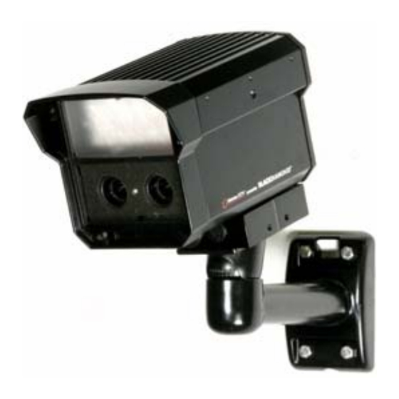
DESCRIPTION The EX80/82 Infrared Imager™ consists of two cameras: color and mono-chrome. These cameras give optimum color performance during daylight conditions and LXR-infrared illuminated performance in the pitch black of night. Both cameras have “Vari-Focal” lenses, and are seamlessly switched by a photocell when light conditions change from day to night, ensuring “No Focus Shift”. -
Page 8: Unpacking
Check the parts list and confirm all items have been located. Inspect the equipment thoroughly to ensure nothing was damaged in transit. Contact BOSCH Service Center if a problem is noted, see the rear page of this booklet for contact numbers. PARTS LIST (items supplied with unit) EX80/82 Infrared Imager™... -
Page 9: Initial Preparations
If any adjustment needed, it is advisable to check the camera’s operation before installation. GUIDELINES The installation of the EX80/82 Infrared Imager™ is explained in Sections 1 to 7. It is important that these steps are followed in numerical order. -
Page 10: Mounting Bracket Preparation
1. MOUNTING BRACKET PREPARATON EXMB.028 Mounting Bracket SET SCREW • Use the supplied Allen Key to remove the setscrew from the supplied mounting bracket. • Separate the two sections of the mounting bracket. -
Page 11: Cable/Bracket Insertion
2. CABLE / BRACKET INSERTION EX82 Camera • Carefully feed the Power/BNC cable through both sections of the mounting bracket. • Make sure the cable is not kinked, chafed, or split during this procedure. -
Page 12: Mounting Bracket Attachment
3. MOUNTING BRACKET ATTACHMENT • Attach the Mounting Bracket to the Camera’s Mounting Block using the six bolts supplied with the bracket. • Snug the two halves of the bracket together with the Allen head set screw. • Tighten the setscrew enough so that the camera can be adjusted for angle. -
Page 13: Camera Mounting
4. CAMERA MOUNTING Warning: this apparatus must be securely attached to the wall or ceiling in accordance with installation instructions. Failure to follow installation instructions may results in injury/death. Select a suitable location that protects the camera from accidental damage, tampering and environmental conditions exceeding the specifications of the camera to be mounted. - Page 14 • Installation should only be performed by skilled personnel Hardware required: • For ceiling mount: Mounting Bracket, Model EXMB.029, Qty = 1 ¼’’ x 2” Lag Screws, Qty = 1 ¼’’ Washer, Qty = 1 • For wall mount: Mounting Bracket, Model EXMB.028, Qty = 1 ¼’’...
- Page 15 mounting using the following wood screws secured into a 2x4 stud under ½” drywall: • wood screws with washer, 1/4” lag, dia Ø1/4”, 2” long, 9 TPI, with ½” head • 16” flat washer. Camera has not been evaluated for safety requirements using other mounting kits.
-
Page 16: Camera Lens Adjustments And Select A Window
5. CAMERA LENS ADJUSTMENTS AND SELECT A WINDOW For optimum picture quality, the camera lenses should be as close as possible to the inside face of the viewing window, without touching. The camera is pre-focused with telephoto setting as factory default. Follow the steps below if any adjustment needed. - Page 17 Lens setscrews 5.1 Vari Focal and “Auto-Iris” Control Adjustments • Loosen the lens set screws for focus/zoom adjustments. • The setscrew marked N ←→ ∞ is used for image focus. • The setscrew marked T←→ W is used for telephoto or wide-angle settings.
- Page 18 Use a Neutral Density filter or Infra-Red Pass filter to cover the lens during focusing to simulate low light conditions on scene for correct 24-hour focusing. For camera with vari- focal lens, the camera should be focused with the lens iris fully opened to simulate the worst possible depth of field.
-
Page 19: Led Array-Power Adjustments
6. LED ARRAY - POWER ADJUSTMENTS If adjustment is needed, remove the rear cover for access to the LRB. The EX80/82 needs to be powered-up while making the LED power adjustments. Cover the photocell to turn the LEDs “ON” (850nm LEDs will have a slight red glow). -
Page 20: Camera Re-Assembly
7. CAMERA RE-ASSEMBLY Make sure all wires are properly connected, all holes are sealed against moisture penetration, and all mounting screws are tight. • Slide the lens foam over the camera lenses. Make sure the foam is snug and as close to the faceplate viewing window as possible and the photocell is secure with an unobstructed view. -
Page 21: Troubleshooting Guide-Camera
8. TROUBLESHOOTING GUIDE -CAMERA PROBLEM POSSIBLE LIKELY SOLUTION CAUSE No Video 1. Power Check the input Supply: power connections at the terminal block, ensuring no wires are Connections loose. …. The supply range is: 12-28VAC OR -Voltage 10.5 – 40VDC. Range... - Page 22 Check the video signal. If okay, the problem is with the interconnections. If still no video, contact BOSCH Service Center. See rear page of this manual for contact information. Poor Picture Quality Increase iris level on lens Dim Image...
- Page 23 Check the coax cable shield is not touching Horizontal Ground “ground”, e.g. at the Scan Lines, Looping on couplings. Rolling Up video cable An electrically or Down isolated circuit board or isolation transformer may be required. Check voltage at input power cable. Must be >10.5VDC or >12VAC.
-
Page 24: Troubleshooting Guide-Leds
- Aim the LEDs directly at an IR “ON” sensitive camera, or use a mirror to see the lights through the EX80/82DXL B/W camera, or wait for the LEDs to warm up (two minutes). - Cover the photo sensor to activate... -
Page 25: Mounting Hole - Diagram
10. Mounting Hole - Diagram • All dimensions expressed in millimeters • 1.59” X 3.38” in inches... -
Page 26: General Specifications
11. GENERAL SPECIFICATIONS Power Consumption: 36W Max. Maximum Current: 2.3A @12Vdc Input Voltage: 24VAC 12VDC Enclosure (housing): Aluminum casting Glass Viewing Window: 130mm H ( 5.12” ) Dimensions: 134.5mm W ( 5.30” 212mm L ( 8.35” ) Operational Temperatures: C to +50 Weight: 2.2kg (4.9 lbs.) Subject to change without notice. - Page 27 Note:...
- Page 28 Phone: +65 6319 3450 Telephone+1 888-289-0096 Phone: + 31 40 2577 284 Fax: +65 6319 3499 +1 585-223-9180 Fax: +31 40 2577 330 apr.securitysystems@bosch.com Email: security.sales@us.bosch.com emea.securitysystems@bosch.com www.boschsecurity.com www.boschsecurity.us www.boschsecurity.com © Bosch Security Systems, Inc. 2009; Data subject to change without notice.
Need help?
Do you have a question about the Infrared Imager EX80 and is the answer not in the manual?
Questions and answers