Table of Contents
Advertisement
Quick Links
Advertisement
Table of Contents
Troubleshooting

Related Manuals for Bosch EX85


Summary of Contents for Bosch EX85
-
Page 1: Installation Instructions
INSTALLATION INSTRUCTIONS EX85 MEGAPIXEL-IP INFRARED IMAGER™ MAN – 85 – 02... -
Page 2: Important Safety Instructions
IMPORTANT SAFETY INSTRUCTIONS Read these instructions. Keep this instruction. Heed all warnings. Follow all instructions. Do not use this apparatus near water. Clean only with dry cloth. Do not block any ventilation openings. Install in accordance with manufacturer instructions. Do not install near any heat sources such as radiators, heat registers, stoves or other apparatus (including amplifiers) that produce heat. - Page 3 Only use attachments/accessories specified by the manufacturer. Use only with the cart, stand, tripod, bracket, or table specified by the manufacturer, or sold with the apparatus. When a cart is used, use caution when moving the cart/apparatus combination to avoid injury from tip-over.
- Page 4 This installation should be made by a qualified service person and conform to all local safety codes. Bosch Security Systems Inc. will not be responsible for injuries or damages resulting from the improper installation or use of any equipment sold by Bosch Security Systems Inc., their agents, distributors or...
- Page 5 PSU box. 3) Contact BOSCH Service Center for further advice.
-
Page 6: Table Of Contents
INDEX – EX85 Megapixel-IP Infrared Imager™ DESCRIPTION................1 UNPACKING ................2 PARTS LIST................2 ITEMS REQUIRED FOR INSTALLATION ......... 2 NETWORK SYSTEM REQUIREMENTS ........3 INITIAL PREPARATIONS............4 GUIDELINES ................4 MOUNTING BRACKET PREPARATON ....5 CABLE / BRACKET INSERTION.......6 MOUNTING BRACKET ATTACHMENT....7 CAMERA MOUNTING ..........8... -
Page 7: Description
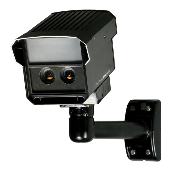
DESCRIPTION The EX85 is the pinnacle of today’s most advanced imaging technologies, combining megapixel sensors, Black Diamond™ night vision technology and IP connectivity. The result is the most advanced level of imaging performance for today’s critical security applications. Crystal clear megapixel color by day delivers images with amazing details. -
Page 8: Unpacking
Check the parts list and confirm all items have been located. Inspect the equipment thoroughly to ensure nothing was damaged in transit. Contact BOSCH Service Center if a problem is noted, see the rear page of this booklet for contact numbers. PARTS LIST... -
Page 9: Network System Requirements
NETWORK SYSTEM REQUIREMENTS A dedicated PC is recommended for receiving image streams from cameras and for archiving and display. Minimum recommended requirements for the PC are as follows: • CPU: Core 2 Duo 2Ghz • RAM: 1GB • Video Card: NVIDIA, 128MB RAM •... -
Page 10: Initial Preparations
GUIDELINES The installation of the EX85 is shown in Sections 1 to 13. It is important that these steps are followed in numerical order. It is also important to follow proper safety guidelines when installing this product. -
Page 11: Mounting Bracket Preparaton
1. MOUNTING BRACKET PREPARATON EXMB.028 (B or W) Mounting Bracket SET SCREW • Use the supplied Allen Key to remove the setscrew from the supplied mounting bracket. • Separate the two sections of the mounting bracket. - 5 -... -
Page 12: Cable / Bracket Insertion
2. CABLE / BRACKET INSERTION EX85 Camera • Carefully feed the Power and Ethernet cables through both sections of the mounting bracket. • Make sure the cables are not kinked, chafed, or split during this procedure. - 6 -... -
Page 13: Mounting Bracket Attachment
3. MOUNTING BRACKET ATTACHMENT • Attach the Mounting Bracket to the Camera’s Mounting Block using the six bolts supplied with the bracket. • Snug the two halves of the bracket together with the Allen head set screw. • Tighten the setscrew enough so that the camera can be adjusted for angle. -
Page 14: Camera Mounting
4. CAMERA MOUNTING Warning: this apparatus must be securely attached to the wall or ceiling in accordance with installation instructions. Failure to follow installation instructions ma results in injury/death. Select a suitable location that protects the camera from accidental damage, tampering and environmental conditions exceeding the specifications of the camera to be mounted. - Page 15 Hardware required: • For ceiling mount: Mounting Bracket, Model EXMB.029, Qty = 1 ¼’’ x 2” Lag Screws, Qty = 1 ¼’’ Washer, Qty = 1 • For wall mount: Mounting Bracket, Model EXMB.028, Qty = 1 ¼’’ x 2” Lag Screws, Qty = 4 Tools required: •...
- Page 16 • wood screws with washer, 1/4” lag, dia Ø1/4”, 2” long, 9 TPI, with ½” head • 16” flat washer. Camera been evaluated safety requirements using other mounting kits. Installation (Ceiling and Wall Mount) • Locate stud in the ceiling/wall and mark outside edges of stud.
-
Page 17: Camera Lens Adjustments
5. CAMERA LENS ADJUSTMENTS For optimum picture quality, the camera lenses should be as close as possible to the inside face of the viewing window, without touching. For focus adjustment follow the steps below. • Loosen the four bolts from the extrusion. •... - Page 18 SETSCREWS 5.1 Focus Control Adjustments • Loosen the lens set screws for focus adjustment. • The setscrew marked N ←→ ∞ is used for image focus. • Re-tighten the setscrews after focus adjustments have been completed. - 12 -...
- Page 19 Use a Neutral Density filter or Infra-Red Pass filter to cover the lens during focusing to simulate low light conditions on scene for correct 24-hour focusing. For camera with vari- focal lens, the camera should be focused with the lens iris fully opened to simulate the worst possible depth of field.
-
Page 20: Led Array - Power Adjustments
6. LED ARRAY - POWER ADJUSTMENTS If adjustment is needed, remove the rear cover for access to the LRB. The EX85 needs to be powered-up while making the LED power adjustments. Cover the photocell to turn the LEDs “ON” (850nm LEDs will have a slight red glow). -
Page 21: Viewing Software Setup
7. VIEWING SOFTWARE SETUP To begin using the viewing software, it must first be installed. To install the software: Make sure any older versions of the program are removed if present on the PC. Run the Setup-EXT5.0.5.13-XP-Vista.exe file and follow the directions to complete the installation. - Page 22 • LocalMachine.exe – viewing and archiving program Both programs are located in the Video Surveillance installation folder. Access to these applications should be granted if the firewall prompts you. - 16 -...
-
Page 23: Application Manager Program
Camera Installer, Video System, and AVI Maker. The firmware loader Camera Upgrade can be listed if the FirmwareLoader.exe file is placed in the “Video Surveillance” folder. The splash screen for the Application Manager is shown below. EX85 Application Manager - 17 -... -
Page 24: Camera Installer
Camera button. The installer will find, configure and verify the operability of the cameras and report installation results. Once the installation is completed, users should press the Save/Exit button to save the installation information. EX85 Camera Installer - 18 -... -
Page 25: Advanced Mode
Advanced Mode In this mode the user can detect all cameras present on the LAN and choose one or more cameras to install. The installer has a mechanism to protect previously installed cameras (if any) from accidental change. IP addresses can also be set manually in this mode if required. - Page 26 Install Selected – function installs selected cameras and verifies operation similarly to the Install Cameras function in Basic mode. Only selected cameras will be installed, and if no cameras are selected, all cameras available will be installed. Unselect All – function deselects all cameras. View Selected –...
-
Page 27: Video System
Video System can be activated by clicking on the Run button in the Application Manager. If Hide is selected, the application will be placed onto the system tray of the Windows taskbar. The main screen for the Video System interface is shown below. EX85 Video System - 21 -... - Page 28 Toolbar The toolbar of the Video System is located in the upper portion of the screen above the video display area, and contains the following icons: Turns on/off a drop-down list of the installed cameras. Cameras can be enabled/disabled by double-clicking on the camera number.
- Page 29 snapshots, right-click on the live video image and select “photo”, “browse”. The directory path to saved snapshots is specified in the settings menu (see below). Alternatively snapshots can be taken by right-clicking on the live video image and selecting “photo”, “save”. Default location for saved images is C:\Program Files\...\Video Surveillance\photo.
- Page 30 live video of the selected area at full resolution. An outline of the selected area will appear in the underlying reduced resolution image. Zooming in and out is performed by pressing the Page Up and Page Down on the keyboard, or by scrolling the mouse wheel (if possible).
-
Page 31: Settings
11. SETTINGS Settings menu is displayed by clicking on the Settings button in the toolbar. The Settings menu is the top level menu for all settings provided in the Video System. Selecting one of the menu items opens a lower level menu containing further settings and options. - Page 32 Camera field Displays the camera number which the settings are being applied to. The list includes an “All cameras” option to apply settings to all cameras. Exposure Displays options to adjust exposure related settings. • Illumination – options to adjust camera’s white balance to differing lighting conditions.
- Page 33 • Single Capture – option halts camera from sending images unless externally triggered from software. - 27 -...
-
Page 34: Image Quality
Image Quality Displays options to adjust image quality settings. • Compression – options to adjust level of JPEG compression to images in different display modes i. Full View is to display full resolution video. ii. Multi View is to display multiple cameras at reduced resolution iii. - Page 35 Image Quality Adjustment Window - 29 -...
-
Page 36: Motion Detection
Archive Displays options to set-up video archival settings. Motion Detection Displays options for configuring motion detection function. There are two main modes supported: a software mode in the Video System, and an on-camera mode. The Video System mode performs analysis on images that have been transmitted from the camera to the computer. - Page 37 larger than the “Limit” setting, motion detection will be ignored. Images below show sample motion detection screen shots. Save To Displays options to specify the directory path for video archives and snapshot images. The name of the archival directory should be the same for all cameras, however it is possible to specify different locations for each camera.
- Page 38 user is able to set different image sizes. Disabling this option allows the increase of the camera frame rate due to smaller image size. • Use DirectX if possible – option to use DirectX functions utilizing graphics card hardware to display images instead of using software.
-
Page 39: Remote Viewing
Authentication Displays options to create user profiles and password protect access to the Video System. There are three levels of access available: • Administrator – grants full access to all features of the Video System • Viewer – grants access to live video and archived video, but not to the settings •... - Page 40 guard should be adjusted to prevent day/night mode toggling during transitional lighting. Auto-Iris This function is not supported as the camera uses manual iris lenses. Therefore, this function should be left DISABLED by leaving the Enabled selection unchecked. Right-Click Menu Right-clicking anywhere within the Video System screen allows opening an additional menu: •...
-
Page 41: Language Selection
Remote Viewing Save to Advanced ii. Camera enables access to the following combined menus: Image Quality Exposure Day/Night Auto-Iris Archive Includes some options in Advanced settings iii. Motion enables access to Motion Settings iv. Printer opens up the Print Setup menu v. - Page 42 Traditional, English, Finnish, German, Japanese, Spanish, Russian and other languages. To select languages, press the F2 button to bring up the language menu. Firmware Loader – Upgrading the Camera Ex85IP cameras are field upgradeable. Firmware Loader is the utility for upgrading the camera’s firmware and/or hardware.
-
Page 43: Default Camera Settings
DEFAULT CAMERA SETTINGS The camera’s settings can be programmed via the supplied software. The screen will show the following window: See page 36 for screen shot - 37 -... - Page 44 Default Camera Settings - 38 -...
-
Page 45: Important Camera Settings
12. IMPORTANT CAMERA SETTINGS Camera Setting Comments Quality Adjusts the level of JPEG compression. There are 21 levels of compression. Different levels of compression can be used in the Display modes different views Full view Multi-view Zoom View Speed Adjusts the rate at which the computer requests images from the camera. -
Page 46: Camera Re-Assembly
13. CAMERA RE-ASSEMBLY Make sure all wires are properly connected, all holes are sealed against moisture penetration, and all mounting screws are tight. • Slide the lens foam over the camera lenses. Make sure the foam is snug and as close to the faceplate viewing window as possible and the photocell is secure with an unobstructed view. -
Page 47: Troubleshooting Guide - Camera
12 - 24V AC/DC. Measure the voltage at the terminal block. Ensure server can Viewer find camera (use find software camera function If still no video, contact BOSCH Service Center. See rear page of this manual for contact information. - 41 -... -
Page 48: Picture Quality
Poor Picture Quality Poor focus Follow directions given in Section 5. Check iris is fully open. Low picture contrast Using viewer software check Auto-Exposure (AE) function is enabled. Using viewer software check shutter settings and increase if necessary. Using viewer software Over check shutter settings exposure... -
Page 49: Troubleshooting Guide - Leds
“ON” - Aim the LEDs directly at an IR sensitive camera, or use a mirror to see the lights through the EX85 camera, or wait for the LEDs to warm up (two minutes). LEDs are not Using the viewer software adjust the... -
Page 50: Mounting Holes - Diagram
16. MOUNTING HOLES – DIAGRAM • All dimensions expressed in millimeters • 1.59” X 3.38” in inches - 44 -... -
Page 51: General Specifications
17. GENERAL SPECIFICATIONS Power Consumption: 48W Max. Maximum Current: 2 Amps Input Voltage: 24VAC Enclosure (housing): Aluminum casting Glass Viewing Window: 130mm H ( 5.12” ) Dimensions: 134.5mm W ( 5.30” ) 212mm L ( 8.35” ) Operational Temperatures: C to +50 Weight: 2.2kg (4.9 lbs.) Subject to change without notice. - Page 52 Phone: +65 6319 3450 Telephone+1 888-289-0096 Phone: + 31 40 2577 284 Fax: +65 6319 3499 +1 585-223-9180 Fax: +31 40 2577 330 apr.securitysystems@bosch.com Email: security.sales@us.bosch.com emea.securitysystems@bosch.com www.boschsecurity.com www.boschsecurity.us www.boschsecurity.com © Bosch Security Systems, Inc. 2009; Data subject to change without notice.
Need help?
Do you have a question about the EX85 and is the answer not in the manual?
Questions and answers