Table of Contents
Advertisement
Quick Links
®
TORNADO
INDUSTRIES
7401 W. LAWRENCE AVENUE
CHICAGO, IL 60706
(708) 867-5100 FAX (708) 867-6968
www.tornadovac.com
Tornado
Operation and Illustrated Parts Manual
For Commercial Use Only
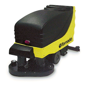
Long-Range Floorkeeper Automatic Scrubber
Catalog No.
99328 & 99332
â
ã2001 Tornado
Form No. L9332AA
2/01
Industries All rights reserved.
Advertisement
Table of Contents
Troubleshooting

Subscribe to Our Youtube Channel
Related Manuals for Tornado 99328


Summary of Contents for Tornado 99328
-
Page 1: Recovery (Vacuum) Tank Assembly - Exploded View
7401 W. LAWRENCE AVENUE CHICAGO, IL 60706 (708) 867-5100 FAX (708) 867-6968 www.tornadovac.com Tornado Operation and Illustrated Parts Manual For Commercial Use Only Long-Range Floorkeeper Automatic Scrubber Catalog No. 99328 & 99332 â ã2001 Tornado Form No. L9332AA 2/01 Industries All rights reserved. -
Page 2: Recovery (Vacuum) Tank Assembly - Exploded View
NOTES... - Page 3 S t a n d a r d W a r r a n t y P r o g r a m * 10 Years: All plastic tanks and rotationally-molded bodies Warranties do not cover 2 Years: components subject Parts on all Tornado and Tornado/Karcher cleaning normal wear or abuse and misuse, and have other 1) 2) equipment limitations specified here.
-
Page 4: Table Of Contents
TABLE OF CONTENTS INTRODUCTION UNIT CONTROLS AND INDICATORS INSTALLATION BATTERY SQUEEGEE RECOVERY TANK DRAIN BRUSHES PRE START-UP FILLING SOLUTION TANK PREVENTATIVE MAINTENANCE PROGRAM INTRODUCTION BATTERY CARE BATTERY CHARGING SQUEEGEE BLADES SQUEEGEE ADJUSTMENT VACUUM AND WATER RECOVERY SYSTEM SOLUTION AND RECOVERY (Vacuum) TANKS VACUUM MOTOR WHEELS LUBRICATING YOUR MACHINE... -
Page 5: Introduction
This manual is designed to instruct your personnel in the operation, maintenance and methods of troubleshooting on your Tornado Floorkeeper. Please read through this manual and keep it handy to ensure that you get maximum satisfaction and value from this new advance in floor care. -
Page 6: Unit Controls And Indicators
Unit Controls and Indicators Control Panel 1. Vacuum Motor Switch 2. Variable Speed Control Knob 3. LCD Display 4. Display Mode Button 5. Brush Pressure Switch Rear Controls 6. Adjustable Solution Control 7. Dual Drive Levers 8. Dual Reverse Buttons 9. - Page 7 Unit Controls and Indicators Display Screens Use the Display Mode Button (to the right of the display) to toggle between three unique screens. Each screen displays a different set of icons and numerical readouts to give you useful information about your Long-Range’s operating status. For particulars on diagnostic fault code information, see page 24.
-
Page 8: Installation
INSTALLATION Batteries Raise top cover using handle, and pivot forward until retainer cords are taut. CAUTION Batteries are heavy. To avoid injury, use two people to lift into position. Place batteries in metal tray liner. Orient each battery exactly as shown in bottom photo, or refer to chart located under the hood. -
Page 9: Squeegee
INSTALLATION Squeegee 1. Make sure squeegee adjustment lever is locked in UP position. Install two adjustment knob assemblies on squeegee assembly. Do not thread in all the way. 2. Slide squeegee assembly on pivot frame and tighten adjustment knobs. 3. Insert hose end into squeegee assembly nozzle throat. -
Page 10: Recovery Tank Drain
INSTALLATION Recovery Tank Drain Install drain door on mounting hardware. Make sure thumb screws are tight. Place top of hose on hose bracket. Brushes 1. Raise brush heads using switch on control panel. 2. Place brushes or pad holders under cover. Locate brush coupler. -
Page 11: Pre Start-Up
PRE START-UP Turn key and power switch on and lower brushes to test. Brush motors will automatically turn on when brushes are lowered. Filling Solution Tank 1. Raise top cover. 2. Always empty recovery tank before filling solution tank. This will eliminate overfilling of recovery tank. -
Page 12: Preventative Maintenance Program
PREVENTIVE MAINTENANCE PROGRAM Introduction This section is designed to instruct your personnel in methods of maintenance on the Tornado Floorkeeper. By following these procedures, repair costs and down time will be greatly reduced. These procedures are for simple repairs that can easily be done by your own personnel. - Page 13 MAINTENANCE CAUTION Do not overfill the battery cells. Do not use a hose or pail. If batteries are accidentally overfilled, remove excess water with the hydrometer provided with the machine. Dispose of excess in accordance with local, state and federal regulations. 3.
-
Page 14: Battery Charging
B.Amber light: All cells are OK but the total battery capacity is reduced. This usually indicates that the batteries are aging. C.Red light: The battery capacity is low and the entire charger/battery system needs to be inspected by a qualified Tornado serviceman. -
Page 15: Squeegee Blades
MAINTENANCE Squeegee Blades 1. If a squeegee blade is worn or ripped, raise the squeegee assembly and remove the entire squeegee assembly. Disconnect vacuum hose, loosen two thumb screws and slide pivot frame out. Remove the wing nuts on the rear of the squeegee housing. -
Page 16: Squeegee Adjustment
MAINTENANCE Squeegee Adjustment 1. Height and flatness adjustments are made by loosening the four screws (A & B) and lifting or lowering the entire squeegee mechanism as desired. 2. Turn machine on and move machine forward slightly. 3. Look down at the contact being made between the squeegee blades and the floor. -
Page 17: Vacuum And Water Recovery System
MAINTENANCE Vacuum and Water Recovery System NOTE: A dirty or clogged filter will greatly reduce suction and ability of machine to recover water. Inspect vacuum filter after each use as follows: 1. Disconnect hose. 2. Turn the two cam-shaped thumb locks. 3. -
Page 18: Vacuum Motor
MAINTENANCE Draining Solution Tank: 1. Locate drain hose at front of unit and position over acceptable floor drain or container. 2.Turn valve handle to open drain valve. 3.Return valve handle to closed position. Tuck drain hose back on machine. Flush and clean tanks after each use and allow to air dry to eliminate odors and corrosion of vacuum motor. -
Page 19: Lubricating Your Machine
Use the appropriate hour meter on the LCD Display to monitor runtimes for each motor. Tornado recommends changing motor brushes at the intervals specified below in order to avoid potential damage to the commutators. Replacement brushes need to be inspected and changed more often due to commutator wear. -
Page 20: Troubleshooting Instructions
TORNADO FLOORKEEPER® TROUBLESHOOTING INSTRUCTIONS This section is designed to instruct your personnel in methods of troubleshooting on the Tornado Floorkeeper. Vacuum System (Poor Suction) During machine operation, if the vacuum motor is running but the solution is not being picked... -
Page 21: Poor Solution Flow
TROUBLESHOOTING 6. Remove vacuum hose from squeegee by pulling hose off squeegee throat. 7. With the vacuum motor on, place your hand over the vacuum hose intake. If suction is strong, a blockage is in the squeegee throat. Clear this blockage by pushing a screwdriver, or any similar tool, downward through the top of the squeegee throat. -
Page 22: Electrical Problems
TROUBLESHOOTING Electrical Problems If brush motors do not run, check the following: 1. Emergency Stop is pulled out. 2. Key switch is in ON position. 3. Power switch is on. 4. Brushes are in down position. 5. Check the circuit breaker button in the back lower panel of the machine. 6. -
Page 23: Troubleshooting Symptoms Chart
4. Keep battery tops clean and dry. 5. Keep water level 1/4” above cell plates. 6. Keep excessive heat and metal away from batteries. 7. Use TORNADO charger with correct voltage and current rating. TROUBLESHOOTING SYMPTOMS Poor Solution Pickup —... -
Page 24: Lcd Display Diagnostic Error Codes
Error codes displayed in the LCD Display indicate that the Electronic Control System may be detecting problems with electrical connections, worn parts, power system controls, or batteries. Be sure to write down the error code before calling your Authorized Tornado Distributor, Service Center, or the Tornado Technical Service Department. -
Page 25: Preventative Maintenance Checklist
MODEL 99328 and 99332 PREVENTIVE MAINTENANCE CHECKLIST START OF OPERATION DAILY MAINTENANCE 1. Unplug charger from Floorkeeper circuitry. 2. Close the solution tank dispenser drain and attach the drain plate to the recovery tank. 3. Assemble and install the vac filter and float cage on the recovery tank. - Page 26 #99328 SQUEEGEE ASSEMBLY – PARTS LIST (Ref drawing 31185) ITEM PART NUMBER DESCRIPTION 01019 NUT - WING 1/4-20 05025 NUT - HEX JAM 07723 WASHER - SPRING ½” 10513 NUT - HEX JAM 14500 SCREW - HEX HEAD CAP 1/2-13 X 2-1/2...
-
Page 27: 32" Squeegee - Exploded View & Parts List
#99332 SQUEEGEE ASSEMBLY – PARTS LIST (Ref. Drawing 31281) ITEM PART NUMBER DESCRIPTION 01019 NUT - WING 1/4-20 05025 NUT - HEX JAM 07723 WASHER – SPRING ½” 10513 NUT - HEX JAM 14500 SCREW - HEX HEAD CAP 1/2-13 X 2-1/2 14817 WHEEL, 4 X 1-1/4 15669... -
Page 28: Squeegee Pivot Frame Assembly - Exploded View
SQUEEGEE PIVOT FRAME ASSEMBLY – EXPLODED VIEW... -
Page 29: Squeegee Pivot Frame Assembly - Parts List
SQUEEGEE PIVOT FRAME PARTS LIST (Ref. Drawing 31184) ITEM PART # DESCRIPTION 00067 NUT - LOCK 5/16-18 01589 NUT - FINISHED HEX 5/16-18 03321 WASHER - PLAIN .391 03418 KNOB, HANDLE 03736 WASHER - PLAIN 3/8 03931 WASHER - PLAIN 5/8 15666 SPACER, SQUEEGEE LIFT 15677... -
Page 30: Solution Control Assembly - Exploded View & Parts List
SOLUTION CONTROL ASSEMBLY PARTS LIST (Ref. Drawing 31180) ITEM PART # DESCRIPTION 01858 SCREW - SLOTTED ROUND HEAD MACHINE #10-24 x 1/4 02568 WASHER-PLAIN 5/16 03395 PIN, COTTER 03418 KNOB, HANDLE 05282 NUT - HEAVY HEX JAM 5/16-18 11007 WASHER - LOCK (lIT) *10 14142 WASHER - PLAIN .265 15677... -
Page 31: Drain & Solution Valves - Exploded View & Parts List
DRAIN VALVE AND SOLUTION VALVE ASSEMBLIES – PARTS LISTS (Ref. Drawings 31074 & 31075) DRAIN VALVE ASSEMBLY ITEM QTY PART NUMBER DESCRIPTION 16680 FITTING, BARBED ELBOW 16681 VALVE, DRAIN SOLUTION VALVE ASSEMBLY ITEM QTY PART # DESCRIPTION 01497 NUT - FINISHED HEX ¼-20 01514 LOCK WASHER 1/4”... -
Page 32: 28" Brush Motor Assembly - Exploded View
99328 BRUSH MOTOR ASSEMBLY – EXPLODED VIEW (Ref. drawing 30877) -
Page 33: 28" Brush Motor Assembly - Parts List
#99328 BRUSH MOTOR ASSEMBLY PARTS LIST (Ref. drawing 30877) ITEM PART # DESCRIPTION 01574 LOCK WASHER ¼” 02568 WASHER-PLAIN 5/16” 03218 WASHER-PLAIN ¼” 03470 RING-RETAINING EXT. “E” ½” (HEAVY DUTY) 03472 RING, RETAINING, 5/8” 03931 WASHER-PLAIN 5/8” 06387 LOCK-WAHER 07723 WASHER-SPRING ½’... -
Page 34: 32" Brush Motor Assembly - Exploded View
#99332 BRUSH MOTOR ASSEMBLY – EXPLODED VIEW (Ref drawing 30913) -
Page 35: 32" Brush Motor Assembly - Parts List
#99332 BRUSH MOTOR ASSEMBLY PARTS LIST (Ref. Drawing 30913) ITEM PART # DESCRIPTION 01574 LOCK WASHER 1/4” 02568 WASHER - PLAIN 5/16 03218 WASHER - PLAIN 1/4 03470 RING - RETAINING EXT. “E” ½” (HEAVY DUTY) 03472 RING, RETAINING. 5/8 03931 WASHER - PLAIN 5/8 06387... -
Page 36: Recovery (Vacuum) Tank Assembly Parts List
RECOVERY (VACUUM) TANK ASSEMBLY PARTS LIST (Ref. Drawing 30868) ITEM QTY PART # DESCRIPTION 00067 NUT - LOCK 5/16-18 01497 NUT - FINISHED HEX 1/4-20 01574 LOCK WASHER 1/4” 01979 SCREW-PHILLIPS ROUND HEAD MACHINE 1/4-20 X 2.00 02568 WASHER - PLAIN 5/16 03218 WASHER - PLAIN 1/4 03397... - Page 37 RECOVERY (VACUUM) TANK DIAGRAM 1 (Ref. Drawing 30868)
- Page 38 RECOVERY (VACUUM) TANK DIAGRAM 2 (Ref. Drawing 30868)
-
Page 39: Solution Tank Assembly - Exploded View & Parts List
SOLUTION TANK ASSEMBLY (Ref. Drawing 30867) ITEM PART # DESCRIPTION 00851 WASHER - PLAIN 1/4” 01497 NUT - FINISHED HEX 1/4-20 01574 LOCK WASHER 1/4” 07741 WASHER - SEALING 1/4 13854 LOCK NUT, 1/4-20 15461 SCREW - SLOTTED ROUND HEAD MACHINE 1/4-20 x 1-1/4 16679 SOLUTION TANK, 25 GAL. -
Page 40: Battery Assembly - Exploded View & Parts List
BATTERY ASSEMBLY PARTS LIST (Ref. Drawing 30862) ITEM PART # DESCRIPTION 16129 NUT - HEX LOCK (KEPS) 1/4-20 16619 SCREW - PHILLIPS TRUSS HEAD MACHINE 1/4-20 X 3/4 16822 BATTERY TRAY - 3 18359 CAST 99512 BATTERY... -
Page 41: Control Panel Assembly - Exploded View & Parts List
CONTROL PANEL ASSEMBLY PARTS LIST (Ref. Drawing 30863) ITEM QTY PART NUMBER DESCRIPTION 18030 SWITCH 18031 SWITCH 18253 SCREW-T.F. PAN HEAD *8-16 X 3/4” 18863 KNOB 30526 BUTTON-REV (MOMENTARY) 30977 CONTROL PANEL (L/R) 30978 SPEED CONTROLLER, DIGITAL 31076 SPEED... -
Page 42: Trigger Assembly - Exploded View & Parts List
TRIGGER ASSEMBLY PARTS LIST (Ref. Drawing 19968) ITEM PART # DESCRIPTION 07741 WASHER – SEALING ¼” 19358 LEVER – HANDLE SWITCH 19593 BRACKET – POTENTIOMETER 19655 SCREW – PHILLIPS PAN HEAD MACHINE #2-56 X ½ 19656 NUT – FINISHED HEX #2-56 19685 SPRING –... -
Page 43: Main View "A" - Major Subassemblies Exploded View
MAIN VIEW “A” – MAJOR SUBASSEMBLIES... -
Page 44: Main View "B" - Exploded View
MAIN VIEW “B” – EXPLODED VIEW (Ref. Drawing 31192) -
Page 45: Main View "B" Parts List
MAIN VIEW “B” PARTS LIST (Ref. Drawing 31192) ITEM QTY PART # DESCRIPTION 00696 WASHER - PLAIN #10 01497 NUT - FINISHED HEX 1/4-20 01574 LOCK WASHER I/4” 02053 SCREW - PHILLIPS ROUND HEAD MACHINE 1/4-20 X 7/8 02217 NUT - HEX JAM LOCK (NYLON INSERT) 1/4-20 02568 WASHER - PLAIN 5/16 03320... -
Page 46: Main View "C" - Exploded View
MAIN VIEW “C” – EXPLODED VIEW (Ref. Drawing 31179) -
Page 47: Main View "C" Parts List
MAIN VIEW “C” PARTS LIST (Ref. Drawing 31179) ITEM QTY PART # DESCRIPTION 01497 NUT - FINISHED HEX 1/4-20 01574 LOCK WASHER 1/4” 02053 SCREW - PHILLIPS ROUND HEAD MACHINE 1/4-20 X 7/8 02568 WASHER - PLAIN 5/16 02958 3/8-16 UNC GRADES 03320 SCREW - HEX HEAD CAP 3/8-16 X I .000 03321... -
Page 48: Cover Assembly - Exploded View & Parts List
COVER ASSEMBLY PARTS LIST (Ref. Drawing 31186) ITEM PART # DESCRIPTION 00600 SCREW – SLOTTED ROUND HEAD MACHINE #8-32 X ¾ 02956 NUT – HEX LOCK (KEPS) #8-32 04735 SCREW – PHILLIPS TRUSS HEAD MACHINE #10-24 X 3/4 10892 NUT – HEX LOCK 15640 WARNING LIGHT 19945...
Need help?
Do you have a question about the 99328 and is the answer not in the manual?
Questions and answers