Table of Contents
Advertisement
Quick Links
Advertisement
Table of Contents

Related Manuals for Kärcher B80W


Summary of Contents for Kärcher B80W
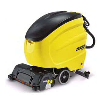
- Page 1 BR/BD 65/80 W (B80W) Service Manual English 5.906-468.0 Rev. 00 (02/09)
-
Page 2: Table Of Contents
Contents Preface Safety instructions Safety Devices Technical Features Drive Brush system Water System Suction system Electrical system Setup and function Front view Rear view Control terminal 4.3.1 Operating elements and displays 4.3.2 Operating panel from below 4.3.3 Drive control Display controls 4.4.1 Open the operator menu 4.4.2... - Page 3 Remove the drive unit Remove the BD brush head Replace the disc brushes on the BD brush head Remove the BR brush head 5.10 Replace the brush rollers on the BR brush head 5.11 Replace the drive belt 5.12 Remove the brush drive on the BR brush head 5.13 Clean water filter.
-
Page 4: Preface
Preface Brush system – Brush head with 2 brush rollers (BR model) or 2 disc brushes Good service work requires extensive and practice-oriented train- (BD model). ing as well as well-structured training materials. Hence we offer regular basic and advanced training programmes covering the entire product range for all service engineers. -
Page 5: Setup And Function
Setup and function Front view 1 Guide handle 2 Drain hose for wastewater 3 Water reservoir 4 Vacuum bar 5 Drive wheel 6 Left scraper roller 7 Right scraper roller 8 Brush head (BD model only) 9 Brush head (BR model) 10 Cover English 5.906-468.0 Rev. -
Page 6: Rear View
Rear view English 5.906-468.0 Rev. 00 (02/09) - Page 7 1 Operator console 14 Lever for adjusting the brush contact pressure 2 Driving lever 15 Pedal for raising/lowering the brush head 3 Guide handle 16 Waterfilter 4 Battery charger (U1) (BAT PACK model) 17 LED (red), fault on battery charger or battery 18 LED (green), battery fully charged 5 Suction hose 6 Vacuum bar...
-
Page 8: Control Terminal
1 Plug (X11) Control terminal 2 Connection terminal (X10), magnetic sensor (B1) 4.3.1 Operating elements and displays 3 Operating panel board (A2) 4 Connection terminal (X9), microswitch suction turbine (M5) and detergent pump (M6) 5 Plug (X7A), ground 6 Key switch (S1) 7 Emergency-stop button (S2) 8 Connection terminal (X7), circuit board (A1) 9 Connection terminal (X8), key switch (S1) and Emergency stop... -
Page 9: Display Controls
Displays the current drive speed in km/ Bürste Displays the current brush contact pressure. This is only displayed while the brush motors are running. Alfred Kärcher Displays the appliance manufacturer. B80W 3.03 Displays the versions of the integrated software. English 5.906-468.0 Rev. 00 (02/09) -
Page 10: Open The Setup Menu
4.4.2 Open the setup menu The display shows "B80W". Quickly tap the info button 3 x with- in one second. The display shows "setup menu". Browse through the setup menu using the rotating function of the info button. A menu point is modified by tapping the info button. The display will blink. -
Page 11: Open The Debug Mode
10 m hours (h) and minutes (m). Speed:0.0km/h Displays the current drive speed in km/ Alfred Kärcher Displays the appliance manufacturer. B80W 3.03 Displays the versions of the integrated software. Pxxx Sxxx Vxxx Pxxx Display of additional electronic infor- mation: Pxxx = speed value (0-255) With max. -
Page 12: Circuit Board (A1)
Circuit board (A1) 15 Main relay (K1) Unscrew the fastening screws (see Chapter 4.2, Item 11) and fold the cover plate back. 16 Connection terminal suction turbine (M5) (plus) 17 Plug (X4A), ground on performance circuit board (A2) 1 Connection terminal (X4) (covered), control board (A2) 18 Covering plate 2 Connection terminal (X3), microswitch (S7), detergent pump (M6), water pump (M4), microswitch (S9), water stop valve (Y1) -
Page 13: Water Filling System (Option)
Water filling system (option) Drain tap for fresh water The stop valve on the fresh water reservoir must be opened in order to empty the fresh water reservoir. Note Only open the stop valve once there is a suitable water drain under the drain valve. -
Page 14: Vacuum Bar
4.11 Cover opened. The microswitch is used and the indicator lamp for the parking brake lights up on the operator panel. 1 Pedal for parking brake 2 Brake (on both sides of the appliance) 3 Microswitch (S9), parking brake 4.10 Vacuum bar 1 Plug for filling opening of fresh water 2 Cover 1 Winch, raise/lower vacuum bar... -
Page 15: Battery
4.12 Battery 4.13 Water stop valve The water stop valve is located under the tank. Drain the water from the fresh water and wastewater tank. Open the tank cover screw. Tilt the tank backwards. The servo motor only opens the water stop valve, if the following conditions are met: –... -
Page 16: Detergent Dosing Pump (Dose)
4.14 Detergent dosing pump (DOSE) The detergent dosing pump is located behind the battery. Drain the water from the fresh water and wastewater tank. Open the tank cover screw. Tilt the tank backwards. Pin 1 Battery voltage 24 Volt (+). Pin 2 24 Volts if the water pump is ON. -
Page 17: Raise/Lower Brush Head
While the brush head is raised, the press spring on the brush head The flowmeter measures the set water volume, after that the cor- pickup is compressed. responding volume of detergent is metered in by switching on the detergent pump. 1 Detergent dosing pump (DOSE) 2 Cover, detergent pump 3 Cap, pump motor... -
Page 18: Water Pump
4.16 Water pump 4.18 Drive The water pumps is located underneath the detergent dosing pump (DOSE). Drain the water from the fresh water and wastewater tank. Tilt the tank backwards. 1 Hose from the water filter 2 Water pump (M4) 3 Hose to the flowmeter 4.17 Discharge flag against static electricity 1 Connection cable, drive motor (M3) -
Page 19: Brush Head (Bd Model)
4.20 Brush head (BD model) 4.21 Brush head, BR model The water distribution bar can be pulled out of the front of the brush head for cleaning. 1 Brush head 2 Cover, belt drive 3 Waste container 4 Lock, bearing lid, left 5 Bearing lid, left 6 Left scraper roller 1 Left mount... -
Page 20: Basic Settings And Service Procedures
Basic settings and service procedures Replace filling system Setting the vacuum Bar Unscrew locking screws. Remove the filling system from the tank. To improve the vacuuming result on tiled floors the vacuum bar can be turned to an oblique position of up to 5°. Release the wing screws. -
Page 21: Clean/Replace The Vacuum Lips
Clean/replace the vacuum lips Check/replace the support roller on the vacuum bar. The support roller is used to prevent the vacuum bar from sucking itself to the floor and so that the vacuum lips do not bend too much. Loosen the fastening screws. Adjust the support roller in the elongated hole accordingly. -
Page 22: Remove The Drive Unit
Remove the drive unit Remove the BD brush head The drive unit consists of a differential gear and an attached drive motor. Release the screw for locking the tank and swing up the tank. Remove the lid of the connector cover on the brush head. Disconnect the connection plug. -
Page 23: Replace The Disc Brushes On The Bd Brush Head
Remove the BR brush head Fold the safety locks on the brush head pickups on the left and right of the brush head up and pull them out of the sides of the pickups. Fold the safety lock on the brush head pickup on top of the brush head down and pull them out of the sides of the pickups. -
Page 24: Replace The Brush Rollers On The Br Brush Head
5.10 Replace the brush rollers on the BR brush head 5.11 Replace the drive belt Remove the bearing lid from the brush roller mount (see Chap- ter 5.10). Unscrew the fastening screws of the drive belt cover and re- move the drive belt cover. Raise the brush head. -
Page 25: Remove The Brush Drive On The Br Brush Head
5.12 Remove the brush drive on the BR brush head 5.13 Clean water filter. Close the stop valve. Unscrew the filter cup. Remove the sieve and rinse it. Assemble in reverse order. Remove the drive belt cover (see Chapter 5.11). Unscrew the fastening screws (arrows) of the brush drive. -
Page 26: Circuit Diagram
Circuit diagram Circuit diagram 0.089-050.0 BAT models English 5.906-468.0 Rev. 00 (02/09) -
Page 27: Circuit Diagram 0.089-051.0 Bat Pack Models
Circuit diagram 0.089-051.0 BAT PACK models English 5.906-468.0 Rev. 00 (02/09) -
Page 28: Legend Of The Electrical Components
Legend of the electrical components Control board Operating panel board Circuit Board, safety sensor (option) Magnetic sensor, drive control B2/B3 Ultrasound sensors, transmitter/receiver (option) LED (green), suction turbine ON LED (green), water pump ON LED (red), brush overload LED (red), wastewater tank full LED (red), brake LED (red), battery Main switch (125 A) -
Page 29: Troubleshooting
Troubleshooting Troubleshooting without display Fault Remedy Appliance cannot be started Stand-by, turn key switch to "0", then set it back to "1". Check fuse F1 *, F2 *, replace if required. * Check battery; charge it if required. Machine does not move Check if the parking brake has been triggered. -
Page 30: Specifications
Specifications Appliance type Appliance no. Circuit diagram operating instruc- Spare parts list tions BR 65/80 W Bp *EU 1.259-120.0 0.089-050.0 5.962-445.0 5.962-558.0 BD 65/80 W Bp *EU 1.259-121.0 0.089-050.0 5.962-445.0 5.962-558.0 BR 65/80 W Bp Pack *EU 1.259-122.0 0.089-051.0 5.962-445.0 5.962-558.0 BD 65/80 W Bp Pack *EU 1.259-123.0...
Need help?
Do you have a question about the B80W and is the answer not in the manual?
Questions and answers