Table of Contents
Advertisement
Quick Links
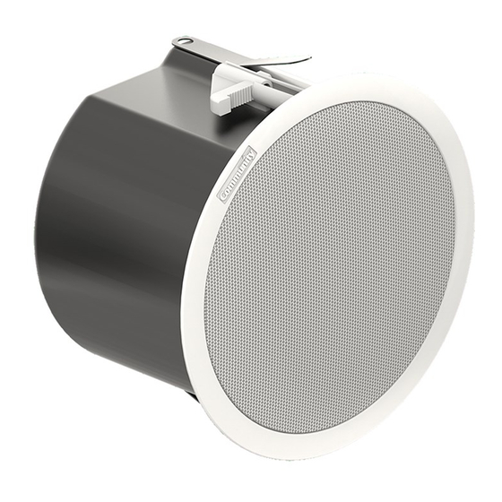
Commercial Design Series
Installation and Operation Manual
Model
C4LP
C4
C6
C6-B
C8
Ceiling Loudspeakers
Loudspeaker Diameter
4.5"
114.3 mm
4.5"
114.3 mm
6.5"
165.1 mm
6.5"
165.1 mm
8.0"
203.2 mm
Description
2-way, low pro ile
2-way, standard pro ile
2-way, standard pro ile
2-way, standard pro ile (black)
2-way, standard pro ile
™
Advertisement
Table of Contents

Subscribe to Our Youtube Channel
Related Manuals for Community C4LP


Summary of Contents for Community C4LP
- Page 1 Commercial Design Series ™ Ceiling Loudspeakers Installation and Operation Manual Model Loudspeaker Diameter Description C4LP 4.5” 114.3 mm 2-way, low pro ile 4.5” 114.3 mm 2-way, standard pro ile 6.5” 165.1 mm 2-way, standard pro ile C6-B 6.5” 165.1 mm 2-way, standard pro ile (black) 8.0”...
- Page 2 The Commercial Design Series is built to cleaner sound since they avoid drive-level satisfy safety agency standards, with quality related distortion. assured by Community’s long history of build- The Commercial Design Series saves you ing high-performance, durable loudspeakers money in several ways. (a) Their powerful...
-
Page 3: Table Of Contents
Figure 3. C4LP Dimensions ........ -
Page 4: Important Safety Instructions
Important Safety Instructions Always follow these basic safety precautions distributor, or call Community directly for as- when using or installing Commercial Design sistance. These terms are de ined below: loudspeakers and accessories: CAUTION: describes an operating condi- • Read these instructions. -
Page 5: L'information De Sûreté Importante
Veuillez lire la section sur le pas à l’installation. Contactez votre detaillant, câblage et l’installation pour des informations distributeur, ou Community directement pour supplémentaires. assistance. Les termes sont dé inies ci-dessous: Community Commercial Design Series... -
Page 6: Unpacking And Inspection
EC STATEMENT OF CONFORMITY This document con irms that the range of products of Community Professional Loudspeakers bearing the CE label meets all of the requirements in the EMC directive 89/336/EEC laid down by the Member States Council for adjustment of legal requirements. Furthermore, the products comply with the rules and regulations referring to the electromagnetic compatibility of devices from 30-August-1995. -
Page 7: Full Ceiling Loudspeaker Assembly (Typical)
Full Ceiling Loudspeaker Assembly (Typical) • Grilles (Qty 2) (Models: C4LP, C4, C6, C6-B and C8) • Cut-out template (can-sized) (Qty 1) • Ceiling Loudspeaker Assembly (Qty 2) • Paint Masks (Qty 2) • Tile Support Bridge Rails (Qty 4) •... -
Page 8: Speci Ications
10.35 “ (263 mm) †The designation NC means do not use this setting when connected to a 100-volt system as it would draw too much power. NC means “No-Connect,” really “do not connect.” Community Commercial Design Series Installation and Operation Manual Page 8... -
Page 9: Figure 3. C4Lp Dimensions
Figure 3. C4LP Dimensions Figure 5. C6/ C6-B Dimensions sions Figure 6. C8 Dimen Figure 4. C4 Dimensions Community Commercial Design Series Installation and Operation Manual Page 9... -
Page 10: Component Identi Ication
Transformer Tap Switch Mounting screw holes on optional can adapter/trim ring Metal safety clip and high-impact mono ilament nylon loops that secure grille to loudspeaker face Figure 7. Component Part Identi ication Community Commercial Design Series Installation and Operation Manual Page 10... -
Page 11: Wiring
The selection of appropriate electri- cal hardware to interface with the Commercial Design Series loudspeaker lies solely with the installation professional. Community recommends that an appropriately licensed engineer, electrician, or other quali ied professional identify and select the appropriate conduit, ittings, wire, etc. -
Page 12: Figure 8. Non-Conduit Guided Wiring To Can And Wire Restraint
(Only use this method when permitted by applicable building and electrical codes!) Conduit itted to the top cover plate of the can, which has a knockout strain relief for this purpose. Figure 9. Conduit for Protected Wiring to Can Community Commercial Design Series Installation and Operation Manual Page 12... -
Page 13: Installing The Loudspeaker In The Ceiling
It is beyond the scope of this manual to provide guidance in this area. Community does, however, offer our Forecast- er HD Distributed Ceiling System Software to assist you in distributed loudspeaker system design. -
Page 14: Figure 12. Position Of Loudspeaker Relative To Bridge Support Rails During Installation
(Temporarily holds unit in place even before Figure 15. Mounting Clamps Shown Grip- you secure it with the mounting clamps) ping Tile Support Bridge Rails After the Clamp Actuators Have Been Tightened. Community Commercial Design Series Installation and Operation Manual Page 14... -
Page 15: Dry-Wall Ceiling Installation
Use the Tile Bridge Support Rails & Spacers An alternative method for new installations – where the ceiling has Retro it an entire Community already been completed – is to use the Tile Commercial Design Series Loudspeaker Bridge Support Rails. While there are in... -
Page 16: Details For Pre-Installation In A New Drywall Ceiling
Failure the Tile Bridge Support Rail atop the ceiling. to do so could result in injury or even Loudspeakers leave the Community factory death in the event of a failure of the with these clamps fully open so that approx- primary mounting support system. -
Page 17: Loudspeaker Tap Setting
70-volt connections. Face-mounted, screwdriver-adjustable Enlarged detail of typical adjustor dial loudspeaker power / voltage setting dial. Figure 18. Setting Loudspeaker Tap Community Commercial Design Series Installation and Operation Manual Page 17... -
Page 18: Painting The Loudspeaker
Note: The paint masks provided by Community remove and that may actually cause damage. are intended to PREVENT the loudspeakers from receiving any paint. -
Page 19: Safety Cabling The Grille
Use the metal clip to link these two mono ila- local codes may vary. Community ment loops. See Figure 18. makes it easy to comply with an 2. -
Page 20: Warranty Information And Service
Authorized Field than the United States of America, contact the Service Station. authorized Community Distributor for your speci ic country or region. Community Professional Loudspeakers 333 East Fifth Street, Chester, PA 19013-4511 USA Tel: 1-(610) 876-3400 | Fax: 1-(610) 874-0190 www.communitypro.com...
Need help?
Do you have a question about the C4LP and is the answer not in the manual?
Questions and answers