
Related Manuals for Community Cloud1299


Summary of Contents for Community Cloud1299
- Page 1 CLOUD12 12-Inch Ceiling Loudspeakers Models: CLOUD1299 / CLOUD1299T CLOUD1266 / CLOUD1266T CLOUD12SUB / CLOUD12SUB-T Installation and Operation Manual...
-
Page 2: Ec Statement Of Conformity
EC STATEMENT OF CONFORMITY This document confirms that the range of products of Community Professional Loudspeakers bearing the CE label meet all of the requirements in the EMC directive 89/336/EEC laid down by the Member States Council for adjustment of legal requirements. Furthermore, the products comply with the rules and regulations referring to the electromagnetic compatibility of devices from 30-August-1995. -
Page 3: Table Of Contents
Figure 13: Knocking out the knockout with a hammer and punch ..............14 Figure 14: Connecting strain relief ......................15 Figure 15: CLOUD1266 and CLOUD1299 input panel (8 ohm operation) ............16 Figure 16: Attaching the loudspeaker cable to the CLOUD12 input panel ............16 Figure 17: CLOUD1266T and CLOUD1299T input panel (70V/100V operation) .......... -
Page 4: Important Safety Information
IMPORTANT SAFETY INFORMATION Always follow these basic safety precautions when using or installing CLOUD12 loudspeakers and accessories: Read these instructions. Keep these instructions. Heed all warnings. Follow all instructions, particularly those pertaining to rigging, mounting, hanging and electrical connections. Only use accessories that are specified and approved by the manufacturer. The terms caution, warning, and danger may be used in this manual to alert the reader to important safety considerations. -
Page 5: Cloud12 Overview
Two-way, full-range 12-inch coaxial ceiling loudspeaker with 60° x CLOUD1266T 60° coverage, 70V/100V operation Two-way, full-range 12-inch coaxial ceiling loudspeaker with 90° x CLOUD1299 90° coverage, 8 ohm operation Two-way, full-range 12-inch coaxial ceiling loudspeaker with 60° x CLOUD1299T 60° coverage, 70V/100V operation 12-inch ceiling mount subwoofer, 360°... -
Page 6: Figure 1: Cloud12 Ceiling Loudspeaker Mounted On A Standard Ported Baffle
C12SQGRL Square white grille for CLOUD12 ceiling loudspeakers RAIL24-PR Pair of 23.75-inch channel rails for CLOUD12 ceiling loudspeakers RAIL30-PR Pair of 30-inch channel rails for CLOUD12 ceiling loudspeakers RAIL48-PR Pair of 47.75-inch channel rails for CLOUD12 ceiling loudspeakers 1/4EYBLTKIT Kit of four (4) 1/4"-20 forged eyebolts Figure 1: CLOUD12 ceiling loudspeaker mounted on a standard ported baffle Figure 2: C12BB3 metal backbox Community CLOUD12 –... -
Page 7: Figure 3: C12Sqgrl Square White Grille
Figure 3: C12SQGRL square white grille Figure 4: Channel rails available in lengths of 23.75 inches, 30 inches and 47.75 inches (sold in pairs) Community CLOUD12 – Installation and Operation Manual - Page 7... -
Page 8: Figure 5: Cloud12 Dimensions
Figure 5: CLOUD12 dimensions Community CLOUD12 – Installation and Operation Manual - Page 8... -
Page 9: Figure 6: Cloud12Sub Dimensions
Figure 6: CLOUD12SUB dimensions Community CLOUD12 – Installation and Operation Manual - Page 9... -
Page 10: Figure 7: C12Bb3 Backbox Dimensions
Figure 7: C12BB3 backbox dimensions Community CLOUD12 – Installation and Operation Manual - Page 10... -
Page 11: Figure 8: C12Sqgrl Grille Dimensions
Figure 8: C12SQGRL grille dimensions Figure 9: RAIL24-PR channel rail dimensions Community CLOUD12 – Installation and Operation Manual - Page 11... -
Page 12: Figure 10: Rail30-Pr Channel Rail Dimensions
Figure 10: RAIL30-PR channel rail dimensions Figure 11: RAIL48-PR channel rail dimensions Community CLOUD12 – Installation and Operation Manual - Page 12... -
Page 13: Cloud12 Assembly
CLOUD12 ASSEMBLY The assembly diagram below illustrates how the CLOUD12 loudspeaker, C12BB3 backbox, C12SQGRL grille and channel rails are assembled together. Please note that the C12BB3 ships as a backbox only, and all other parts shown are optional accessories. Figure 12: CLOUD12 assembly with backbox, grille and channel rails Community CLOUD12 –... -
Page 14: Wiring And Installation
WIRING AND INSTALLATION This manual will serve to assist in wiring and physically mounting CLOUD1266, CLOUD1266T, CLOUD1299, CLOUD1299T, CLOUD12SUB and CLOUD12SUB-T loudspeakers. The directions include assistance to those installers using a complete Community package of loudspeakers and accessories, including the C12BB3 backbox, C12SQGRL square grille and appropriate tile rails. -
Page 15: Connecting Strain Relief To Cable And Loudspeaker Assembly
Connecting Strain Relief to Cable and Loudspeaker Assembly Pass the loudspeaker cable through the appropriate knockout opening in the backbox and secure the cable with a standard electrical tie-wrap (not provided) to provide strain relief (see figures below). Figure 14: Connecting strain relief STRAIN RELIEF PREPARATION TIGHTENING STRAIN RELIEF #1 TIGHTENING STRAIN RELIEF #2... -
Page 16: Connecting The Loudspeaker Cable For 8 Ohm (Low Impedance) Connections
¼” (7mm) and connected to the terminal block. Be careful not to strip too much as frayed wire ends can short across the terminal block. Ring terminals do not fit. Figure 15: CLOUD1266 and CLOUD1299 input panel (8 ohm operation) Figure 16: Attaching the loudspeaker cable to the CLOUD12 input panel... -
Page 17: Connecting The Loudspeaker Cable For 70V/100V Connections
Connecting the Loudspeaker Cable for 70V/100V Connections Connect the common side of the speaker cable to the “common” terminal on the input block. Connect the positive side of the speaker cable to the appropriate 70V/100V wattage tap based on the requirements of the project. -
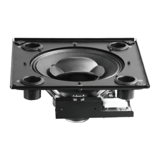
Page 18: Figure 18: Cloud12Sub And Cloud12Sub-T
control the LF driver. The damping factor of an amplifier is dependent largely on its output impedance. A high damping factor indicates that an amplifier will have greater control over the movement of the speaker cone, particularly near the resonant frequency of the driver’s mechanical resonance. -
Page 19: Attaching Channel Rail Kits To The C12Bb3 Backbox
The CLOUD12SUB-T ceiling subwoofer is shipped with a 5-conductor cable for connection to the appropriate autoformer input position. See the figures below for input terminal designation. Figure 20: CLOUD12SUB-T wiring and input panel (70V/100V operation) Attaching Channel Rail Kits to the C12BB3 Backbox Community offers rail kits in three popular lengths: 24 inches, 30 inches and 48 inches. -
Page 20: Figure 21: Channel Rail Kit With Tools And Accessories
Figure 21: Channel rail kit with tools and accessories Instructions for attaching the channel rails to the backbox: Unpack the RAIL24-PR, RAIL30-PR, or RAIL48-PR kit and find the following contents: Two mounting rails (4) 1/4-20 x 1” Hex Head Screws (4) 1/4”... -
Page 21: Suspending The C12Bb3 Backbox
Figure 22: Tightening the rail kit to the backbox Suspending the C12BB3 Backbox The C12BB3 backbox will generally be installed in tile-based ceiling systems, but can also be installed in open space. Use eyebolt kits (part number 1/4EYBLTKIT) to fasten conventional rigging hardware to the C12BB3. -
Page 22: Figure 23: "Snugging" The ¼-Inch Eyebolts
Figure 23: “Snugging” the ¼-inch eyebolts Eyebolt Suspension: The eyebolts must be screwed in so that the shoulder firmly contacts the surface of the enclosure. In all cases the direction of pull on the eyebolt and mounting point should not exceed a maximum of 45º from the vertical axis of the mounting point hole. -
Page 23: Attaching The Cloud12 Loudspeaker To The C12Bb3 Backbox
Attaching the CLOUD12 Loudspeaker to the C12BB3 Backbox NOTE: The CLOUD12 loudspeaker weighs approximately 20 lbs and the C12BB3 backbox weighs at least 40 lbs. Both are awkward and difficult to handle. Lift the CLOUD12 by the speaker basket or main support backing only; do not use the terminal strip or the autoformer (70V/100V versions only) as a lift point. -
Page 24: Figure 26: Aligning The Cloud12 With The Backbox
the speaker’s paper cone. It will likely require the assistance of a second worker to hold the CLOUD12 speaker assembly. Alternately, a fixture might be devised to safely support the speaker frame while fastening it into the C12BB3. Be sure that the neoprene rubber gasket material surrounding the outer edge of the speaker frame makes contact and seals all the way along the perimeter of the raised square flange on the C12BB3. -
Page 25: Attaching The C12Sqgrl Grille To The Cloud12/C12Bb3 Assembly
Attaching the C12SQGRL Grille to the CLOUD12/C12BB3 Assembly Required tools: • One #2 Philips Screwdriver • Superlative vision and a flashlight to see the tiny black holes behind the grille when inserting the screws • Safety glasses are highly recommended Instructions for attaching the grille to the loudspeaker and backbox assembly: Unpack C12SQGRL and inspect contents to find the following: (1) C12SQGRL white grille... -
Page 26: Warranty Information And Service
WARRANTY INFORMATION AND SERVICE Transferable Warranty "(Limited)” Valid in the USA Only Community CLOUD12 ceiling loudspeakers are warranted in the USA to be free from manufacturing defects in materials and workmanship for a period of five years, as determined by one of the following two methods, whichever is longer: Starting from the date of retail purchase, as noted on the sales receipt from an authorized Community dealer,... - Page 27 the exclusion or limitations of consequential or incidental damages, so the above limitations and exclusions may not apply. This Community warranty is not extended by the length of time which an owner is deprived of the use of the product. Repairs and replacement parts provided under the terms of this warranty shall carry only the remaining portion of the warranty.
- Page 28 Community Professional Loudspeakers 333 East Fifth Street, Chester, PA 19013-4511 USA Tel: 1-(610) 876-3400 | Fax: 1-(610)874-0190 www.communitypro.com © 2008 All Rights Reserved 20081218...
Need help?
Do you have a question about the Cloud1299 and is the answer not in the manual?
Questions and answers