
Related Manuals for Rayburn Heatranger 480D


Summary of Contents for Rayburn Heatranger 480D
- Page 1 WARNING This information is a copy of an original archive, therefore Aga cannot be held responsible for its continued accuracy.
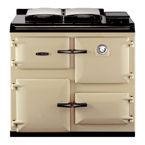
- Page 2 A A t t t t h h e e H H e e a a r r t t o o f f y y o o u u r r H H o o m m e e Heatranger 480D...
- Page 3 To this end, our products are thoroughly tested and examined before despatch. IMPORTANT NOTICE: Any alteration that is not approved by Aga-Rayburn could invalidate the approval of the appliance, operation of the warranty and could affect your statutory rights.
-
Page 4: General Specifications
DESN 510518 GENERAL SPECIFICATIONS Boiler Water Connections Max. Water Temp. 82°C Flow (one) Rp 1 (1in.BSP Int) Return (one) Rp 1 (1in.BSP Int) Water Capacity of 25.5 litres Boiler Both connections are located towards the rear edge of the appliance L.H. side panel. Weight of Appliance 420kg Oil Inlet... - Page 5 Technical Data 480K 480D BOILER BURNER BOILER BURNER COOKER BURNER COOKER BURNER BURNER NOZZLE (US g/h) BURNER NOZZLE (US g/h) 0.60 @ 60°S 0.40 @ 80°SF 0.40 @ 80°SF OIL PRESSURE Bar (psi) OIL PRESSURE Bar (psi) 9.0 (130) 9.0 (130) 9.0 (130) 9.0 (130) OIL BURNING RATE cc/m...
- Page 6 Site requirements INTRODUCTION LOCATION The Rayburn is a floor standing combined cooker and Appliance Hearth. The surface temperature of the floor central heating boiler. It gives independent operation for below the appliance does not exceed 100˚C. The space heating, domestic hot water and cooking.
-
Page 7: Oil Pipe Line
Site requirements OIL PIPE LINE OIL STORAGE The oil supply connection between the storage tank and The minimum recommended oil tank size is 1400 litres the oil pipe should be run in copper or steel pipe with a and the code of practice governing the installation are minimum diameter of 10mm. - Page 8 Site requirements FIG. 1 DESN 510519...
-
Page 9: Flue System
Site requirements FLUE SYSTEM a. Stainless Steel to BS 1449: Part 2 The flue system must be installed to the regulations in b. Cast Iron to BS 41 force. c. Mild Steel, acid resistant vitreous lined to BS 1344: Part Information Maximum flue gas temperature 260˚C (Both burners on) NOTE: TO ACHIEVE THE OPTIMUM OPERATIONAL... -
Page 10: Air Supply
Site requirements AIR SUPPLY AIR SUPPLY The appliance can only be installed in a room which Detailed recommendations for air supply are given in the meets the ventilation regulations in force. But, in any Building Regulations, and in BS 5410: Part 1. The event the room must have a permanent vent of minimum following notes are intended to give general guidance. -
Page 11: Water Circulation System
Site requirements WATER CIRCULATION SYSTEM Suitability The boiler is designed for use on a fully pumped low pressure hot water circulation system, with a pumped over rum facility or alternatively on a sealed system limited to 2 bar. SEE FIG. 3 Space and water heating systems should be in accordance with the relevant recommendation of BS 5410: Part 1. -
Page 12: Heating Controls
Site requirements HEATING CONTROLS Internal temperature and time controls are supplied These provide control of cooking and hot water temperatures. The cooker is supplied with 2-channel programmer:- Channel 1 supplies hot water - Marked “BOILER”. Channel 2 controls the cooker burner - Marked “COOKER”. A separate switch in conjunction with the hot water channel gives priority to either the domestic hot water or the supply of hot water for central heating/DHW (if... -
Page 13: Electrical Supply
Site requirements ELECTRICAL SUPPLY Wiring external to the appliance must be installed in accordance with current National Wiring Regulations and any local regulations which apply. The appliance is supplied for 230 Volt ~ 50Hz and a fuse rating of 3 amps. The method of connection to the mains supply should facilitate complete electrical isolation of the appliance, by the use of a fused double pole switch having a contact... - Page 14 Site requirements FIG. 4...
-
Page 15: Preliminary Installation
Installation requirements CLEARANCES The appliance is floor mounted. The space in which the appliance is to be fitted must have the following minimum dimensions. Between wall and LH side of appliance - 3mm Between wall and RH side of appliance - 10mm Above the raised insulating cover handle - 60mm In addition adequate clearance must be available at the front of the appliance to enable it to be operated and... -
Page 16: Site Location
Installation requirements SITE LOCATION SEE FIG. 7 & 8 1. Check that the hearth is level, then remove the appliance from its transit wooden pallet, and position it with its back against the wall and in its intended position for flue connection. 2. -
Page 17: Burner Access
Commissioning Instructions BURNER ACCESS SEE FIG. 9. 1. Open the burner access door. Remove door and put in a safe place. 2. Remove 4 inner panel securing screws and remove panel. 3 Remove the 3 plinth securing screws and remove plinth. - Page 18 Commissioning Instructions TERMINAL STRIP CONNECTIONS OVEN VENT FAN SPARE NEUTRAL TERMINAL SW/L BOILER SWITCH LIVE TO OPERATE BOILER FROM ROOM STAT OR CYLINDER STAT VIA ZONE VALVES IF FITTED HTG ON TO ROOM STAT/ZONE VALVE(S) ETC ( IF FITTED) FROST STAT (SEE NOTE BELOW) H/W OFF H/W ON TO CYLINDER STAT/ZONE VALVE(S) ETC (IF FITTED).
-
Page 19: Electrical Check
Commissioning Instructions ELECTRICAL CHECK Checks to ensure electrical safety should be carried out by a competent person. FIT PRESSURE GAUGE - SEE FIG. 13 Remove the bleed screw from the manifold and fit an oil pressure gauge with R1/8 connection to check the pump output pressure. -
Page 20: Adjust Oil Pressure
Commissioning Instructions ADJUST OIL PRESSURE - SEE FIG. 13 Whilst the burner is running check the oil pressure on the pressure gauge. With the boiler burner, wait for 30 seconds after ignition, for the burner to establish full firing rate. If the pressure gauge is not indicating the correct reading then adjust the pressure by turning the pressure regulator clockwise to increase or anti-clockwise to decrease the... -
Page 21: Ancillary Controls Check
Commissioning Instructions ANCILLARY CONTROLS CHECK INSTRUCT THE USER Before leaving the site, check the operation of 1. Advise the User of the precautions necessary to programmer, control thermostats are working correctly prevent damage to the heating system and to the building and are capable of controlling the burners correctly. -
Page 22: Sealed System Requirements
Sealed Systems The following fittings should form a permanent part of the system and fitted in the order stated (See Figs. 19 & SEALED SYSTEM REQUIREMENTS 20). See Fig 19. a stop valve complying to the requirements of a. The installation must comply with the requirements of BS 1010: 2. - Page 23 Sealed Systems...
Need help?
Do you have a question about the Heatranger 480D and is the answer not in the manual?
Questions and answers