Table of Contents
Advertisement
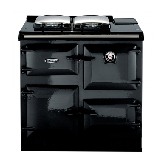
Heatranger 480CD
REMEMBER: when replacing a part on this appliance, use only spare parts that you can be assured
conform to the safety and performance specification that we required. Do not use reconditioned or copy
parts thay have not been clearly authorised by AGA.
PLEASE READ THESE INSTRUCTIONS BEFORE USING THIS APPLIANCE
raywarranty@aga-web.co.uk
DESN 514712
Installation
Instructions
For use in GB and IE
12/15 EINS 514710
Advertisement
Table of Contents

Related Manuals for Rayburn Heatranger 480CD


Summary of Contents for Rayburn Heatranger 480CD
- Page 1 Installation Instructions Heatranger 480CD For use in GB and IE DESN 514712 REMEMBER: when replacing a part on this appliance, use only spare parts that you can be assured conform to the safety and performance specification that we required. Do not use reconditioned or copy parts thay have not been clearly authorised by AGA.
-
Page 2: Table Of Contents
Contents SECTION CONTENTS PAGE CONSUMER PROTECTION HEALTH AND SAFETY SPECIFICATIONS SITE REQUIREMENTS INTRODUCTION REGULATIONS LOCATION GAS SUPPLY ELECTRIC SUPPLY CONTROLS BALANCED FLUE SYSTEM AIR SUPPLY WATER CIRCULATION SYSTEM INSTALLATION INSTRUCTIONS SITE LOCATION CLEARANCES PRELIMINARY INSTALLATION GAS CONNECTION WATER CONNECTIONS SYSTEM SUITABILITY ELECTRICAL CONNECTIONS ELECTRICAL CHECKS WIRING DIAGRAM... -
Page 3: Consumer Protection
Consumer Protection As responsible manufacturers we take care to make sure that our products are designed and constructed to meet the required safety standards when properly installed and used. IMPORTANT NOTICE: PLEASE READ THE ACCOMPANYING WARRANTY Any alteration that is not approved by AGA could invalidate the approval of the appliance, operation of the warranty and could affect your statutory rights. -
Page 4: Specifications
Specifications NOTE: IT IS ADVISABLE TO CHECK THE ACTUAL SIZE/WIDTH OF YOUR CUPBOARDS BEFORE FINALLY FIXING ANY KITCHEN UNITS SINCE ENAMELLED CAST IRON CAN VARY IN SIZE. Fig. 1 DESN 514853 23.4 kW TOTAL BOILER COOKER 480CD NAT. GAS (G20) Max. -
Page 5: Introduction
USED ONLY IN A SUFFICIENT VENTILATION SPACE. normal and not a fault with the appliance. It is therefore advisable to open doors and or windows. This Rayburn Gas combination appliance is a combined cooker and hot water boiler providing central heating GAS SUPPLY and domestic hot water, in addition to special cooking facilities. - Page 6 GAP REQUIRED FOR SERVICING ON LEFT HAND SIDE Fig. 2A MINIMUM GAP ON RIGHT HAND SIDE Fig. 2B WALL PROJECTING BEYOND THE FRONT OF THE APPLIANCE Fig. 2C...
-
Page 7: Controls
Site Requirements The air inlet/products outlet duct and the terminal of the boiler MUST NOT be closer than 25mm (1”) to CONTROLS combustible material. Detailed recommendations on the protection of combustible material are given in Independent temperature controls with time switch BS. - Page 8 Site Requirements SEE FIG. 3 The flue system must be installed in accordance with the regulations in force. Terminal Position The minimum acceptable spacings from the terminal to obstructions and ventilations openings are shown in Fig. 5. Where the terminal is within 1m of any plastic material, such material should be protected from the effects of the combustion products of the flue.
-
Page 9: Water Circulation System
Site Requirements WATER CIRCULATION SYSTEM Pressure Loss Curve Space and water heating systems should be in accordance with the relevant recommendations of BS 5410: Part 1. In a combined central heating and domestic hot water system, the hot water storage vessel must be of the indirect cylinder type to BS 1566: Part 1. -
Page 10: Site Location
Installation Instructions SITE LOCATION 1. Remove the appliance assembly from the transit wooden pallet by the temporary location of a sloping ramp board between the pallet and the floor. With the appliance on the floor, lift the front of the appliance (manually or with a crowbar) and insert a 32mm x 1m long tube between the front of the appliance base plate and the floor. -
Page 11: Gas Connection
Installation Instructions GAS CONNECTION 1. Connect the gas supply to the 1/2” BSP tapered thread on the left hand side of the appliance. (22mm copper pipe must be used to within 1 metre of the appliance. 2. Test the hole of the gas installation including the meter and purge in accordance with the relevant recommendations. -
Page 12: Electrical Connections
Installation Instructions ELECTRICAL CONNECTIONS The switch LIVE must be connected to the programmer or room stat. The system pump and mains should be connected as shown in Fig. 8. Fig. 8 DESN 514865 ELECTRICAL CHECKS Checks to ensure electrical safety should be carried out by a qualified engineer. -
Page 13: Wiring Diagram
Installation Instructions Fig. 9... -
Page 14: Condensate Trap
Installation Instructions CONDENSATE TRAP This appliance has a built-in condensate trap, which eliminates the need for any external traps. The flexible drain hose is located on the underside of the boiler. This should be routed through the cutout in the side or back of the appliance. -
Page 15: Exhaust Duct
Balanced Flue Installation EXHAUST DUCT To ensure the boiler flue has been fitted correctly into the boiler flue outlet, remove the glass control facia and THIS APPLIANCE MUST BE INSTALLED WITH THE brackets behind. The boiler elbow can then be adjusted if DUCTS AND TERMINALS SUPPLIED. -
Page 16: Vent Pipe
Balanced Flue Installation Fig. 15 DESN 514871 Fig. 17 DESN 511273 VENT PIPE GUARD If the house wall is thicker than 500mm, an extension kit wil be needed (to be ordered separately). The two A vent pipeguard is supplied with the cooker and must extensions supplied are the same size, one will fit into be fitted if the vent termination is less than 2 metres the boiler without cutting. -
Page 17: Sealed System Requirements
Sealed System SEALED SYSTEM REQUIREMENTS OPEN SYSTEM REQUIREMENTS See Fig. 19 If you are using an open system, the pressure sensor on the flow pipe needs to be wired out of the system. a. The installation must comply with the requirements This is achieved by removing the RED link wire which of BS 6798 and BS 5449. - Page 18 Sealed System Fig. 19...
-
Page 19: Commissioning
Commissioning ELECTRICAL INSTALLATION LIGHTING THE BOILER BURNER Checks to ensure electrical safety should be carried out To light the burner - turn the boiler thermostat to maximum by a competent person i.e. earth continuity, polarity and and create a demand on the room thermostat. resistance to earth. -
Page 20: Cooker Burner Lighting
Commissioning COOKER BURNER LIGHTING Turn the cooker burner to mark H and ensure programmer is set to MANUAL, the burner should light within 60 seconds. COOKER OUTPUT Check within 5 minutes that the gas consumption is ±5% of the stated heat input. 14.6 kW. COMBUSTION Connect a suitable gas analyser to the sample point on the hob or flue outlet. - Page 24 With AGA Rangemaster’s policy of continuous product improvement, the Company reserves the right to change specifications and make modifications to the appliance described at any time. Manufactured by AGA Rangemaster Station Road Ketley Telford Shropshire TF1 5AQ England Tel: 0845 815 2020 www.rayburn-web.co.uk www.agacookshop.co.uk...
Need help?
Do you have a question about the Heatranger 480CD and is the answer not in the manual?
Questions and answers