Movincool Office Pro 12 Service Manual
Hide thumbs
Also See for Office Pro 12:
- Operation manual (76 pages) ,
- Service manual (46 pages) ,
- Specifications (2 pages)
Table of Contents
Advertisement
Quick Links
SERVICE
M A N U A L
OFFICE PRO 12
DENSO SALES CALIFORNIA, INC.
(800) 264-9573
www.movincool.com
REGISTERED TO ISO 9002
FILE NO. A5537
© 2000 DENSO SALES CALIFORNIA, INC.
All rights reserved. This book may not be reproduced or copied, in whole or in part, without the written permission
of the publisher. DENSO SALES CALIFORNIA, INC. reserves the right to make changes without prior notice.
MovinCool is a registerd trademark of DENSO CORPORATION.
DSCA P/N: LA990009-0435-E
Advertisement
Table of Contents

Related Manuals for Movincool Office Pro 12


Summary of Contents for Movincool Office Pro 12
- Page 1 All rights reserved. This book may not be reproduced or copied, in whole or in part, without the written permission of the publisher. DENSO SALES CALIFORNIA, INC. reserves the right to make changes without prior notice. MovinCool is a registerd trademark of DENSO CORPORATION. DSCA P/N: LA990009-0435-E...
-
Page 2: Definition Of Terms
FOREWORD This manual has been published to service the MovinCool Office Pro 12. Please use this service manual only when servicing the Office Pro 12. DEFINITION OF TERMS WARNING: Describes precautions that should be observed in order to prevent injury to the user during installa- tion or unit operation. -
Page 3: General Description
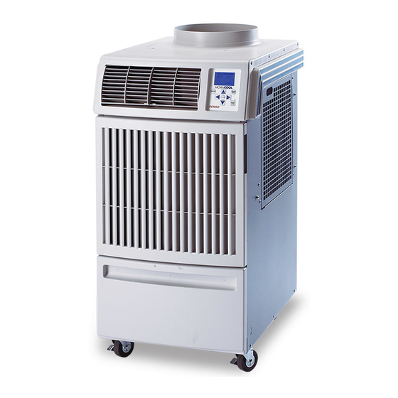
(condenser) to exhaust exchanged heat to the out- doors. Unlike conventional air conditioners, the MovinCool Spot Cooling System is a spot cooler which EVAPORATOR directs cool air to particular areas or objects. - Page 4 CONSTRUCTION AND SPECIFICATIONS EXHAUST AIR DUCT COOL AIR VENT EVAPORATOR CENTRIFUGAL FAN CONDENSER CAPILLARY TUBE DRAIN TANK COMPRESSOR DRAIN SWITCH CONTROL BOX Construction of Office Pro 12 MOVINCOOL OFFICE PRO 12 SERVICE PAGE 4...
- Page 5 CONTROL PANEL TOP PANEL EXHAUST AIR VENT RIGHT HANDLE COOL AIR VENT SIDE PANEL FAN MOTOR FRONT PANEL CONDENSER FAN CAPILLARY TUBE EVAPORATOR COMPRESSOR ACCUMULATOR DRAIN TANK CONDENSER CASTER POWER CORD Construction Diagram MOVINCOOL OFFICE PRO 12 SERVICE PAGE 5...
- Page 6 CONSTRUCTION AND SPECIFICATIONS Basic Construction The MovinCool Spot Cooling System is compact in construction because the con- denser and the evaporator are enclosed in one unit. The interior is divided into three sections. The upper front face is equipped with the evaporator, while the lower front face contains the drain tank.
-
Page 7: Table Of Contents
F (35 C), < 60% ................65 F (18.3 C), > 50% Control Device temperature control ..........included programmable timer ..........included two speed fan............included Specifications Specifications are subject to change without notice. MOVINCOOL OFFICE PRO 12 SERVICE PAGE 7... - Page 8 CONSTRUCTION AND SPECIFICATIONS ø11.575 4.60 2.20 12.40 20.67 16.50 27.40 19.30 Exterior Dimensions (units: inches) MOVINCOOL OFFICE PRO 12 SERVICE PAGE 8...
-
Page 9: Wet Bulb
(59) (68) (77) Wet Bulb Temperature ˚C (˚F) Cooling Capability Curve 35 (95) 30 (86) 25 (77) 20 (68) 15 (59) (59) (68) (77) (86) Wet Bulb Temperature ˚C (˚F) Power Consumption Curve MOVINCOOL OFFICE PRO 12 SERVICE PAGE 9... -
Page 10: Compressor
• Capillary tube These parts are all connected by copper tubing. All the connections have been brazed. EVAPORATOR CONDENSER CAPILLARY TUBE ACCUMULATOR COMPRESSOR REFRIGERANT FLOW CONDENSER ACCUMULATOR CAPILLARY MOTOR TUBE EVAPORATOR COMPRESSOR Refrigerant System MOVINCOOL OFFICE PRO 12 SERVICE PAGE 10... - Page 11 Heat is given off and absorbed by air being pulled across the condenser fins by the centrifugal fan and then expelled through the exhaust air duct. MOVINCOOL OFFICE PRO 12 SERVICE PAGE 11...
- Page 12 This protects the compressor from possible dam- age caused by the intake of liquid refrigerant. To Compressor Accumulator MOVINCOOL OFFICE PRO 12 SERVICE PAGE 12...
- Page 13 CONDENSER INLET PIPE COMPRESSOR EVAPORATOR SUCTION PIPE OUTLET PIPE (Insulated) ASSY COMPRESSOR CAPILLARY TUBE DISCHARGE PIPE CONDENSER OUTLET PIPE CONNECTING TUBE (Condenser to Capillary Tube) CONNECTING PIPE (Evaporator to Compressor) Refrigerant System Piping MOVINCOOL OFFICE PRO 12 SERVICE PAGE 13...
- Page 14 J8 (AUX1) Auxiliary Connector (CPK-3) Capacitor for Compressor AUX2 Auxiliary Connector (not used) RELAY BOARD RELAY BOARD FUSE DIP SWITCH TERMINAL BLOCK COMPRESSOR CAPACITOR CAPACITOR Electrical System and Control Box for Office Pro 12 MOVINCOOL OFFICE PRO 12 SERVICE PAGE 14...
- Page 15 ELECTRICAL SYSTEM Basic Operation Of The Office Pro 12 Electrical Circuit There are two basic components used to control the operation of the Office Pro 12 Electrical System: • Control Panel Assembly • Control Box The Control Panel Assembly contains the Control Panel, Control Board (with inputs for the freeze and room temperature thermistors), drain switch, and a microprocessor.
-
Page 16: Electrical System
Fuse Specifications: 2/10A 250V CAUTION: Failure to use the exact type of fuse could result in damage to the unit and/or to com- ponents. It will also void the warranty of the unit. Relay Board MOVINCOOL OFFICE PRO 12 SERVICE PAGE 16... -
Page 17: Compressor Overload Relay
Specifications: Temperature Variance Trip Time (seconds) Contacts Open 284˚F / 140˚C ± 41˚F / ± 5˚C 2 – 12 Contacts Closed 165˚F / 74˚C ± 48˚F / ± 9˚C MOVINCOOL OFFICE PRO 12 SERVICE PAGE 17... - Page 18 Off” button. The unit will return to the previous Temperature Set Point. Condensate Pump Kit (optional) The Office Pro 12 model comes standard with a drain tank, which collects the water that forms on the evaporator during normal cooling operation. If the unit is required to operate continuously without periodic emptying of this tank, a condensate pump may be needed.
-
Page 19: Temperature Control
When the DIP Switch is set in the “up” or ˚F position, the Set Point and Room Temperature will be dis- played in degrees Farenheit (˚F). The LED that indicates ˚F will also be illuminated (this is the “factory default” setting). MOVINCOOL OFFICE PRO 12 SERVICE PAGE 19... -
Page 20: Troubleshooting And Repair
• Check wire connections • Defective fan motor capacitor Insufficient Cooling • Environmental conditions • Defective fan motor exceed design specifications • Defective Relay Board • Clogged air filter • Defective Control Board MOVINCOOL OFFICE PRO 12 SERVICE PAGE 20... - Page 21 THERMOMETER graphs on page 8, proceed with the remedy suggested in the troubleshooting chart on page COOL AIR OUT THERMOMETER EVAPORATOR AIR IN Cooling Capacity MOVINCOOL OFFICE PRO 12 SERVICE PAGE 21...
- Page 22 Filter Element Room Thermistor Left Panel Blower Housing (evap.) Blower Housing Drain Pan Assy Condenser Fan Rear Panel Freeze Thermistor Drain Tank Panel Assy Service Panel Drain Tank Power Cord Caster Caster Disassembly MOVINCOOL OFFICE PRO 12 SERVICE PAGE 22...
- Page 23 A. Remove drain tank. Removal of Drain Tank B. Remove six (6) screws from upper front panel. Removal of Upper Front Panel Screws C. Slide upper front panel forward and remove. Removal of Upper Front Panel MOVINCOOL OFFICE PRO 12 SERVICE PAGE 23...
- Page 24 Removal of Air Outlet Louver E. Remove four (4) screws from service panel. Removal of Service panel Disconnect the three (3) lead wires of the power cord. DISCONNECT DISCONNECT DISCONNECT Removal of Power Cord Screws MOVINCOOL OFFICE PRO 12 SERVICE PAGE 24...
-
Page 25: Removal Of Electrical Parts
J8 (AUX1) Auxiliary Connector (CPK-3) Capacitor for Compressor AUX2 Auxiliary Connector (not used) RELAY BOARD RELAY BOARD FUSE DIP SWITCH TERMINAL BLOCK COMPRESSOR CAPACITOR CAPACITOR Removal of Electrical Parts in the Control Box MOVINCOOL OFFICE PRO 12 SERVICE PAGE 25... - Page 26 Relay Board to Control Panel (optional) Condensate Pump Kit - CPK-3 Connections to Relay Board Jumper Drain Tank Switch NOT USED Freeze Thermistor Room Thermistor Main Wiring Harness (Control Panel to Relay Board) Connections to Control Board MOVINCOOL OFFICE PRO 12 SERVICE PAGE 26...
- Page 27 Removal of Blower Assembly Control Panel Right Stay Control Panel Left Stay Evaporator Fan Casing Evaporator Fan Motor Stay Middle Frame Sub-Assy Fan Motor Condenser Fan Casing Assy Condenser Fan Ring Sub-Assy Disassembly of Blower MOVINCOOL OFFICE PRO 12 SERVICE PAGE 27...
- Page 28 B - SCREW Removal of Fan Motor Assembly D. Remove the centrifugal fan by loosening the set screw on the shaft. Remove the fan motor by loosening nuts “A”. Removal of Fan Motor MOVINCOOL OFFICE PRO 12 SERVICE PAGE 28...
- Page 29 Removal of Screws for Right Side Panel G. Remove two (2) screws from the control panel stay. Removal of Control Panel H. Remove two (2) screws from the control panel stay. Removal of Control Panel MOVINCOOL OFFICE PRO 12 SERVICE PAGE 29...
- Page 30 WARNING: Properly discharge the capacitor(s) before testing and after testing has been com- pleted. Failure to do so could cause damage to test equipment or the unit and/or result in personal injury (electrical shock) or death. MOVINCOOL OFFICE PRO 12 SERVICE PAGE 30...
- Page 31 The compressor has an external overload relay. The overload relay should be opera- tional if the above resistance is obtained under normal temperature. For Overload Relay Inspection Of Compressor specifications, see chart on Page 17. MOVINCOOL OFFICE PRO 12 SERVICE PAGE 31...
- Page 32 In case the unit is judged to be deficient in cooling capacity, be sure to perform the inspections in 18A and 18B to confirm the cause of trouble. After that, charge the system with refrigerant to the specified amount. MOVINCOOL OFFICE PRO 12 SERVICE PAGE 32...
- Page 33 Since the brazing filler metal flows easily into the portion heated to a proper temperature, it is essential to keep the whole fitting at a proper brazing temperature. MOVINCOOL OFFICE PRO 12 SERVICE PAGE 33...
- Page 34 NOTE: Hold the compressor body, not the tube, when carrying the compressor. PART TO REPLACE DISCONNECT AT Compressor A & B Condenser A & C Capillary Tube D, E, & G Evaporator E & F Refrigeration Cycle Components MOVINCOOL OFFICE PRO 12 SERVICE PAGE 34...
- Page 35 (2) Fit the process tube fitting to the pinch-off tube on both sides. MOVINCOOL OFFICE PRO 12 SERVICE PAGE 35...
- Page 36 (this could also include gauge manifold). Perform leak check according to procedure indicated in 20D. Once leak has been found and repaired evacuate the system once more, and confirm system holds vacuum. MOVINCOOL OFFICE PRO 12 SERVICE PAGE 36...
- Page 37 CAUTION: Be sure to evacuate the system twice or more using the repetitive vacuum method. Evacuate the system an additional time on rainy or humid days. MOVINCOOL OFFICE PRO 12 SERVICE PAGE 37...
- Page 38 Charge to the specified amount, always observing the scale graduations while charging. (5) Close the high pressure valve of the gauge manifold and the valve of the refrigerant cylinder. MOVINCOOL OFFICE PRO 12 SERVICE PAGE 38...
- Page 39 Secure the wires using clamps in the same position they were before re- moval. Perform the inspection of cooling capacity and check for abnormal noise or abnormal vibration. MOVINCOOL OFFICE PRO 12 SERVICE PAGE 39...
- Page 40 TROUBLESHOOTING AND REPAIR Schematic MOVINCOOL OFFICE PRO 12 SERVICE PAGE 40...
Need help?
Do you have a question about the Office Pro 12 and is the answer not in the manual?
Questions and answers