Table of Contents
Advertisement
Advertisement
Table of Contents

Related Manuals for Eurotherm 3100


Summary of Contents for Eurotherm 3100
- Page 1 invensys ® E U R O T H E R M ® Engineering Manual...
- Page 2 The information in this document is given in good faith, but is intended for guidance only. Eurotherm Limited will accept no responsibility for any losses arising from errors in this document.
-
Page 3: Table Of Contents
3200 Series 3200 Series PID Temperature Controllers Engineering Handbook Part Number HA028651 Issue 7.0 Apr-09 Includes 3216, 3208, 32h8 and 3204 Controllers. Contents Installation and Basic Operation ..................... 5 What Instrument Do I Have? ..........................5 Unpacking Your Controller..........................5 Dimensions.................................5 Step 1: Installation ............................6 1.4.1 Panel Mounting the Controller..................................6 1.4.2... - Page 4 3200 Series Level 2 Parameters .............................21 Timer Operation..............................25 Dwell Timer ...............................26 Delayed Timer..............................26 Soft Start Timer ..............................27 Programmer ...............................27 5.8.1 Programmer Servo Mode and Power Cycling.............................. 28 5.8.2 To Operate the Programmer .................................... 28 5.8.3 To Configure the Programmer..................................29 Access to Further Parameters......................30 6.1.1 Level 3.............................................
- Page 5 3200 Series 11.10 Control Parameters............................55 11.11 Auto-tune Configures R2G ..........................57 11.12 Example: To Configure Heating and Cooling ....................58 11.12.1 Effect of Control Action, Hysteresis and Deadband ..........................59 Alarms ............................60 12.1 Types of Alarm..............................60 12.1.1 Alarm Relay Output .......................................62 12.1.2 Alarm Indication ......................................62 12.1.3 To Acknowledge An Alarm ..................................62...
- Page 6 3200 Series 17.2 Connecting a PC to the Controller........................101 17.2.1 Using the H Communications Port................................101 17.2.2 Configuration Clip ......................................101 17.3 Starting iTools..............................102 17.4 Starting the Wizard ............................103 17.5 To configure the Input ............................104 17.5.1 Example 1 - Using the Wizard ..................................104 17.5.2 Example 2 –...
-
Page 7: Installation And Basic Operation
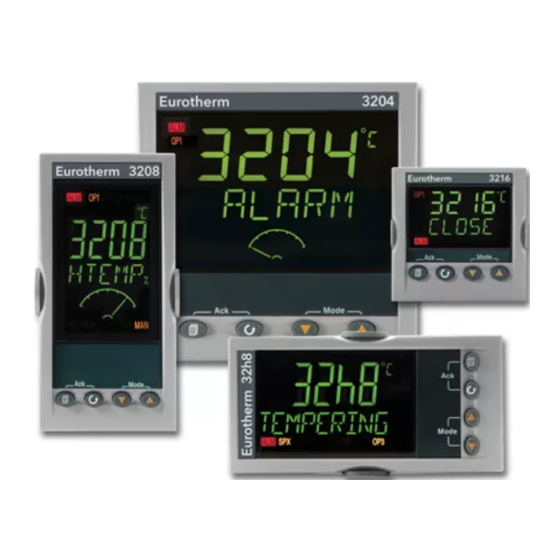
3200 Series 1. Installation and Basic Operation What Instrument Do I Have? Thank you for choosing this 3200 series Temperature Dimensions Controller/Programmer. General views of the controllers are shown below The 3200 series provide precise temperature control of together with overall dimensions. industrial processes and is available in three standard 3216 DIN sizes:-... -
Page 8: Step 1: Installation
3200 Series Step 1: Installation 1.4.2 Panel Cut Out Sizes This instrument is intended for permanent installation, for indoor use only, and enclosed in an electrical panel 45 mm - 0.0 + 0.6 Select a location which is subject to minimum vibrations Model 3216 Model 32h8 1.77 in... -
Page 9: Order Code
3200 Series Order Code 3216 3208 32h8 3204 1. Model No. 4. Outputs 1, 2 and 3 3208/H8/04 7. Fascia colour/type 1/16 DIN size 3216 Green 1/8 DIN size 3208 Silver vertical Wash down fascia 1/8 DIN horizontal 32h8 (not 32h8/04) 1/4 DIN size 3204 2. -
Page 10: Step 2: Wiring
3200 Series 2. Step 2: Wiring Terminal Layout 3216 Controller Ensure that you have the correct supply for your indicator Check order code of the controller supplied Input/Output 1 Output 4 (AA Relay) Output 2 Sensor A(+) Input Input 2.49Ω B(-) Line Supply 100 to 240Vac 48 to 62Hz... -
Page 11: Terminal Layout 32H8 Controllers
3200 Series Terminal Layout 32h8 Controllers Output Input/ Ensure that you have the correct Output 1 supply for your indicator Check order code of the controller supplied Output in B 24V Transmitter Supply Line Supply 100 to 240Vac 48 to NO C 62 Hz Low Voltage Supply 24Vac/dc... -
Page 12: Wire Sizes
3200 Series Wire Sizes 2.6.3 Linear Input (mA or mV) The screw terminals accept wire sizes from 0.5 to 1.5 mm 2.49Ω (16 to 22AWG). Hinged covers prevent hands or metal making accidental contact with live wires. The rear mA / mV input terminal screws should be tightened to 0.4Nm (3.5lb in). -
Page 13: Input/Output 1 & Output 2
3200 Series Input/Output 1 & Output 2 Remote Setpoint Input These outputs can be logic (SSR drive), or relay, or mA • There are two inputs; 4- dc. In addition the logic output 1 can be used as a 20mA and 0-10 Volts which 0-10 Volts contact closure input. -
Page 14: General Note About Relays And Inductive Loads
3200 Series 2.11 General Note About Relays and 2.13 Current Transformer Inductive Loads The current transformer input is an optional input in all 3200 series controllers. High voltage transients may occur when switching inductive loads such as some contactors or solenoid ☺... -
Page 15: Digital Communications
3200 Series 2.15 Digital Communications 2.15.1.1 EIA422 Connections (3216 only) Optional. Digital communications uses the Modbus protocol. The interface may be ordered as EIA232 or EIA485 (2-wire). In 3216 controllers only, EIA422 (4-wire) is available as option 6XX. ☺ Digital communications is not available if Remote Com Rx Setpoint is fitted ☺... -
Page 16: Controller Power Supply
3200 Series 2.16 Controller Power Supply 2.17 Example Heat/Cool Wiring Diagram Before connecting the instrument to the power line, This example shows a heat/cool temperature controller make sure that the line voltage corresponds to the where the heater control uses a SSR and the cooling description on the identification label. -
Page 17: Safety And Emc Information
3200 Series damage by electrostatic discharge from someone 3. Safety and EMC Information handling the controller. To avoid this, before handling This controller is intended for industrial temperature and the unplugged controller discharge yourself to ground. process control applications when it will meet the Cleaning requirements of the European Directives on Safety and Do not use water or water based products to clean labels... - Page 18 To ensure compliance with the European EMC directive certain installation precautions are necessary as follows: Conductive pollution • For general guidance refer to Eurotherm Controls Electrically conductive pollution must be excluded from EMC Installation Guide, HA025464. the cabinet in which the controller is mounted. For example, carbon dust is a form of electrically conductive •...
-
Page 19: Switch On
3200 Series Adjust these as follows:-. Switch On Press any button The characters will change to ‘-‘, The way in which the controller starts up depends on the first one flashing. factors described below in sections 4.1, 4.2 and 4.3. Press to change the flashing character to New Controller... -
Page 20: To Re-Enter Quick Code Mode
3200 Series SET 2 1 WRDT Input CT Scaling Digital Input A Digital Input B (2) Output 3 (2) Lower Display Unconfigured Unconfigured Unconfigured Setpoint (std) 10 Amps Alarm acknowledge PID heating or motor valve open (3) Output 25 Amps Manual select PID cooling or motor valve close (3) Time remaining... -
Page 21: Front Panel Layout
3200 Series Front Panel Layout Measured Temperature (or Process Value ‘PV’) ALM Alarm active (Red) OP1 lit when output 1 is ON (normally heating) Target Temperature OP2 lit when output 2 is ON (normally cooling ) (Setpoint ‘SP’) OP3 lit when output 3 is ON Meter (3208 and 3204 only) –configurable as: - Off OP4 lit when output 4 relay is ON (normally alarm) -
Page 22: Auto, Manual And Off Mode
3200 Series 4.4.4 Auto, Manual and Off Mode 4.4.5 To Select Auto, Manual or Off Mode Press and hold (Mode) together for The controller can be put into Auto, Manual or Off more than 1 second. mode – see next section. This can only be accessed from the HOME display. -
Page 23: Level 1 Operator Parameters
3200 Series 4.4.6 Level 1 Operator Parameters 5. Operator Level 2 A minimal list of parameters are available in operator Level 2 provides access to additional parameters. Level 1 which is designed for day to day operation. Access to these is protected by a security code. Access to these parameters is not protected by a pass code. - Page 24 3200 Series Mnemonic Scrolling Display and description Range WKG.SP WORKING SETPOINT is the active setpoint value and appears when the SP.HI to SP.LO controller is in Manual mode. It may be derived from SP1 or SP2, or, if the controller is ramping (see SP.RAT), it is the current ramp value. WRK.OP WORKING OUTPUT is the output from the controller expressed as a percentage Read only value...
- Page 25 3200 Series Mnemonic Scrolling Display and description Range SS.SP SOFT START SETPOINT This parameter only appears if the timer configuration Between SP.HI and SP.LO is set to sfst (Softstart). It sets the threshold value below which the power is limited DWELL SET TIME DURATION - Sets the dwell timing period.
- Page 26 3200 Series Mnemonic Scrolling Display and description Range turning off and turning on when ON/OFF control is used. Only appears if Default 1.0 channel 2 (cooling) control action is On/Off D.BAND CHANNEL 2 DEADBAND adjusts a zone between heating and cooling outputs OFF or 0.1 to 100.0% of the when neither output is on.
-
Page 27: Timer Operation
3200 Series Timer Operation An internal timer can be configured to operate in one of four different modes. The mode is configured in Level 2 by the ‘TM.CFG’ (timer configuration) parameter. Each Timing Mode is described in the pages that follow. Operation Action Indication... -
Page 28: Dwell Timer
3200 Series Dwell Timer A dwell timer (‘TM.CFG’ = ‘DwEl’) is used to control a In the END state the behaviour is determined by the process at a fixed temperature for a defined period. parameter ‘END.T’ (End type): In reset the controller behaviour depends on the OFF: The heating and cooling is turned OFF (resets configuration of the END state parameter. -
Page 29: Soft Start Timer
3200 Series Soft Start Timer ‘TM.CFG’ = ‘ SS.St’ A Soft Start timer starts automatically on power up. It applies a power limit (‘SS.PWR’) until the temperature reaches a threshold value (‘SS.SP’) or the timer times-out after the dwell period (‘ ). -
Page 30: Programmer Servo Mode And Power Cycling
3200 Series 5.8.1 Programmer Servo Mode and Power Cycling The way in which the program starts when ‘Run’ is selected or after the power is turned off and on again, is determined by the SERVO MODE parameter, as follows:- SERVO MODE The program will start from the current setpoint value. -
Page 31: To Configure The Programmer
3200 Series 5.8.3 To Configure the Programmer Select Access Level 2 – see section 5. Operation Action Indication Notes Configure Press to select ‘TM.CFG’ the Timer as Press to ‘ProG’ Programmer Set the In this example the ramp rate and Press to select ‘TM.RES’... -
Page 32: Access To Further Parameters
3200 Series 6.1.2 Configuration Level 6. Access to Further Parameters This level makes available all parameters including the Parameters are available under different levels of operation parameters so that there is no need to switch security and are defined as Level 1 (Lev1), Level 2 between configuration and operation levels during (Lev2), Level 3 (Lev 3) and Configuration (Conf). -
Page 33: To Select Access Level 3 Or Configuration Level
3200 Series 6.1.3 To Select Access Level 3 or Configuration Level Do This The Display You Should See Additional Notes To Select Level 3 The display will pass from the current operating level, for example, Lev 1 to Lev 3 as the button is held down. Lev 3 From any display press and hold for more than 5 seconds... -
Page 34: Parameter Lists
3200 Series Parameter lists 6.2.3 How Parameters are Displayed As shown above. whenever a parameter is selected it is Parameters are organised in lists. The top of the list displayed as a mnemonic, of four or five characters, for shows the list header only. The name of the list header example ‘A1.TYP’. -
Page 35: Navigation Diagram
3200 Series Navigation Diagram The diagram below shows the all list headings available in configuration level for 3216 controllers. The parameters in a list are shown in tables in the following sections of this manual together with explanations of their meanings and possible use. -
Page 36: Access Parameters
All alarms off in standby interlock a process. P a s s . c FEATURE PASSCODE To select chargeable features Contact Eurotherm. Note 5 Conf FEATURE PASSCODE To select chargeable features Conf P a s s . 2... - Page 37 ‘Pass2’ is read Note 4 only and is required to provide Eurotherm with the current instrument features. You will be given a Meter Configuration numeric code to enter as the new ‘PassC’ parameter.
-
Page 38: Controller Block Diagram
3200 Series 7. Controller Block Diagram The block diagram shows the simple building blocks which make up the controller. Each block has a list of parameters headed by a list name. For example the ‘Input List’ contains parameters which define the input type. The quick start code automatically sets the parameters to match the hardware. -
Page 39: Temperature (Or Process) Input
3200 Series 8. Temperature (or Process) Input Parameters in the input list configure the input to match your sensor. These parameters provide the following features:- Input Type and Thermocouple (TC) and 3-wire resistance thermometer (RTD) temperature detectors linearisation Linear input (-10 to +80mV). 0-10V using external voltage divider. mA assumes a 2.49Ω external shunt. -
Page 40: Input Types And Ranges
3200 Series INPUT LIST I N P U T Name Scrolling Display Parameter Description Value Default Access Level m v . i n MILLIVOLT Millivolts measured at the rear xx.xx mV - read only Conf INPUT VALUE PV Input terminals L3 R/O R c . -
Page 41: Operation Of Sensor Break
3200 Series 8.1.2 Operation of Sensor Break Sensor break type (SB.TYP) can be set to operate in three different modes:- Latching SB.TYP = Off Type of Output Output in Sensor Break Alarm State For heat + cool, OP.HI and OP.LO can be set OP.HI (100%) No alarm indication will be displayed between +100%... -
Page 42: Pv Offset
3200 Series PV Input Scaling PV Offset Input scaling applies to the linear mV input range only. All ranges of the controller have been calibrated against This is set by configuring the INPUT TYPE parameter to traceable reference standards. This means that if the mV and has an input range of –10 to 80mV. -
Page 43: Input/Output
3200 Series 9. Input/Output This section refers to:- • Digital Inputs Current Transformer Input • • Relay/Logic Outputs. The availability of these is shown in the following table:- Name Availability Output Input Output Function I/O Sense Beacon Terminal (lit when active) 3216 3208... -
Page 44: Input/Output Parameters
3200 Series Input/Output Parameters 9.1.1 Input/Output 1 List (IO-1) May be configured as relay, logic or DC output or to accept a digital input from external switch contacts. Connections are made to terminals 1A and 1B. OP1 beacon is operated from the IO-1 channel when it is configured as an output. INPUT/OUTPUT LIST 1 ‘I O -1 ’... - Page 45 3200 Series INPUT/OUTPUT LIST 1 ‘I O -1 ’ Name Scrolling Display Parameter Description Value Default Access Level 1 . P L S OUTPUT 1 Minimum output on/off 0.0 to Auto or 1.0 to 150.0 seconds 5.0 sec Conf MINIMUM PULSE time.
-
Page 46: Remote Digital Setpoint Select And Remote Fail
3200 Series 9.1.6 Example: To Configure IO-1 Relay to 9.1.2 Remote Digital Setpoint Select and Operate on Alarms 1 and 2:- Remote Fail These parameters were added in software version 1.11, Do This Display Additional Notes and subsequent versions, and are associated with the From any Scrolling display retransmission of remote setpoint through master... -
Page 47: Output List 2 (Op-2)
3200 Series 9.1.7 Output List 2 (OP-2) This is an optional normally open relay or logic output and is available on terminals 2A and 2B. The way in which this output operates is determined by parameters in the OP- 2 List. OP2 beacon is operated from this output channel. OUTPUT LIST 2 ‘op-2’... -
Page 48: Output List 3 (Op-3)
3200 Series 9.1.8 Output List 3 (OP-3) This is an optional normally open relay or 0-20mA dc output and is available on terminals 3A and 3B on 3208 and 3204 only. The way in which this output operates is determined by parameters in the OP- 3 List. OP3 beacon is operated from this output channel. -
Page 49: Aa Relay (Aa) (Output 4)
3200 Series 9.1.9 AA Relay (AA) (Output 4) This is a changeover relay and is optionally available in 3200 controllers. Connections are made to terminals AA, AB, and AC. The way in which this relay operates is determined by parameters in the AA List. OP4 beacon is operated from the AA relay output channel. -
Page 50: Digital Input Parameters
3200 Series 9.1.10 Digital Input Parameters Digital Input A. This is an optional input wired to terminals C and LA. The input is typically from a voltage free contact, which can be configured to operate a number of functions as determined by parameters in the LA List. ☺... -
Page 51: Current Transformer Input Parameters
3200 Series Current Transformer Input Parameters This is optional on 3200 controllers and can measure, via an external current transformer, the current flowing through the electrical load when the heat output is ‘on’ (load current) and also when it is ‘off’ (leakage current). ☺... -
Page 52: Setpoint Generator
3200 Series 10. Setpoint Generator Setpoint High and low limits can be pre-set to limits prevent inadvertent adjustment of the The setpoint generator provides the target value at which setpoint beyond that allowable for the it is required to control the process. It is shown in the process controller block diagram, Section 7. -
Page 53: Example: To Set Ramp Rate
3200 Series 10.2 Example: To Set Ramp Rate This is available in Level 3. Do This The Display You Additional Notes Should See Press as many times as necessary to select ‘SETPOINT LIST’ This step can be repeated for the lower setpoint limit Press as many times as necessary 73.00... -
Page 54: Control
3200 Series 11.2 Tuning 11. Control In tuning, you match the characteristics (PID Parameters in this section allow the control loop to be parameters) of the controller to those of the process set up for optimum control conditions. An example of being controlled in order to obtain good control. -
Page 55: How To Tune
3200 Series 11.2.2 How To Tune 11.2.4 Manual Tuning Set the setpoint to the value at which you will If for any reason automatic tuning gives unsatisfactory normally operate the process. results, you can tune the controller manually. There are a number of standard methods for manual tuning. -
Page 56: Integral Action And Manual Reset
3200 Series 11.3 Integral Action and Manual Reset 11.8 Loop Break In a full three-term controller (that is, a PID controller), The loop is considered to be broken if the PV does not the integral term automatically removes steady state respond to a change in the output. -
Page 57: Control Parameters
3200 Series 11.10 Control Parameters The following table shows the parameters available. CONTROL LIST ‘CTRL’ Parameter Parameter Description Value Default Access Name Level (Scrolling Display) C T R L . H HEATING TYPE As order Conf code Selects the channel 1 control Heating off algorithm. - Page 58 3200 Series CONTROL LIST ‘CTRL’ Parameter Parameter Description Value Default Access Name Level (Scrolling Display) O P . L O OUTPUT LOW +100.0% 0.0 (heat only) Adjust to limit the maximum cooling power applied to the process or to -100 apply a minimum heating power (cool) M T R .
-
Page 59: Auto-Tune Configures R2G
3200 Series 11.11 Auto-tune Configures R2G In a system which controls both heating and cooling the parameter R2G sets the cooling proportional band to compensate for differences between the power available to heat, and that available to cool a process, see section 11.4. There are certain load conditions where auto-tune may set an incorrect value for R2G. -
Page 60: Example: To Configure Heating And Cooling
3200 Series 11.12 Example: To Configure Heating and Cooling Enter configuration level as described. Then:- Do This The Display You Additional Notes Should See Press as many times as necessary to select ‘C T R L ’ Heating Type choices are:- Press to scroll to ‘C T R L H ’... -
Page 61: Effect Of Control Action, Hysteresis And Deadband
3200 Series 11.12.1 Effect of Control Action, Hysteresis and Deadband For temperature control ‘CONTROL ACTION’ will be set to ‘ ’. For a PID controller this means that the heater power decreases as the PV increases. For an on/off controller output 1 (usually heat) will be on (100%) when PV is below the setpoint and output 2 (usually cool) will be on when PV is above the setpoint Hysteresis applies to on/off control only. -
Page 62: Alarms
3200 Series 12. Alarms Alarms are used to alert an operator when a pre-set level has been exceeded. They are indicated by a scrolling message on the display and the red ALM beacon. They may also switch an output– usually a relay (see section 12.1.1) – to allow external devices to be operated when an alarm occurs. - Page 63 3200 Series Hysteresis Hysteresis is the difference between the point at which the alarm switches ‘ON’ and the point at which it switches ‘OFF’. It is used to provide a definite indication of the alarm condition and to prevent alarm relay chatter.
-
Page 64: Alarm Relay Output
A typical default message will show the source of the alarm followed by the type of alarm. For example, ‘ALARM 1 FULL SCALE HIGH’ • Using Eurotherm iTools configuration package, it is also possible to download customised alarm messages. An example might be, ‘PROCESS TOO HOT’. -
Page 65: Behaviour Of Alarms After A Power Cycle
3200 Series 12.2 Behaviour of Alarms After a Power 12.2.2 Example 2 Cycle Alarm configured as Absolute Low; Blocking: Manual Latching The response of an alarm after a power cycle depends upon the latching type, whether it has been configured Power Power Power... -
Page 66: Alarm Parameters
3200 Series 12.3 Alarm Parameters Four alarms are available. Parameters do not appear if the Alarm Type = None. The following table shows the parameters to set up and configure alarms. ALARM LIST ‘ALARM’ Name Scrolling Display Parameter Description Value Default Access Level... -
Page 67: Example: To Configure Alarm 1
3200 Series 12.3.1 Example: To Configure Alarm 1 Enter configuration level as described. Then:- Do This The Display You Additional Notes Should See Press as many times as necessary to select ‘ALARM’ Alarm Type choices are:- Press to select ‘A1.TYP’ Alarm not configured none Full Scale High... -
Page 68: Diagnostic Alarms
3200 Series 12.4 Diagnostic Alarms Diagnostic alarms indicate a possible fault within the controller or connected devices. Display shows What it means What to do about it E.Conf A change made to a parameter takes a finite time to Enter configuration mode then return to the be entered. -
Page 69: Timer/Programmer
3200 Series 13. Timer/Programmer A timer can be configured to operate in one of four different modes. These can be selected in Level 3 or configuration level as:- Dwell timer Delay timer Soft start timer Programmer – this is an orderable option Operation of the timer has been described in section 5. - Page 70 3200 Series TIMER LIST ‘t i m e r ’’ Name Scrolling Parameter Description Value Default Access Display Level Starts at SP1 (or SP2). sp.rb The program will continue to run from the original setpoint value at the last ramp rate. Starts at the current Process pv.rb value.
-
Page 71: Programmer
3200 Series 13.2 Programmer Model function CP is a controller which also contains a four segment setpoint programmer where each segment consists of a controlled rate ramp to a target setpoint followed by a dwell at that setpoint. These values can be set by the user. The program profile is shown in the diagram below. -
Page 72: Run/End Digital Outputs
3200 Series 13.2.2 Run/End Digital Outputs Digital outputs (normally relay) may be made to operate while the program is in Run mode or End mode, as shown in the diagram in section 13.2. These outputs are set up in configuration level by selecting the appropriate output parameter list - IO-1, OP-2, OP-3, or AA and assigning the parameter ‘PrG.E’... -
Page 73: To Configure The Programmer
3200 Series 13.2.4 To Configure the Programmer The programmer can be configured in Level 2 as explained in section 4. The Event outputs, however, can only be configured in Level 3 or Configuration level as follows:- Select Access Level 3 or Configuration level as described in section 6.1.3. Operation Action Display View... -
Page 74: Example: To Configure A Dwell Timer As A Simple Two Step Programmer
3200 Series 13.3 Example: To Configure a Dwell Timer as a Simple Two Step Programmer If the instrument has been ordered as controller only, it is still possible to configure a simple ramp/dwell; ramp/dwell programmer. This example assumes a hardware configuration as follows:- Output 2 Heat output relay I/O 1... - Page 75 3200 Series Select the AA To configure the AA relay timer run Press as many times as necessary to relay output list digital output signal select ‘A A ’ header Scrolling display ‘a a r e l a y ’ Set the output Scrolling display ‘o u t p u t 4 10.
- Page 76 3200 Series Assume the following settings SP1 = 70 End.T = SP2 = 20 Ramp Rate (SP.RAT) = 20 C/min The threshold value behaves like a holdback value and can be turned off. A digital output can be configured to operate an external buzzer, or other form of indication, to alert the operator to the end of the process.
-
Page 77: Recipe
3200 Series 14. Recipe A recipe can take a snapshot of the current values and store these into a recipe number. There are five recipes available, which can store a range of parameter values for different processes. The list of parameters is shown in section 14.3.1. -
Page 78: To Select A Recipe To Run
3200 Series 14.3 To Select a Recipe to Run Do This The Display You Should See Additional Notes Scrolling display R E C I P E L I S T Press as many times as necessary r e c i p to select ‘R E C I P ’... -
Page 79: Digital Communications
EIA485 (2-wire) To use EIA485, buffer the EIA232 port of the PC with a Digital Communications (or ‘comms’ for short) allows suitable EIA232/EIA485 converter. The Eurotherm the controller to communicate with a PC or a Controls KD485 Communications Adapter unit is networked computer system. -
Page 80: Digital Communications Parameters
3200 Series 15.2 Digital Communications Parameters The following table shows the parameters available. DIGITAL COMMUNICATIONS LIST ‘comms’ Name Scrolling Parameter Description Value Default Access Display Level MODULE Comms identity No module fitted As order Conf none IDENTITY code L3 R/O r232 RS 232 Modbus interface EIA485 Modbus interface... -
Page 81: Broadcast Communications
EIA232 writes. Note that in common with many third party EIA232 lower cost units, the Eurotherm 2200 series and the 3200 series prior to version V1.10 do not accept continuous writes to the temperature setpoint. Damage to the internal non-volatile memory could result from the use of this function. -
Page 82: Example: To Set Up Instrument Address
It is possible to read floating point data in a native 32 bit IEEE format. This is described in the Eurotherm Series 2000 Communications Handbook (HA026230), Chapter 7. For time data, for example, the length of a dwell, the integer representation depends on the resolution. -
Page 83: Parameter Modbus Addresses
3200 Series 15.5 Parameter Modbus Addresses Parameter Parameter Name Modbus Address Mnemonic Decimal PV.IN PV (Temperature) Input Value (see also Modbus address 203 which allows writes over Modbus to this variable). TG.SP Target Setpoint. NB – do not write continuously changing values to this variable. The memory technology used in this product has a limited (100,000) number of write cycles. - Page 84 3200 Series Parameter Parameter Name Modbus Address Mnemonic Decimal A2.HYS Alarm 2 Hysteresis A3.HYS Alarm 3 Hysteresis A4.HYS Alarm 4 Hysteresis StAt Instrument Status. This is a bitmap: B0 – Alarm 1 Status B1 – Alarm 2 Status B2 – Alarm 3 Status B3 –...
- Page 85 3200 Series Parameter Parameter Name Modbus Address Mnemonic Decimal Instrument version number. Should be read as a hexadecimal number, for example a value of 0111 hex is instrument V1.11 SP.HI Setpoint High Limit SP.LO Setpoint Low Limit Instrument type code. ADDR Instrument Comms Address PV.OFS...
- Page 86 3200 Series Parameter Parameter Name Modbus Address Mnemonic Decimal 1 – Mins:Secs SS.SP Soft Start Setpoint SS.PWR Soft Start Power Limit DWELL Requested Timer Duration T.ELAP Elapsed Time T.REMN Time Remaining THRES Timer Start threshold End.T Timer End Type 0 – Off 1 –...
- Page 87 3200 Series Parameter Parameter Name Modbus Address Mnemonic Decimal UNITS 1 – Ramp per Hour 2 – Ramp per Second Meter (3208/3204 Only). Ammeter configuration 0 – No ammeter 1 – Heat Output (0-100%) 2 – Cool Output (0-100% cooling) 3 –...
- Page 88 3200 Series Parameter Parameter Name Modbus Address Mnemonic Decimal 2 – Latching Sensor Break Customer ID – May be set to any value between 0-9999 for identification of instruments in applications. Not used by the instrument itself. PHASE Calibration Phase 0 –...
- Page 89 3200 Series Parameter Parameter Name Modbus Address Mnemonic Decimal 3 – R Type Thermocouple 4 – B Type Thermocouple 5 – N Type Thermocouple 6 – T Type Thermocouple 7 – S Type Thermocouple 8 – RTD 9 – millivolt 10 –...
- Page 90 3200 Series Parameter Parameter Name Modbus Address Mnemonic Decimal BAUD Baud Rate 12548 0 – 9600 1 – 19200 2 – 4800 3 – 2400 4 – 1200 PRTY Parity setting 12549 0 – None 1 – Even 2 – Odd DELAY RX/TX Delay –...
- Page 91 3200 Series Parameter Parameter Name Modbus Address Mnemonic Decimal 10 – DC Output no function 11 – DC Output Heat 12 – DC Output Cool 13 – DC Output WSP retransmission 14 – DC Output PV retransmission 15 – DC Output OP retransmission 1.RNG IO Channel 1 DC Output Range 12676...
- Page 92 3200 Series Parameter Parameter Name Modbus Address Mnemonic Decimal As IO Channel 1 Source A (Modbus address 12678) 2.SRC.D Output 2 source D 12745 As IO Channel 1 Source A (Modbus address 12678) 2.SENS Output 2 Polarity (0 = Normal, 1 = Inverted) 12746 2.PLS Output 2 Time proportioning Output minimum pulse time...
-
Page 93: Calibration
3200 Series 16.1.2 To Check mV Input Calibration 16. Calibration The controller is calibrated during manufacture using The input may have been configured for a process input traceable standards for every input range. It is, of mV, Volts or mA and scaled in Level 3 as described in therefore, not necessary to calibrate the controller when section 8.3. -
Page 94: To Check Rtd Input Calibration
3200 Series 16.1.4 To Check RTD Input Calibration 16.2 Offsets Connect a decade box with total resistance lower than The process value can be offset to take into account 1K and resolution to two decimal places in place of the known errors within the process. -
Page 95: To Apply A Two Point Offset
3200 Series 16.2.2 To Apply a Two Point Offset Assume the instrument is set up (as described in section 8.3.1) to display 0.0 for an input of 4.00mV and 500.0 for an input of 20.00mV. Assume that a particular sensor in use has known errors such that the instrument is required to read 8.0 for an input of 4.00mV and 490.0 for an input of 20.00mV. -
Page 96: Input Calibration
3200 Series 16.3 Input Calibration If the calibration is not within the specified accuracy follow the procedures in this section:- In 3200 series instruments, inputs which can be calibrated are:- mV Input. This is a linear 80mV range calibrated at two fixed points. This should always be done before calibrating •... -
Page 97: To Calibrate Thermocouple Input
3200 Series 16.3.2 To Calibrate Thermocouple Input Thermocouples are calibrated, firstly, by following the previous procedure for the mV ranges, then calibrating the CJC. Connect a mV source as described in section 16.1.3. Set the mV source to ‘internal compensation’ for the thermocouple in use and set the output for 0mV. -
Page 98: To Calibrate Rtd Input
3200 Series 16.3.3 To Calibrate RTD Input The two points at which the RTD range is calibrated are 150.00Ω and 400.00Ω. Before starting RTD calibration: • A decade box with total resistance lower than 1K must be connected in place of the RTD as indicated on the connection diagram in section 16.1.4 before the instrument is powered up. -
Page 99: To Calibrate Ma Outputs
3200 Series 16.3.4 To Calibrate mA Outputs I/O1, Output 2 and/or Output 3 may be supplied as mA outputs. The outputs may be adjusted as follows:- Connect an ammeter to the output – terminals 1A/1B, 2A/2B or 3A/3B as appropriate. Controller 2.00 A +ve... -
Page 100: To Calibrate Remote Setpoint Input
3200 Series 16.3.5 To Calibrate Remote Setpoint Input Current Controller HD Connect a milli amp source to terminals HD and HE as shown. Source Copper cable Select Conf Level as described in section 6.1.3, then:- Operation Do This Display View Additional Notes Select the Calibration Scrolling display ‘... -
Page 101: Ct Calibration
3200 Series 16.3.6 CT Calibration Controller To calibrate the current transformer input, connect the current transformer 70mA dc to terminals CT and C. Source Then in configuration level Operation Do This Display View Additional Notes Select the current transformer Scrolling display From the ‘C A L ’... -
Page 102: Calibration Parameters
3200 Series 16.4 Calibration Parameters The following table gives the parameters available in the Calibration List. The User Calibration is available in Level 3 only and is used to calibrate ‘Offset’ see section 8.2. CALIBRATION PARAMETER LIST ‘cAL’ Name Scrolling Parameter Value Default... -
Page 103: Configuration Using Itools
If the build of your instrument is a non-standard, it may controller. be necessary for you to download the IDM from the Eurotherm web site. The file will be of the format id32i_v107.exe, where id 32i is the instrument and V--- is the software version number of the instrument. -
Page 104: Starting Itools
3200 Series 17.3 Starting iTools Open iTools and, with the controller connected, press on the iTools menu bar. iTools will search the communications ports and TCPIP connections for recognisable instruments. Controllers connected with the configuration clip (CPI), will be found at address 255 regardless of the address configured in the controller. When the instrument is detected a screen view similar to the one shown below will be displayed. -
Page 105: Starting The Wizard
3200 Series 17.4 Starting the Wizard From the opening view shown in section 17.3, press The controller will be set to configuration level. Since it will not operate the process in configuration level a warning message appears. When this is accepted the Wizard start up screen is shown:- Select a tab to configure a function. -
Page 106: To Configure The Input
3200 Series 17.5 To configure the Input 17.5.1 Example 1 - Using the Wizard Select the ‘Input’ tab To configure the A ‘help’ text is input type, open shown to the the drop down right of the box and select wizard. -
Page 107: To Configure Alarms
3200 Series 17.6 To Configure Alarms 17.6.1 Example 1: Using the Wizard Up to four alarms are available in 3200 series controllers. Set the type of alarm, latching mode, blocking, threshold and hysteresis from drop down menus. Help text is shown together with a pictorial representation of the alarm operation. 17.6.2 Example 2: Using the Browser View 1. -
Page 108: To Customise Messages
3200 Series 17.7 To Customise Messages The message which scrolls across the controller display during normal operation may be customised. 17.7.1 Example 1: Using the Wizard Select the ‘Messages’ tab. Display the message ‘OUT OF CONTROL’ if both Alarm 1 and Alarm 2 are active. Operation Action Indication... -
Page 109: Example 2: Using The Browser View
3200 Series Note 1:- Mask allows any combination of parameters in the above bitmap field to activate the custom message. The table below shows how this operates for the four alarm fields. Value Bitmap Parameter (Alarm) Value Bitmap Parameter (Alarm) active Other parameters active can be added by... -
Page 110: Example 3: Inverted Status Word
3200 Series 17.7.3 Example 3: Inverted Status Word The Inverted Status Word is available in firmware versions 2.11+. It is used to generate a message when a bit in a status word is not true. For example, it may be applied to an alarm or event to indicate that the process is operating normally. The example below continues from the previous example and adds the message PROCESS OK on the controller when the Alarm 1 condition is not true. -
Page 111: Example 4: Display The Message 'Out Of Control' If Both Alarm 1 And Alarm 2 Are Active
3200 Series 17.7.4 Example 4: Display the message ‘OUT OF CONTROL’ if both Alarm 1 and Alarm 2 are active. Operation Action Indication Add a Right click where the parameter parameter is required Select ‘Insert Item’ Choose the parameter from the pop up box eg ‘STATUS InstStatus’... -
Page 112: To Promote Parameters
3200 Series 17.8 To Promote Parameters The list of parameters which are available in operator levels 1 or 2 can be changed using the ‘Promote’ wizard. Access can be set to Read Only or Read/Write. 17.8.1 Example 1: Using the Wizard Select ‘Promote’... -
Page 113: Example 2: Using The Browser View
3200 Series 17.8.2 Example 2: Using the Browser view In this example the parameter ‘OP2.Sense’ is added to the to the Level 2 list. Press and select the Memory Table tab Select the ‘Promote Parameters’ tab Highlight the position where you want the new parameter to be placed Press button and from the pop up window select the required parameter. -
Page 114: To Load A Special Linearisation Table
Example: Using the Browser view Press Select the linearisation table to be loaded from files with the extension .mtb. Linearisation files for different sensor types are supplied with iTools and may be found in Program Files Eurotherm iTools Linearisations Thermocouple etc. -
Page 115: To Set Up Recipes
3200 Series 17.10 To Set up Recipes A recipe can store up to 38 parameters, as listed in section 14.3.1. Up to five recipes are available in 3200 series controllers, as described in section 14. 17.10.1 Example 1: Using the Browser view Set Two Different Alarm Thresholds and Store in Recipes 1 and 2 Set an alarm threshold - see example 17.6.2. -
Page 116: Example 2: Using The Wizard
3200 Series 17.10.2 Example 2: Using the Wizard Select the ‘Recipe’ tab 17.10.2.1 Recipe Definition Select ‘Recipe Definition’ tab to display the default parameters available to be stored in recipe. Double click on the parameter in the ‘Wired From’ column, a pop up allows you to delete or change to a different parameter. Part No HA028651 Issue 7.0 Apr-09... -
Page 117: Editing Recipe Values
3200 Series 17.10.2.2 Editing Recipe Values Select any one of the Recipe01 to 05 tabs. It is necessary to set the values of all parameters. Start with the first followed by all other parameters. To download the new values, press Next> or select any other tab. There is a delay whilst the recipe updates. To ensure the controller accepts the new recipe values, select another recipe in the controller itself, then go back to the recipe in which the changes were made. -
Page 118: Summary
3200 Series 17.11 Summary The terminal connections for the functions which have been configured together with a description of each function. 17.11.1 Example 1: Using the Wizard Press ‘Summary’ tab. 17.11.2 Example 2: Using the browser view. Press A summary of the features configured may be selected using the ‘Summary’... -
Page 119: Cloning
3200 Series 17.12 Cloning The cloning feature allows the configuration and parameter settings of one instrument to be copied into another. Alternatively a configuration may be saved to file and this used to download to connected instruments. The feature allows new instruments to be rapidly set up using a known reference source or standard instrument. Every parameter and parameter value is downloaded to the new instrument which means that if the new instrument is used as a replacement it will contain exactly the same information as the original. -
Page 120: Appendix A Technical Specification
3200 Series 18. Appendix A TECHNICAL SPECIFICATION Analogue Input Sample rate 4Hz (250mS) Calibration accuracy +0.25% of reading +1LSD Resolution <5, 0.5µV when using a 5 second filter Linearisation accuracy <0.1% of reading Input filter Off to 59.9 seconds Zero offset User adjustable over the full display range Thermocouple Types Refer to Sensor inputs and display ranges table... - Page 121 3200 Series Setpoint rate limit Off to 9999 degrees or display units per minute Tuning One-shot tune Automatic calculation of PID and overshoot inhibition parameters Alarms Types Full scale high or low. Deviation high, low, or band Modes Latching or non-latching. Normal or blocking action Up to four process alarms can be combined onto a single output Current Transformer Input Input current...
-
Page 122: Parameter Index
3200 Series Mnemonic Parameter Location 19. Parameter Index Description This is a list of parameters used in 3200 series A 1 . - - - ALARM 1 SETPOINT Alarm Parameters Section 12.3 controllers in alphabetical order together with the A1.BLK ALARM 1 BLOCKING Alarm Parameters Section 12.3 section in which they are to be found. - Page 123 3200 Series Mnemonic Parameter Location Mnemonic Parameter Location Description Description HC.ALM OVER CURRENT CT List Section 9.2 R A M P U SETPOINT RAMP Setpoint List Section 10.1 THRESHOLD UNITS HOME HOME DISPLAY See Access List R C . F T Filter time constant Modbus addresses section 15.5 Note 1...
- Page 124 3200 Series Part No HA028651 Issue 7.0 Apr-09...
-
Page 125: Index
3200 Series 20. Index 1.PLS................11, 42, 89, 120 Access Parameters .................34 Acknowledge ..............62, 83, 87, 88 1.SENS ................. 43, 44, 89, 120 ADDR ................24, 78, 80, 83, 120 1.SRC.A ..............42, 44, 72, 88, 120 Address ..................80, 81, 83 1.SRC.B ................ - Page 126 3200 Series DEC.P................... 37, 84, 120 t.HLd..................... 42, 48 DELAY ................. 78, 88, 120 T.REMN..............21, 23, 68, 84, 121 Dwell ..18, 22, 25, 26, 29, 67, 70, 71, 72, 73, 76, 83, 84, 86 t.res....................42, 48 t.rrS....................42, 48 ENT.T....................
- Page 127 3200 Series OUTPUT MINIMUM PULSE TIME ....... 45, 46, 47, 120 Input Type Output Power................82, 84, 88 RTD ......................38 Type mV ..10, 37, 38, 40, 87, 91, 92, 93, 94, 95, 96, 98, 100 Over/Under range..................37 INPUT TYPE ................37, 40, 121 PID ....17, 18, 23, 29, 35, 44, 52, 54, 55, 58, 59, 84, 118, 119 Input Type and linearisation ...............37 Power Supply................
- Page 128 3200 Series terminals ...8, 10, 13, 16, 38, 42, 45, 46, 47, 48, 60, 77, 79, 91, 97, Timer..2, 3, 17, 18, 19, 21, 22, 23, 25, 26, 27, 29, 35, 42, 45, 46, 98, 99 47, 48, 67, 69, 71, 72, 73, 76, 81, 82, 83, 84, 86, 87, 88, 106, Thermocouple .....
- Page 130 HA028651/7 (CN25274) Specification subject to change without notice. ©Eurotherm Limited. Invensys, Eurotherm, the Eurotherm logo, Chessell, EurothermSuite, Mini8, EPower, Eycon, Eyris and Wonderware are trademarks of Invensys plc, its subsidiaries and affiliates. All other brands may be trademarks of their respec-...
Need help?
Do you have a question about the 3100 and is the answer not in the manual?
Questions and answers