Sign In
Upload
Manuals
Brands
Eurotherm Manuals
Temperature Controller
3100
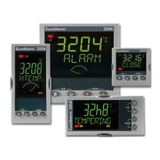
Eurotherm 3100 PID Temperature Controller Manuals
Manuals and User Guides for Eurotherm 3100 PID Temperature Controller. We have
1
Eurotherm 3100 PID Temperature Controller manual available for free PDF download: Engineering Manual
Eurotherm 3100 Engineering Manual (130 pages)
PID Temperature Controllers
Brand:
Eurotherm
| Category:
Temperature Controller
| Size: 3 MB
Table of Contents
Table of Contents
3
1 Installation and Basic Operation
7
What Instrument Do I Have
7
Unpacking Your Controller
7
Dimensions
7
Step 1: Installation
8
Panel Mounting the Controller
8
Panel Cut out Sizes
8
Recommended Minimum Spacing of Controllers
8
To Remove the Controller from Its Sleeve
8
Order Code
9
2 Step 2: Wiring
10
Terminal Layout 3216 Controller
10
Terminal Layout 32H8 Controllers
11
Terminal Layout 3208 and 3204 Controllers
11
Wire Sizes
12
Precautions
12
Sensor Input (Measuring Input)
12
Thermocouple Input
12
RTD Input
12
Linear Input (Ma or MV)
12
Two-Wire Transmitter Inputs
12
Input/Output 1 & Output 2
13
Relay Output (Form A, Normally Open)
13
Logic (SSR Drive) Output
13
DC Output
13
Triac Output
13
Logic Contact Closure Input (I/O 1 Only)
13
Remote Setpoint Input
13
Output 3
13
Output 4 (AA Relay)
13
General Note about Relays and Inductive Loads
14
Digital Inputs a & B
14
Current Transformer
14
Transmitter Power Supply
14
Digital Communications
15
EIA422 Connections (3216 Only)
15
Controller Power Supply
16
Example Heat/Cool Wiring Diagram
16
Example CT Wiring Diagram
16
3 Safety and EMC Information
17
Installation Safety Requirements
17
4 Switch on
19
New Controller
19
Quick Start Code
19
To Re-Enter Quick Code Mode
20
Pre-Configured Controller or Subsequent Starts
20
Front Panel Layout
21
To Set the Target Temperature
21
Alarms
21
Alarm Indication
21
Auto, Manual and off Mode
22
To Select Auto, Manual or off Mode
22
Level 1 Operator Parameters
23
5 Operator Level 2
23
To Enter Level 2
23
To Return to Level 1
23
Level 2 Parameters
23
Timer Operation
27
Dwell Timer
28
Delayed Timer
28
Soft Start Timer
29
Programmer
29
Programmer Servo Mode and Power Cycling
30
To Operate the Programmer
30
To Configure the Programmer
31
6 Access to Further Parameters
32
Level 3
32
Configuration Level
32
To Select Access Level 3 or Configuration Level
33
Parameter Lists
34
To Choose Parameter List Headers
34
To Locate a Parameter
34
How Parameters Are Displayed
34
To Change a Parameter Value
34
To Return to the HOME Display
34
Time out
34
Navigation Diagram
35
Access Parameters
36
7 Controller Block Diagram
38
8 Temperature (or Process) Input
39
Process Input Parameters
39
Input Types and Ranges
40
Operation of Sensor Break
41
PV Offset
42
Example: to Apply an Offset
42
PV Input Scaling
42
Example: to Scale a Linear Input
42
9 Input/Output
43
Input/Output Parameters
44
Input/Output 1 List (IO-1)
44
Remote Digital Setpoint Select and Remote Fail
46
Sense
46
Source
46
Power Fail
46
Example: to Configure IO-1 Relay to Operate on Alarms 1 and 2
46
Output List 2 (OP-2)
47
Output List 3 (OP-3)
48
AA Relay (AA) (Output 4)
49
Digital Input Parameters
50
Current Transformer Input Parameters
51
Analogue Representation of Current Alarms
51
10 Setpoint Generator
52
Setpoint Parameters
52
Example: to Set Ramp Rate
53
11 Control
54
PID Control
54
Tuning
54
Automatic Tuning
54
How to Tune
55
Calculation of the Cutback Values
55
Manual Tuning
55
Setting the Cutback Values
55
Integral Action and Manual Reset
56
Relative Cool Gain
56
Control Action
56
On/Off Control
56
Valve Position Control
56
Loop Break
56
Cooling Algorithm
56
Control Parameters
57
Auto-Tune Configures R2G
59
Example: to Configure Heating and Cooling
60
Effect of Control Action, Hysteresis and Deadband
61
12 Alarms
62
Types of Alarm
62
Alarm Relay Output
64
Alarm Indication
64
To Acknowledge an Alarm
64
Behaviour of Alarms after a Power Cycle
65
Example 1
65
Example 2
65
Example 3
65
Alarm Parameters
66
Example: to Configure Alarm 1
67
Diagnostic Alarms
68
Out of Range Indication
68
13 Timer/Programmer
69
Timer Parameters
69
Programmer
71
Threshold
71
Run/End Digital Outputs
72
Event Outputs
72
To Configure the Programmer
73
Example: to Configure a Dwell Timer as a Simple Two Step Programmer
74
14 Recipe
77
To Save Values in a Recipe
77
To Save Values in a Second Recipe
77
To Select a Recipe to Run
78
List of Default Recipe Parameters
78
15 Digital Communications
79
Digital Communications Wiring
79
Eia232
79
EIA485 (2-Wire)
79
Wiring EIA422 or 4-Wire EIA485
79
Digital Communications Parameters
80
Broadcast Communications
81
Broadcast Master Communications
81
Wiring Connections
81
Example: to Set up Instrument Address
82
Data Encoding
82
Parameter Modbus Addresses
83
16 Calibration
93
To Check Input Calibration
93
Precautions
93
To Check MV Input Calibration
93
To Check Thermocouple Input Calibration
93
To Check RTD Input Calibration
94
Offsets
94
Two Point Offset
94
To Apply a Two Point Offset
95
To Remove the Two Point Offset
95
Input Calibration
96
To Calibrate MV Input
96
To Calibrate Thermocouple Input
97
To Calibrate RTD Input
98
To Calibrate Ma Outputs
99
To Calibrate Remote Setpoint Input
100
CT Calibration
101
To Return to Factory Calibration
101
Calibration Parameters
102
17 Configuration Using Itools
103
Loading an IDM
103
Connecting a PC to the Controller
103
Using the H Communications Port
103
Configuration Clip
103
Starting Itools
104
Starting the Wizard
105
To Configure the Input
106
Example 1 - Using the Wizard
106
Example 2 - Using the Browser View
106
To Configure Alarms
107
Example 1: Using the Wizard
107
Example 2: Using the Browser View
107
To Customise Messages
108
Example 1: Using the Wizard
108
Example 2: Using the Browser View
109
Example 3: Inverted Status Word
110
Example 4: Display the Message 'OUT of CONTROL' if both Alarm 1 and Alarm 2 Are Active
111
To Promote Parameters
112
Example 1: Using the Wizard
112
Example 2: Using the Browser View
113
To Load a Special Linearisation Table
114
Example: Using the Browser View
114
To Set up Recipes
115
Example 1: Using the Browser View
115
Example 2: Using the Wizard
116
Recipe Definition
116
Editing Recipe Values
117
Recipe Names
117
Summary
118
Example 1: Using the Wizard
118
Example 2: Using the Browser View
118
Cloning
119
Save to File
119
To Clone a New Controller
119
18 Appendix A TECHNICAL SPECIFICATION
120
19 Parameter Index
122
20 Index
125
Advertisement
Advertisement
Related Products
Eurotherm 3116
Eurotherm 3116 PID
Eurotherm 3200
Eurotherm 316
Eurotherm Invensys 3216
Eurotherm 3204i
Eurotherm 32h8i
Eurotherm 3504
Eurotherm 3204
Eurotherm 32h8
Eurotherm Categories
Controller
Temperature Controller
Voice Recorder
Measuring Instruments
Media Converter
More Eurotherm Manuals
Login
Sign In
OR
Sign in with Facebook
Sign in with Google
Upload manual
Upload from disk
Upload from URL