
Subscribe to Our Youtube Channel
Related Manuals for Eurotherm 0216


Summary of Contents for Eurotherm 0216
- Page 1 PID CONTROLLERS PID CONTROLLERS PID CONTROLLERS PID CONTROLLERS PID CONTROLLERS USER MANUAL USER MANUAL USER MANUAL USER MANUAL USER MANUAL...
-
Page 2: Table Of Contents
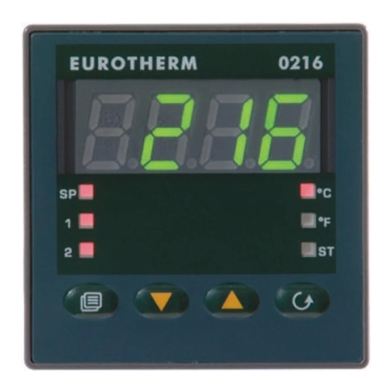
INDEX INDEX INDEX INDEX INDEX A . WHAT YOU NEED TO KNOW BEFORE YOU WHAT YOU NEED TO KNOW BEFORE YOU WHAT YOU NEED TO KNOW BEFORE YOU WHAT YOU NEED TO KNOW BEFORE YOU WHAT YOU NEED TO KNOW BEFORE YOU S T A R T S T A R T S T A R T .............. - Page 3 Home Screen Definition Home Screen Definition Home Screen Definition Home Screen Definition Model 0216 displays the measured value or the operating set point. When the timer is running, time remaining is displayed. LED “A” flashing indicates the timer is running, LED “B”...
- Page 4 CONFIGURATION ENTRY & EXIT CONFIGURATION ENTRY & EXIT CONFIGURATION ENTRY & EXIT CONFIGURATION ENTRY & EXIT CONFIGURATION ENTRY & EXIT DIRECT SETPOINT ENTRY DIRECT SETPOINT ENTRY DIRECT SETPOINT ENTRY DIRECT SETPOINT ENTRY DIRECT SETPOINT ENTRY See page 16 section 5.6 While viewing the normal display hold either the E n t r y E n t r y...
-
Page 5: S T A R T S T A R T S T A R T
DEFAULT CONFIGURATION DEFAULT CONFIGURATION TIMER CONTROL FROM FRONT TIMER CONTROL FROM FRONT DEFAULT CONFIGURATION DEFAULT CONFIGURATION DEFAULT CONFIGURATION TIMER CONTROL FROM FRONT TIMER CONTROL FROM FRONT TIMER CONTROL FROM FRONT PANEL KEYS PANEL KEYS See section B PANEL KEYS PANEL KEYS PANEL KEYS The instrument can be pre-loaded with factory See page 17 section 5.7... -
Page 6: Outline And Cut Out Dimensions
OUTLINE AND CUT OUT DIMENSIONS OUTLINE AND CUT OUT DIMENSIONS A . 1 A . 1 A . 1 OUTLINE AND CUT OUT DIMENSIONS OUTLINE AND CUT OUT DIMENSIONS OUTLINE AND CUT OUT DIMENSIONS 0216 0216 0216 0216 0216 0316 0316 0316... -
Page 7: Mounting Mounting
1. 1. 1. 1. 1. MOUNTING MOUNTING MOUNTING MOUNTING MOUNTING screws Select a mounting location where there is bracket minimum vibration and the ambient temperature gasket ranges between 0 and 50°C (32 and 122°F). panel The instrument can be mounted on a panel up to 15 mm thick with a square cutout of 45 x 45 mm. -
Page 8: Electrical Connections Electrical Connections
2. 2. 2. 2. 2. ELECTRICAL CONNECTIONS ELECTRICAL CONNECTIONS ELECTRICAL CONNECTIONS ELECTRICAL CONNECTIONS ELECTRICAL CONNECTIONS MEASURING INPUTS MEASURING INPUTS MEASURING INPUTS MEASURING INPUTS MEASURING INPUTS NOTE NOTE NOTE NOTE NOTE: Any external components (like zener barriers etc.) connected between sensor and input Connections are to be made with the instrument terminals may cause errors in measurement due housing installed in its proper location. - Page 9 RTD INPUT RTD INPUT RTD INPUT LOGIC INPUT LOGIC INPUT LOGIC INPUT RTD INPUT RTD INPUT LOGIC INPUT LOGIC INPUT Safety note: 1) Do not run logic input wiring together with power cables. 2) Use an external dry contact capable of switching 8 mA, 8 V DC.
- Page 10 RELAY OUTS RELAY OUTS RELAY OUTS Use copper conductors only. RELAY OUTS RELAY OUTS Do not run input wires together with power line cables. OUT 1 The following recommendations avoid serious problems which may occur it when using relay output to drive inductive loads. INDUCTIVE LOADS INDUCTIVE LOADS INDUCTIVE LOADS...
- Page 11 POWER LINE WIRING POWER LINE WIRING POWER LINE WIRING POWER LINE WIRING POWER LINE WIRING LOAD OPERATING (mA) (mF) VOLTAGE Power Line <40 0.047 260 V AC 100 V to 240 V AC (50/60Hz) <150 mA 260 V AC or 24 V AC/DC <0.5 0.33 260 V AC...
-
Page 12: Preliminary Hardware Preliminary Hardware Settings
3 . 3 . 3 . 3 . 3 . PRELIMINARY HARDWARE PRELIMINARY HARDWARE PRELIMINARY HARDWARE PRELIMINARY HARDWARE PRELIMINARY HARDWARE 4 . 4 . 4 . 4 . 4 . CONFIGURATION CONFIGURATION CONFIGURATION CONFIGURATION CONFIGURATION SETTINGS SETTINGS SETTINGS SETTINGS SETTINGS 4 . -
Page 13: Access To The Configuration Procedure
In the model 0316 the lower display will show Cnf, 4 RTD type Pt 100 -199 / +800 °C (0316) the upper OFF. In model 0216 OFF and CnF will -200 / +800 °C (0216) appear alternatively. 5 RTD type Pt 100 -19.9 / +99.9 °C... - Page 14 NOTE: NOTE: NOTE: When P1 has been changed, the P2 and NOTE: NOTE: Reverse Reverse Reverse Reverse Reverse Direct Direct Direct Direct Direct P10 parametrer will be forced to the minimum Input value of the selected range while the P3 parameter Input will be forced to the maximum value of the selected range .
- Page 15 P6 = Out 2 configuration P6 = Out 2 configuration P6 = Out 2 configuration P8 = Stand-by of the alarm 1 P8 = Stand-by of the alarm 1 P8 = Stand-by of the alarm 1 P6 = Out 2 configuration P6 = Out 2 configuration P8 = Stand-by of the alarm 1 P8 = Stand-by of the alarm 1...
- Page 16 0316: between P17 or P18 and 99.9% condition (the parameters from SP to t and model 0216: between P17 or P18 and 100.0% AL.1 – AL.2 are not subjected to the P17 - - - - - Proportional minimum band value...
- Page 17 H.L. minutes) L.L. = in band with manual reset model 0216: between 00.01 (1 second) and 2.00 (2 minutes). P24 = Alarm 2 action P24 = Alarm 2 action P24 = Alarm 2 action...
- Page 18 P27 – FEATURE FUNCTION P27 – FEATURE FUNCTION P27 – FEATURE FUNCTION Timer mode 2 [P27 = 3] Timer mode 2 [P27 = 3] Timer mode 2 [P27 = 3] P27 – FEATURE FUNCTION P27 – FEATURE FUNCTION Timer mode 2 [P27 = 3] Timer mode 2 [P27 = 3] 0 = None When the contact is closed, the instrument...
- Page 19 Timer mode 4 [P27 = 5] Timer mode 4 [P27 = 5] Timer mode 4 [P27 = 5] Timer mode 6 [P27 = 7] Timer mode 6 [P27 = 7] Timer mode 6 [P27 = 7] Timer mode 4 [P27 = 5] Timer mode 4 [P27 = 5] Timer mode 6 [P27 = 7] Timer mode 6 [P27 = 7]...
-
Page 20: Operative Mode Operative Mode
- Model 0316 displays the abbreviated name of the selected parameter on the lower display, on the upper it will display the selected value. - Model 0216 displays alternately the name of the parameter and its value: during the modification it displays only the value. -
Page 21: Smart Algorithm
5 . 2 5 . 2 5 . 2 SMART ALGORITHM SMART ALGORITHM SMART ALGORITHM SMART ALGORITHM 5 . 3 5 . 3 INHIBITION OF THE OUT SIGNAL 5 . 3 INHIBITION OF THE OUT SIGNAL INHIBITION OF THE OUT SIGNAL INHIBITION OF THE OUT SIGNAL 5 . -
Page 22: Displaying The Set Point Set (Model Lde)
0216 display management When P27 > 1 the set point selection is managed 0216 display management 0216 display management 0216 display management: the display by timer function and no manual selection is shows the measured value. Pushing pushbutton it is possible to display available the operative set point. - Page 23 0216 display management 0216 display management 0216 display management: when the 0216 display management 0216 display management: when the 0216 display management 0216 display management...
- Page 24 0216 display management 0216 display management 0216 display management 0216 display management 0216 display management: when the instrument NOTE NOTE NOTE: for both instruments, when the time is starts the time count down, the display shows the...
- Page 25 0216 display management starts the time count down, the upper display 0216 display management 0216 display management: when the instrument 0216 display management shows the measured value while the lower display starts the time count down, the display shows the shows time count down.
-
Page 26: Manual Reset Of The Alarm
Enables or disables the SMART function and scrolls back all the parameters without saving them. Increases the value of the selected parameter or (0216 only) displays the set point value or the measured value. Decreases the value of the selected... -
Page 27: Indicators
°C Lit up if the temperature is displayed in °C. without saving. °F Lit up if the temperature is displayed in °F. (0216 only) Lit when the display shows the operative set point. NOTES NOTES NOTES: NOTES... - Page 28 Span: P5 = 1, 2 or 3. - For one control output: from 1.0% to Spans: 99.9% (from 1.0% to 100.0% for - From P2 to P3 for process alarm model 0216) of the input span (P3-P2). (P5 = 1)
- Page 29 (minutes and seconds) alligned to the new rL value. Span model 0216: from 0.00 to 10.00 Set point high limit (in eng. units). mm.ss (minutes and seconds). Range:from rL to full scale value (P3).
-
Page 30: Error Messages Error Messages
The example shows the display of model 0316. operative at the next instrument start up Model 0216 displays 4 digits. unless the new value is Inf. The sensor break can be signalled as:... -
Page 31: List Of Possible Errors
0316: “Err” in the lower display and the code which identifies the type of error in the upper display. 0216: “E” and the error code. The complete list of all the possible errors follows in numerical order. Some errors automatically reset the instrument: if the error persists, send the instrument to your supplier to be checked. -
Page 32: Technical Specifications
(model 0316). Dimensions: Dimensions: Dimensions: Dimensions: Dimensions: according to DIN43700 48 x 48 mm, < 500 ppm/°C for RTD input with 1/10°C resolution depth 105 mm. (model 0216). Weight: Weight: Weight: Weight: Weight: 200 g max. Operating temperature: Operating temperature:... -
Page 33: Inputs
Integral time: Integral time: - error <+1% of the input span when P1 = 5. to 20’ (0216). If a value of more than 20 minutes - not measurable error for the other spans. is set the integral action is excluded. -
Page 34: Outs
Integral preload: Integral preload: Integral preload: 7 . 5 7 . 5 7 . 5 CPI – CONFIGURATION PORT CPI – CONFIGURATION PORT CPI – CONFIGURATION PORT Integral preload: Integral preload: 7 . 5 7 . 5 CPI – CONFIGURATION PORT CPI –... -
Page 35: Default Parameters Default Parameters
= 0.5 % dl.f dl.f dl.f dl.f dl.f = 0316: 04.0 0216: 04.00 (4 minutes) = 0316: 1.00 0216: 01.00 (1 minute) = 30 % for one control output e) Within 10 seconds press pushbutton. 0 % for two control outputs... - Page 36 0216 0216 0316 0316 0316 0216 0216 0216 (alternatively): Of f f f f f f) Press pushbutton to select between table 1 (european) or table 2 (american) default parameter set. The display will show: b ) Push the pushbutton; display will dL.1...
- Page 37 Press pushbutton for more than 3 secs. The following is a list of the default parameters loaded during the above procedure: PRODUCT 0216 0216 0216 0216 0216 0316 0316 0316 0316 0316 PARAMETER TABLE 1 TABLE 2 TABLE 1 TABLE 2 0 °C...
- Page 38 If it is desired to keep the codes secret, cut this page along the run time security codes of the instrument. dotted line. Run time security code Tag name 0216 - 0316 Tag number Configuration security code Master key (Passe-partout code) B. 4...
- Page 39 B. 5...
- Page 40 INTERNATIONAL SALES AND SERVICE INTERNATIONAL SALES AND SERVICE INDIA NEW ZEALAND AUSTRALIA Eurotherm India Limited Eurotherm International (NZ) Limited Eurotherm Pty. Ltd. Telephone Chennai (+9144) 4961129 Telephone Auckland (+64 9) 2635900 Telephone Sydney (+61 2) 96348444 Fax (+9144) 4961831 Fax: (+64 9) 2635901...
Need help?
Do you have a question about the 0216 and is the answer not in the manual?
Questions and answers