Table of Contents
Advertisement
Available languages
Available languages
Quick Links
Advertisement
Chapters
Table of Contents

Related Manuals for Eurotherm 3200


Summary of Contents for Eurotherm 3200
- Page 1 User Guide Manuel Utilisateur Bedienungsanleitung...
- Page 2 This booklet includes: User Guide (HA028582 Issue 6) Manuel Utilisateur (HA028582FRA Indice 6) Bedienungsanleitung (HA028582GER Ausgabe 6)
-
Page 3: Table Of Contents
3200 Series PID Temperature Controllers Applies to Model numbers 3216, 3208, 32h8 and 3204 Contents What Instrument Do I Have?..................4 Unpacking Your Controller ......................4 Dimensions............................5 Step 1: Installation .......................... 7 1.3.1 Panel Mounting the Controller..............................7 1.3.2 Panel Cut-out Sizes..................................7 1.3.3... - Page 4 Output 3 ............................15 Output 4 (AA Relay) ........................16 2.10 Digital Inputs A & B ........................17 2.11 Transmitter Power Supply ......................17 2.12 Current Transformer ........................18 2.13 Digital Communications .........................19 2.14 Controller Power Supply.........................21 2.15 Example Wiring Diagram ........................21 Safety and EMC Information ..................22 Installation Safety Requirements....................23 Switch On ........................
- Page 5 Timer Operation..........................44 Dwell Timer............................ 45 Delayed Timer ..........................46 Soft Start Timer ..........................47 Programmer ........................... 48 5.8.1 Programmer Servo Mode and Power Cycling .........................49 5.8.2 To Operate the Programmer..............................50 5.8.3 To Configure the Programmer ............................51 Restriction of Harzardous Substances Statement(RoHS)……………………………………………………..54 Issue 5 of this User Guide applies to software versions 2.09 and above for PID controller and 2.29 and above for Valve Position controllers.
-
Page 6: Installation And Basic Operation
Installation and Basic Operation 1. What Instrument Do I Have? Thank you for choosing this 3200 series Temperature the controller will need to be configured when it is Controller/Programmer. first switched on. The 3200 series provide precise temperature control This User Guide takes you through step by step... -
Page 7: Dimensions
Dimensions The following two pages show general views of the controllers together with overall dimensions. 3216 Top View 3216 Front View 3216 Side View 1.25mm (0.5in) 90mm (3.54in) 48mm (1.89in) Latching ears 48mm IP65 Sealing Gasket Panel retaining clips (1.89in) Panel retaining clip Part number HA028582. - Page 8 3208 Front 32h8 Front 3204 Front 48mm (1.89in) 96mm 96mm 96mm (3.78in) (3.78in) (3.78in) 48mm 96mm (3.78in) (1.89in) 32h8 Side with Panel Retaining Clips 90mm 90mm 1 Latching ears (3.54in) (3.54in) 2 Panel Retaining Clip 3 IP65 Sealing Gasket 1.25mm 1.25mm (0.5in) (0.5in)
-
Page 9: Step 1: Installation
Step 1: Installation 4. Spring the panel retaining clips into place. Secure the controller in position by holding it This controller is intended for permanent level and pushing both retaining clips forward. installation, for indoor use only, and enclosed in an 5. -
Page 10: Recommended Minimum Spacing Of Controllers. Applies To All Model Sizes
Recommended minimum spacing of 1.3.3 1.3.4 To Remove the Controller from its controllers. Sleeve Applies to all Model sizes The controller can be unplugged from its sleeve by easing the latching ears outwards and pulling it forward out of the sleeve. When plugging it back 10mm (0.4 inch) into its sleeve, ensure that the latching ears click back into place to maintain the IP65 sealing. -
Page 11: Ordering Code
Ordering Code Quick Start Code – section 4 4. Outputs 1, 2 and 3 3208/H8/04 1. Model No. 7. Fascia colour/type Green 1/16 DIN size 3216 Silver 1/8 DIN size 3208 Wash down fascia 1/8 DIN horizontal 32h8 1/4 DIN size 3204 8/9 Product/Manual Language English... -
Page 12: Step 2: Wiring
2. Step 2: Wiring Terminal Layout 3216 Controller CT input & Digital input A Input/Output 1 AA relay (OP4) Output 2 A(+) Line Supply 100 to 240Vac 50/60Hz Sensor 2.49Ω OR Low Voltage Supply 24Vac/dc Input B(-) Pt100 Digital Ensure that you have the correct Communications supply for your indicator 232 or... -
Page 13: Terminal Layout 3208 And 3204 Controllers
Terminal Layout 3208 and 3204 Controllers Input/Output 1 AA Relay (OP4) Output 2 Digital Communications EIA232 or EIA485 A(+) Digital Input B B(-) Remote Setpoint IP See section 2.7 Output 3 CT input Digital input A 24V Transmitter Supply Sensor Line Supply 100 to 240Vac 50/60Hz 2.49Ω... -
Page 14: Terminal Layout 32H8 Controller
Terminal Layout 32h8 Controller Input/ Output1 Output Ensure that you have the correct supply for your indicator Check order code of the indicator supplied Output 24V Transmitter Supply in B Line Supply NO C 100 to 240Vac 50/60Hz Low Voltage Supply 3D 3C 24Vac/dc 32h8 Controller... -
Page 15: Wire Sizes
Wire Sizes RTD Input The screw terminals accept wire sizes from 0.5 to 1.5 mm (16 to 22AWG). Hinged covers prevent hands or metal making accidental contact with live wires. The rear terminal screws should be tightened to 0.4Nm Lead compensation (3.5lb in). -
Page 16: Input/Output 1 & Output 2
Input/Output 1 & Output 2 DC Output May be configured as input or output. • Not isolated from the sensor input OP1/2 Outputs can be logic (SSR drive), or relay, or mA dc. • Software configurable: 0-20mA or 4- Input is contact closure. 1(2) A 20mA. -
Page 17: Remote Setpoint Input
Remote Setpoint Input Output 3 • There are two inputs; 4- Output 3 is not available in model 3216. In 1/8 and Volts 20mA and Volts which 1/4 DIN controllers it is either a relay or a mA output. can be fitted in place of 4-20 mA Relay Output (Form A, normally open) digital communications... -
Page 18: Output 4 (Aa Relay)
Output 4 (AA Relay) * General Notes about Relays and Inductive Loads Output 4 is always a relay. High voltage transients may occur when switching Relay Output (Form C) inductive loads such as some contactors or solenoid valves. Through the internal contacts, these transients •... -
Page 19: Digital Inputs A & B
2.11 Transmitter Power Supply 2.10 Digital Inputs A & B The Transmitter Supply is not available in the Model Digital input A is an optional input in all Model sizes. 3216. It is fitted as standard in the Models 3208 and Digital input B is always fitted in the Models 3208, 3204. -
Page 20: Current Transformer
2.12 Current Transformer CT Input Note: Terminal C is common to both The current transformer input is an optional input in the CT input and Digital input A. all model sizes. They are, therefore, not isolated from It can be connected to monitor the rms current in an each other or the PV input. -
Page 21: Digital Communications
2.13.2 EIA 485 Connections 2.13 Digital Communications Optional Digital communications uses the Modbus protocol. The interface may be ordered as EIA232 or EIA485 * EIA232/EIA485 2-wire (2-wire). communications converter ☺ Digital communications is not available if Remote eg Type KD485 Setpoint is fitted Rx Tx •... - Page 22 2.13.3 EIA422 Connections (3216 only) Daisy Chain to further 220Ω termination controllers resistor on last controller in the line CT no connection Screen HE Tx+ HF Tx- Common LA Rx+ HD Rx- EIA232 to EIA422/485 220Ω Twisted 4-wire communications termination pairs converter resistor...
-
Page 23: Controller Power Supply
2.14 Controller Power Supply 2.15 Example Wiring Diagram This example shows a heat/cool temperature controller Before connecting the controller to the power where the heater control uses a SSR and the cooling line, make sure that the line voltage corresponds control uses a relay. -
Page 24: Safety And Emc Information
GENERAL 3. Safety and EMC Information The information contained in this manual is subject to This controller is intended for industrial temperature change without notice. While every effort has been and process control applications when it will meet the made to ensure the accuracy of the information, your requirements of the European Directives on Safety and supplier shall not be held liable for errors contained EMC. -
Page 25: Installation Safety Requirements
Caution: Charged capacitors Installation Safety Requirements Before removing an instrument from its sleeve, Safety Symbols disconnect the supply and wait at least two minutes to Various symbols may be used on the controller. They allow capacitors to discharge. It may be convenient to have the following meaning: partially withdraw the instrument from the sleeve, then pause before completing the removal. - Page 26 Caution: Live sensors Overcurrent protection The controller is designed to operate if the The power supply to the system should be fused temperature sensor is connected directly to an appropriately to protect the cabling to the units. electrical heating element. However, you must ensure Voltage rating that service personnel do not touch connections to The maximum continuous voltage applied between...
- Page 27 This product has been designed to conform to constantly on. Apart from spoiling the product, this BSEN61010 installation category II, pollution degree 2. could damage any process machinery being These are defined as follows:- controlled, or even cause a fire. Reasons why the heating might remain constantly on Installation Category II (CAT II) include:...
- Page 28 • For general guidance refer to Eurotherm Controls EMC Installation Guide, HA025464. • When using relay outputs it may be necessary to fit a filter suitable for suppressing the emissions. The filter requirements will depend on the type of load.
-
Page 29: Switch On
4. Switch On The quick code consists of two ‘SETS’ of five characters. The upper section A brief start up sequence consists of a self test in of the display shows the set selected, which all elements of the display are illuminated and the lower section shows the five digits the software version number is shown. - Page 30 SET 1 K C H C 0 Input type Range Input/Output 1 Output 2 Output 4 Thermocouple Full range Unconfigured Note (1) O/P 4 Relay only Type B PID Heating (logic, relay , triac or 4-20mA or motor valve open VP, VC only) Type J PID Cooling (logic, relay , triac or 4-20mA or motor valve close VP, VC only)
- Page 31 SET 2 1 W R D T Input CT Scaling Digital Input A Digital Input B Output 3 Lower Display Unconfigured Unconfigured Unconfigured Setpoint (std) 10 Amps Alarm acknowledge PID heating or motor valve open 25 Amps Manual select PID cooling or motor valve close Output 50 Amps Timer/Program Run...
-
Page 32: To Re-Enter Quick Code Configuration Mode
Temperature an alarm is Note- Parameters may also be configured using a present. Target deeper level of access. This is described in the 3200 Temperature Engineering Handbook Part No. HA028651. This The OP4 beacon (Setpoint) may be downloaded from www.eurotherm.co.uk. -
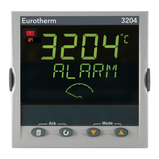
Page 33: Front Panel Layout
Front panel layout Beacons:- Measured Temperature Alarm active (Red) Lit when output 1 is ON (normally heating) Lit when output 2 is ON (normally cooling Target Temperature Lit when output 3 is ON (Setpoint ) Lit when output 4 is ON (normally alarm) Alternative setpoint in use (SP2) Meter (3208 and 3204 Remote setpoint or communications active... -
Page 34: To Set The Target Temperature (Setpoint)
4.4.1 To Set The Target Temperature 4.4.3 Auto, Manual and Off Mode (setpoint) The controller can be put into Auto, Manual or Off mode – see next section. In the HOME display:- Press to raise the setpoint Auto mode is the normal operation where the output is adjusted automatically by the controller in response to changes in the measured temperature. -
Page 35: To Select Auto, Manual Or Off Mode
4.4.4 To Select Auto, Manual or OFF Mode If manual mode has been selected, the MAN beacon will light. The upper display shows the measured temperature and the lower display the Press and hold (Mode) demanded output power. together for more than 1 second. The transfer from Auto to manual mode is This must be done in the HOME display. -
Page 36: Operator Parameters In Level 1
4.4.5 Operator Parameters in Level 1 The value of the parameter is shown in the upper Operator level 1 is designed for day to day operation display. Press to adjust this value. If no of the controller and access to these parameters is not key is pressed for 30 seconds the controller returns to protected by a pass code. -
Page 37: Operator Level 2
To Return to Level 1 5. Operator Level 2 Level 2 provides access to additional parameters. It is 1. Press and hold protected by a security code. to select LEv 1 2. Press To Enter Level 2 The controller will return to the level 1 HOME From any display press and hold display. - Page 38 By default the remote setpoint is scaled between SP.HI and SP.LO. Two further parameters (REM.HI and REM.LO) are available in a deeper level of access to limit the Remote SP range if required. See Engineering Handbook HA027986 which can be downloaded from www.eurotherm.co.uk. Part number HA028582. Issue 6.0...
- Page 39 Mnemonic Scrolling Display and description Range SETPOINT 1 Setpoint 1 value Alterable SP.HI to SP.LO SETPOINT 2 Setpoint 2 value Alterable SP.HI to SP.LO SP.RAT SETPOINT RATE LIMIT Rate of change of setpoint value. Alterable: OFF to 3000 display units per minute The following section applies to the Timer only –...
- Page 40 Mnemonic Scrolling Display and description Range END.T TIMER END TYPE This determines the behaviour of the timer when it Control OP goes has timed out. This value can be changed while the timer is running. to zero Control continues Dwel at SP1 Go to SP2 Reset...
- Page 41 Mnemonic Scrolling Display and description Range The following parameters are available when the timer is configured as a programmer – see also section 5.8 SERVO MODE. Sets the starting point for the ramp/dwell programmer SERVO Setpoint and the action on recovery from power failure. Temperature See also section 5.8.1 SP.rb...
- Page 42 Mnemonic Scrolling Display and description Range The following parameter is present if a motorised valve controller has been ordered MTR.T MOTOR TRAVEL TIME. Set this value to the time that it takes for the 0.0 to 999.9 seconds motor to travel from its fully closed to its fully open position. Note: In motorised valve control only the PB and TI parameters are active –...
- Page 43 Mnemonic Scrolling Display and description Range MANUAL RESET applies to a PD only controller i.e. the integral term is -100 to 100% turned off. Set this to a value of power output (from +100% heat, to - Default 0 100% cool which removes any steady state error between SP and PV. RELATIVE COOL GAIN adjusts the cooling proportional band relative to to 10.0 the heating proportional band.
- Page 44 Mnemonic Scrolling Display and description Range 1. (2, 3 or OUTPUT 1 (2, 3 or 4) MINIMUM PULSE TIME Sets the minimum on Relay outputs 0.1 to 150.0 4) PLS. and off time for the control output. seconds – default 5.0. Logic outputs Auto to 150.0 Ensure this parameter is set to a value that is suitable for -Default Auto = 55ms...
- Page 45 Mnemonic Scrolling Display and description Range HOME HOME DISPLAY Defines the parameter which appears in the lower Standard section of the HOME display Output power Time remaining ELAP Time elapsed First alarm setpoint Load current Clear (blank) Combined SP and time display CUSTOMER ID Sets a number from 0 to 9999 used as a custom 0 to 9999...
-
Page 46: Timer Operation
Timer Operation An internal timer can be configured to operate in one of four different modes. The mode is configured in Level 2 by the ‘TM.CFG’ (timer configuration) parameter. Each Timing Mode is described in the pages that follow. Operation Action Indication To Run the timer... -
Page 47: Dwell Timer
Dwell Timer If setpoint ramping is enabled, then the ramp completes before the timer starts. A dwell timer (‘ TI.CFG’ = ‘ DwEl ’ ) is used to control a process at a fixed temperature for a defined In the END state the behaviour is determined by the period. -
Page 48: Delayed Timer
Delayed Timer cooling off, until the time has elapsed. After the time has elapsed, the instrument controls at the ‘TI.CFG’ = ‘DELY’. The timer is used to switch target setpoint. on the output power after a set time. The timer starts immediately on power-up, or when run. -
Page 49: Soft Start Timer
Soft Start Timer after the dwell period (‘ DwEll’) . It is typically use to dry-out heaters in Hot Runner control systems ‘ TI.CFG’ = ‘SS.St’. A Soft Start timer starts automatically on power up. It applies a power limit (‘... -
Page 50: Programmer
Programmer followed by a dwell at that setpoint. These values are set by the user. The program profile is shown in the ‘ TI.CFG’ = ‘ProG ’. Function code CP contains a diagram four segment programmer where each segment consists of a controlled ramp rate to a target setpoint below. -
Page 51: Programmer Servo Mode And Power Cycling
5.8.1 Programmer Servo Mode and Power Cycling The way in which the program starts when ‘Run’ is selected or after the power is turned off and on again, is determined by the SERVO MODE parameter, as follows:- The program will start from the current setpoint value. On recovery from power failure, the program will reset. -
Page 52: To Operate The Programmer
5.8.2 To Operate the Programmer Operation of the programmer is the same as the timer. Operation Action Indication To Run a program Press and quickly Beacon -- RUN = On release Scrolling display - TIMER RUNNING To Hold a program Press and quickly Beacon -- RUN = Flashing release... -
Page 53: To Configure The Programmer
5.8.3 To Configure the Programmer Select Access Level 2 – see section 5.1. Operation Action Indication Notes Configure the Press to select ‘TM.CFG’ Timer as a Programmer Press to ‘ProG’ Set the In this example Dwell is set Press to select ‘TM.RES’... - Page 54 Set the Servo In this example the program Press to select ‘SERVO’ Mode will start from the current value of the process variable. Press to ‘PV’, ‘SP‘, See also section 5.8.1 ‘SP.rb’, or ‘PV.rb’ Set the first In this example the setpoint ...
- Page 55 This allows the programmer to repeat the set program up to 100 times. • An explanation of how to set up these parameters is given in the Engineering Handbook part number HA028651 which may be downloaded from www.eurotherm.co.uk. Part number HA028582. Issue 6.0...
- Page 56 Restriction of Hazardous Substances (RoHS) Product group 3200 Table listing restricted substances Chinese 限制使用材料一览表 产品 有毒有害物质或元素 铅 汞 镉 六价铬 多溴联苯 多溴二苯醚 3200 印刷线路板组件 附属物 显示器 表示该有毒有害物质在该部件所有均质材料中的含量均在SJ/T11363-2006 标准规定的限量要求以下。 表示该有毒有害物质至少在该部件的某一均质材料中的含量超出 SJ/T11363-2006 标准规定的限量要求。 English Restricted Materials Table Product Toxic and hazardous substances and elements...
- Page 57 Manuel Utilisateur...
- Page 59 Régulateurs de température PID Série 3200 Modèles No 3216, 3208, 32h8 et 3204 Table des matières Présentation générale de l'instrument ................. 4 Déballer le régulateur........................4 Dimensions .............................5 Etape 1 : Installation ........................7 1.3.1 Montage du régulateur sur le panneau..........................7 1.3.2 Dimensions des découpes de panneau ..........................7...
- Page 60 Réglage de la consigne souhaitée (consigne SP) ......................33 4.4.2 Indication d'alarme..................................33 4.4.3 Mode Auto/Manuel/Off ................................33 4.4.4 Sélection du Mode Auto, Manuel ou OFF ..........................34 4.4.5 Paramètres opérateur de niveau 1 ............................35 3200 Guide utilisateur HA028582FRA Indice 6.0 - mai 07...
- Page 61 Ce manuel - indice 6 - s’applique à la version logiciel 2.11 et plus pour les régulateur PID et à la version 2.21 et plus, pour les régulateurs VP Issue 6 de ce manuel inclut paramètres additionnels. 3200 Guide utilisateur HA028582FRA Indice 6.0 - mai 07...
-
Page 62: Présentation Générale De L'instrument
Si le code rapide indique température Série 3200. *****/****, le régulateur devra être configuré avant La Série 3200 est la garantie d'une régulation précise sa mise sous tension initiale. de la température des procédés industriels et se décline Le présent Guide d'utilisation vous explique étape par... -
Page 63: Dimensions
Modèle 3216 Vue de côté – Modèle 3216 Vue de dessus - Modèle 3216 1.25mm 48mm 90mm 48mm Pattes d'encrage Clip de retenue de panneau Joint d'étanchéité IP65 Clips de montage 3200 Guide utilisateur HA028582FRA Indice 6.0 - mai 07... - Page 64 2 Clip de retenue de panneau Joint d'étanchéité IP65 1.25mm 1.25mm 32h8 et 3204 vue de dessus 3208 vue de dessus sans Clip de retenue de panneau avec Clip de retenue de panneau 3200 Guide utilisateur HA028582FRA Indice 6.0 - mai 07...
-
Page 65: Etape 1 : Installation
être installés sur le même panneau, veiller à les espacer de la manière indiquée. Découpe pour 1/4 Découpe pour Monter le joint d'étanchéité IP65 derrière la façade de DIN 1/8 de DIN avant du régulateur. 3200 Guide utilisateur HA028582FRA Indice 6.0 - mai 07... -
Page 66: Espacements Minimum Entre Régulateurs
10mm Au remontage dans le boîtier, s'assurer que les clips sont bien engagés, afin que le niveau de protection IP65 soit maintenu. 38mm (Echelle libre) 3200 Guide utilisateur HA028582FRA Indice 6.0 - mai 07... -
Page 67: Code De Commande
D = Analogique (Sortie analogique - D : Sortie mA, pour une sortie * Uniquement sur les 3216 Comm’s EIA422/485 4 fils 6XX* en Volts, voir les numéros spéciaux champ13.) 3200 Guide utilisateur HA028582FRA Indice 6.0 - mai 07... -
Page 68: Etape 2 : Cablage
CT à HF. Les entrée CT/LA ne sont pas disponibles Voir le paragraphe 2.13.3 Légende des symboles Sortie Relais Entée Contact Sortie logique (SSR) Sortie triac Entrée transformateur de Courant Sortie analogique en mA 3200 Guide utilisateur HA028582FRA Indice 6.0 - mai 07... -
Page 69: Bornier De Raccordement - Régulateurs 3208 Et 3204
Ou Alim. basse tension 24Vac/dc Entrée 10 V Pt100 Module diviseur Vérifier la compatibilité du régulateur de tension avec l'alimentation réseau Vérifier avec la codification du régulateur livré Ref : SUB21/IV10 3200 Guide utilisateur HA028582FRA Indice 6.0 - mai 07... -
Page 70: Bornier De Raccordement Régulateurs 32H8
Module Diviseur de Tension CT HF HE HD AC AB Part No SUB21/IV10 B(-) A(+) COM Relais AA Communication Pt100 (OP4) Numérique ou Entrée consigne externe Voir Entrée10V paragraphe 2.7 2.49Ω 3200 Guide utilisateur HA028582FRA Indice 6.0 - mai 07... -
Page 71: Diamètres De Fil
Réf. : SUB21/V1 est nécessaire (non Entrée thermocouple fourni) L’alarme rupture Positif capteur ne fonctionne 100KΩ Négatif 0-10V pas lorsque cet 806Ω • adaptateur est installé. Utiliser un câble de compensation approprié, de préférence blindé. 3200 Guide utilisateur HA028582FRA Indice 6.0 - mai 07... -
Page 72: Entrée/Sortie 1 & Sortie 2
Sortie Etat non actif (OFF) : <300 mV, • Calibre : 0,75 Aeff, de 30 à 264 Vac <100μA 1(2)A résistif • Fonction de la sortie : chauffage, froid, alarme ou 1(2)B commande servomoteur d’ouverture ou de fermeture 3200 Guide utilisateur HA028582FRA Indice 6.0 - mai 07... -
Page 73: Entrée Consigne Externe
(>3,5mA ; < 22mA) elle sera utilisée comme la consigne principale. Si elle n’est pas valide ou non connectée, le régulateur tentera d’utiliser l’entrée Volts. La rupture capteur en mode Volts 3200 Guide utilisateur HA028582FRA Indice 6.0 - mai 07... -
Page 74: Sortie 4 (Relais Aa)
Logiciel configurable: 0-20 mA ou 4-20 • Résistance de charge maxi. : 500 Ω • Précision de la calibration : + < 0,25%, + < 50 μA • Fonction : chauffage, froid ou retransmission 3200 Guide utilisateur HA028582FRA Indice 6.0 - mai 07... - Page 75 également de prolonger la durée de vie des contacts du relais. Un circuit RC devrait aussi être connecté entre les bornes de la sortie Triac pour prévenir d’un déclenchement intempestif en cas de conditions de transitoires. 3200 Guide utilisateur HA028582FRA Indice 6.0 - mai 07...
-
Page 76: Entrées Logiques A Et B
Contact ouvert > 500 Ω. Contact fermé < 200 Ω • Fonctions de l'entrée : se reporter à la liste dans les codes rapides. ☺ Si la communication numérique EIA422 4fils est installée (3216 uniquement), l’entrée logique A n’est disponible. 3200 Guide utilisateur HA028582FRA Indice 6.0 - mai 07... -
Page 77: Transformateur De Courant
10A, 1 A de 11 à 100 A entrées ne sont donc pas isolées l'une de • l'autre ou par rapport à l'entrée PV. Précision de l'entrée CT : +4%. 3200 Guide utilisateur HA028582FRA Indice 6.0 - mai 07... -
Page 78: Communications Numériques (Option)
Tx Rx Com les autres régulateurs Terre RxA/ RxB/ Blindage HD Commun HD Co mmun HE Rx/Tx A(+) HE Rx A(+) HF Rx/Tx B(-) Terminaison 220 Ω HF Tx B(-) Paires torsadées 3200 Guide utilisateur HA028582FRA Indice 6.0 - mai 07... -
Page 79: Connexions Eia422 (3216 Uniquement)
Agir comme mémoire tampon du réseau EIA422/485 lorsque plus de 32 appareils sont nécessaires sur le bus de communication. • Faire le pont entre la EIA485 2fils et la EIA422 4 fils. 3200 Guide utilisateur HA028582FRA Indice 6.0 - mai 07... -
Page 80: Alimentation Électrique Du Régulateur
Pour 24 V ac/dc, fusible : T, 2 A 250 V sectionnement de l'équipement. Pour 100-240 Vac, fusible: T, 2 A 250 V Note : il est possible d'utiliser un seul interrupteur/ disjoncteur pour plusieurs instruments. 3200 Guide utilisateur HA028582FRA Indice 6.0 - mai 07... -
Page 81: Sécurité Et Compatibilité Électromagnétique (Cem)
EMC 89/336/EEC, par C et +75 application d'un fichier de procédure de construction technique. Cet instrument satisfait aux exigences générales en matière d'environnement industriel définies par la norme EN 61326. 3200 Guide utilisateur HA028582FRA Indice 6.0 - mai 07... -
Page 82: 3.1 Consignes De Sécurité À L'installation
électrostatiques provenant Personnel des personnes manipulant le régulateur. Pour prévenir ce Le personnel procédant à l'installation doit être risque, se décharger soi-même en touchant régulièrement titulaire de la qualification requise. 3200 Guide utilisateur HA028582FRA Indice 6.0 - mai 07... - Page 83 240 Vac. par la masse, ce qui met en conducteur cuivre pour tous les raccordements (sauf danger l'instrument. thermocouple) et se conformer à toutes les réglementations locales applicables au câblage 3200 Guide utilisateur HA028582FRA Indice 6.0 - mai 07...
- Page 84 Le capteur de température s'est détaché ; conductivité temporaire due à la condensation pourra • Il y a un court-circuit dans le câblage du cependant se produire dans certaines circonstances. thermocouple 3200 Guide utilisateur HA028582FRA Indice 6.0 - mai 07...
- Page 85 FN321 et FN612. protection complète dans toutes les conditions de défaut. Il Acheminement des câbles est à noter qu' Eurotherm commercialise à cet effet des Pour réduire les bruits électriques, les connexions dc unités d'alarmes indépendantes. basse tension et le câblage d'entrée du capteur devront Précautions d'installation en matière de CEM...
-
Page 86: Mise Sous Tension
Appuyer sur jusqu'à afficher Le code rapide se compose de 2 jeux Le régulateur passera automatiquement au niveau (“SET”) de 5 caractères. Le jeu opérateur. sélectionné est indiqué dans la moitié 3200 Guide utilisateur HA028582FRA Indice 6.0 - mai 07... - Page 87 Equivalent à la touche Descente 32-1472 Verrouillage clavier Réinitialisation/Marche pour Temporisation/Programme 32-1832 Sélection de consigne 2 Pause Temporisation/Programme 32-2912 32-2192 Réinitialisation pour Tempo/Prog Sélection Mode Standby 32-3272 32-2552 Validation de la consigne externe 3200 Guide utilisateur HA028582FRA Indice 6.0 - mai 07...
- Page 88 Sélection Mode Standby (Sorties Off) Sorties DC Retransmission Régulation 4-20, consigne 4-20 mA, chauffage 4-20, mesure 4-20 mA, refroidissement 4-20 mA, sortie 0-20 mA, chauffage 0-20, consigne 0-20 mA, refroidissement 0-20, mesure 0-20mA, sortie 3200 Guide utilisateur HA028582FRA Indice 6.0 - mai 07...
-
Page 89: Pour Rappeler Le Mode De Configuration Rapide
4 Cette procédure est décrite dans le manuel technique est active. 3200, No réf. HA028651 qui peut être téléchargé depuis le site www.eurotherm.co.uk. Note : si les codes rapides n'apparaissent pas au démarrage, il est probable que le régulateur a été... -
Page 90: Disposition De La Face Avant
Maintenir ce bouton enfoncé pour faire défiler les paramètres. charge four ni par le CT - Ecart de r égulation Appuyer pour modifier ou réduire une valeur. Appuyer pour modifier ou augmenter une valeur. 3200 Guide utilisateur HA028582FRA Indice 6.0 - mai 07... -
Page 91: Réglage De La Consigne Souhaitée (Consigne Sp)
Les alarmes sont configurées par défaut en tant de refroidissement sont désactivées (OFF). Les qu'alarmes non-mémorisées et désexcitées. Pour des alarmes et leurs sorties restent cependant actives. alarmes mémorisées, se reporter au manuel technique. 3200 Guide utilisateur HA028582FRA Indice 6.0 - mai 07... -
Page 92: Sélection Du Mode Auto, Manuel Ou Off
Pour revenir sur le mode Auto, appuyer sur en même temps. Appuyer ensuite sur Le régulateur reviendra sur l'écran HOME au bout de 2 secondes. pour sélectionner “Auto”. 3200 Guide utilisateur HA028582FRA Indice 6.0 - mai 07... - Page 93 Alarme de Bande rrc = Vitesse de variation (sens positif) Frc = Vitesse de variation (sens négatif) LD.AMP COURANT dans la CHARGE - Intensité Lecture seulement. Uniquement affiché si CT est configuré. 3200 Guide utilisateur HA028582FRA Indice 6.0 - mai 07...
- Page 94 (Par défaut, le code est ‘2’) En cas de saisie d'un code erroné, Pour faire défiler la liste dans le sens inverse, appuyer l'affichage reviendra sur le niveau 1. tout en maintenant le bouton enfoncé. 3200 Guide utilisateur HA028582FRA Indice 6.0 - mai 07...
- Page 95 Autorise la Marche, la Pause ou la Réinitialisation de la Réinitialisation temporisation. Marche hoLd Pause Fin de Tempo UNITS UNITES D'AFFICHAGE Unité des températures. Les pourcentages sont prévus pour des entrées linéaires. Kelvin nonE C (voyant éteint) PErc Pourcentage 3200 Guide utilisateur HA028582FRA Indice 6.0 - mai 07...
- Page 96 Note : l'option Programme n'est affichée que si elle a été commandée. Programme Prog TM.RES RESOLUTION TEMPORISATION Permet d'utiliser la temporisation en Heures Hour heures ou en minutes (disponible à la réinitialisation seulement). Minutes 3200 Guide utilisateur HA028582FRA Indice 6.0 - mai 07...
- Page 97 (SS.SP) ou que le temps défini (DWELL) se soit écoulé. La temporisation démarre automatiquement à la mise sous tension. 3200 Guide utilisateur HA028582FRA Indice 6.0 - mai 07...
- Page 98 CONSIGNE CIBLE 1. Définit la valeur de la consigne cible 1 RMP.1 RAMPE 1. Définit le taux d'évolution de la rampe 1 OFF, de 00:01 à 3000 unités par minute ou heure, configuré dans TM.RES 3200 Guide utilisateur HA028582FRA Indice 6.0 - mai 07...
- Page 99 à sa position ouverte. Note: Dans l cas d’une commande servomoteur, les paramètres PB et TI uniquement sont activés – voir page suivante. Le paramètre TD n'a aucun effet sur la commande. 3200 Guide utilisateur HA028582FRA Indice 6.0 - mai 07...
- Page 100 OFF. Sert à paramétrer sur une valeur 0 par défaut de sortie de puissance (de +100% chaud à -100% froid) permettant d'éliminer toute erreur de statisme en régime permanent entre SP et PV. 3200 Guide utilisateur HA028582FRA Indice 6.0 - mai 07...
- Page 101 Off = pas de zone neutre. 100 = chauffage et refroidissement désactivés. Pour régulateurs de type On/Off seulement. OP.HI LIMITE HAUTE de SORTIE Limite la puissance de chauffage maximale +100% to OP.LO appliquée au procédé. 3200 Guide utilisateur HA028582FRA Indice 6.0 - mai 07...
- Page 102 SEUIL SURINTENSITE Définit un point de déclenchement d'alarme Plage CT haute pour indiquer toute surintensité mesurée par le CT ADDR ADRESSE Adresse de communication du régulateur (de 1 à 254). 1 à 254 3200 Guide utilisateur HA028582FRA Indice 6.0 - mai 07...
- Page 103 ☺ Appuyer sur à n'importe quel moment pour revenir sur l'écran HOME en haut de la liste ☺ Appuyer continuellement sur pour faire défiler la liste ci-dessus. 3200 Guide utilisateur HA028582FRA Indice 6.0 - mai 07...
-
Page 104: Utilisation Avec La Temporisation
La temporisation peut également être MISE EN MARCHE, REGLEE SUR PAUSE ou REINITIALISEE via le paramètre ‘T.STAT’ (Etat de la temporisation). Elle peut également être commandée par le biais d'entrées numériques. 3200 Guide utilisateur HA028582FRA Indice 6.0 - mai 07... -
Page 105: Temporisation De Palier
Fin E N D . T = Temp. dwel THRES = + n Seuil Décompte Délai TEMPO Message déroulant TEMPORISATION RAZ - OFF REINIT. Entrée num. MARCHE 3200 Guide utilisateur HA028582FRA Indice 6.0 - mai 07... -
Page 106: Temporisation : Départ Différé
à la mise sous tension ou à la mise en cible. marche. Le régulateur reste en mode d'attente et Température SP1 (70) Délai Message TEMPO ON TEMPO OFF déroulant Marche Réinitialisation REINIT. Entrée num. MARCHE 3200 Guide utilisateur HA028582FRA Indice 6.0 - mai 07... -
Page 107: Temporisation De Démarrage Progressif
Temp. Consigne Consigne départ prog. SS. S P Temps Limite de puissance de départ progressif SS.PWR Temps Message déroulant TEMPO ON TEMPO OFF REINIT. Entrée num. MARCHE Réinitialisation Marche 3200 Guide utilisateur HA028582FRA Indice 6.0 - mai 07... -
Page 108: Programmateur
PALIER (paramètre par comme au segment précédent. défaut), ou d’effectuer une réinitialisation (RESET) Une sortie d'événement de simple est également disponible. Se reporter au manuel technique 3200 Guide utilisateur HA028582FRA Indice 6.0 - mai 07... -
Page 109: Mode Servo Et Cycle De Puissance Du Programmateur
(SP1 ou SP2) PV.rb Le programme démarrera à partir de la valeur mesurée. En cas de coupure de courant, le programme démarrera automatiquement avec la rampe préalablement définie pour la mesure. 3200 Guide utilisateur HA028582FRA Indice 6.0 - mai 07... - Page 110 Hors Sous Hors Sous rampe tension tension tension tension préalab lement définie SP et PV reprennent la rampe préalablement définie et la période de palier complète est répétée RMP.1 RMP.2 RMP.2 3200 Guide utilisateur HA028582FRA Indice 6.0 - mai 07...
-
Page 111: Fonctionnement Du Programmateur
Répéter la procédure ci-dessous pour exécuter à nouveau le programme (Note : il n'est pas essentiel de le réinitialiser une fois l'état Fin atteint). Les programmes peuvent également être activés à partir du paramètre « T.STAT » situé dans la liste des paramètres de niveau 2. 3200 Guide utilisateur HA028582FRA Indice 6.0 - mai 07... -
Page 112: Configuration Du Programmateur
Appuyer sur jusqu'à ‘Off’ ou consigne. ‘SP2‘ ou ‘Dwel’ programmateur OFF réglera la puissance de sortie sur Off et SP2 effectuera la régulation au point de consigne 2. 3200 Guide utilisateur HA028582FRA Indice 6.0 - mai 07... - Page 113 Appuyer sur pour sélectionner premier taux 100 sera visée progressivement à ‘RMP.1’ de rampe raison de 8,0 unités par heure. Appuyer sur pour ajuster Répéter ces trois étapes pour tous les segments 3200 Guide utilisateur HA028582FRA Indice 6.0 - mai 07...
- Page 114 100 fois. • Une description de la configuration de ces paramètres est disponible sur le manuel de configuration HA028651, qui peut être téléchargé sur le www.eurotherm.co.uk. 3200 Guide utilisateur HA028582FRA Indice 6.0 - mai 07...
- Page 115 Indicates that this toxic or hazardous substance contained in at least one of the homogeneous materials used for this part is above the limit requirement in SJ/T11363-2006. Approval Name: Position: Signature: Date: Martin Greenhalgh Quality Manager IA029470U600 (CN23172) Issue 1 Feb 07 3200 Guide utilisateur HA028582FRA Indice 6.0 - mai 07...
- Page 116 3200 Guide utilisateur HA028582FRA Indice 6.0 - mai 07...
- Page 117 Bedienungsanleitung...
- Page 119 Reglerwechsel ....................................8 Bestellcodierung ..........................9 Schritt 2: Verdrahtung ....................10 Klemmenbelegung Regler 3216 ......................10 Klemmenbelegung Regler 3208 und 3204...................11 Klemmenbelegung Regler 32h8......................12 Kabelquerschnitt..........................13 Fühlereingang (Messeingang) ......................13 Eingang/Ausgang 1 & Ausgang 2 ......................14 Externer Sollwerteingang ........................15 3200 Bedienungsanleitung, HA028582GER, Ausgabe 6.0, Mai-07...
- Page 120 Alarmanzeige ....................................32 4.4.2 4.4.3 Auto, Hand und Aus Modus..............................32 4.4.4 Auswahl von Auto, Hand oder Aus ............................33 4.4.5 Bedienparameter in Ebene 1..............................34 Bedienebene 2 ......................35 Zugriff auf Ebene 2 ..........................35 3200 Bedienungsanleitung, HA028582GER, Ausgabe 6.0, Mai-07...
- Page 121 Programmgeber Zyklen • EIA422 4-Leiter digitale Kommunikation, Option 6XX, nur für 3216 Ausgabe 6 dieser Bedienungsanleitung ist für PID Regler ab Softwareversion 2.11 und für Dripunkt-Schrittregler ab Softwareversion 2.21 gültig. Ausgabe 6 enthält zusätzliche Parameter. 3200 Bedienungsanleitung, HA028582GER, Ausgabe 6.0, Mai-07...
-
Page 122: Gerät
Installation und Grundlagen der Bedienung 1. Gerät Die Serie 3200 bietet Ihnen präzise Temperatur- Diese Bedienungsanleitung gibt Ihnen eine regelung für industrielle Prozesse und steht Ihnen in schrittweise Einführung für die Installation, drei Standard DIN Größen zur Verfügung: Verdrahtung, Konfiguration und Bedienung Ihres •... -
Page 123: Abmessungen
Abmessungen Unten sehen Sie eine Übersicht aller Regler mit den dazugehörigen Abmessungen. 3216 Oben 3216 Front 3216 Seitenansicht 1,250 mm 90 mm 48 mm Außen- klammern 48 mm IP65 Dichtung Rückhalteklammern Rückhalteklammern 3200 Bedienungsanleitung, HA028582GER, Ausgabe 6.0, Mai-07... - Page 124 96 mm 48 mm 96 mm 32h8 Seitenansicht mit Rückhalteklammern 90 mm 90 mm 1 Außenklammern 2 Rückhalteklammern 3 IP65 Dichtung 1,25 mm 1,25 mm 3208 Oben 32h8 und 3204 Oben ohne mit Rückhalteklammern Rückhalteklammern 3200 Bedienungsanleitung, HA028582GER, Ausgabe 6.0, Mai-07...
-
Page 125: Schritt 1: Installation
Frontrahmen des Reglers. 3. Stecken Sie den Regler in den Tafelausschnitt. 1/8 DIN Ausschnitt 1/4 DIN Ausschnitt 4. Bringen Sie die Halteklammern an ihren Platz. Zum Sichern des Reglers halten Sie das Gerät in 3200 Bedienungsanleitung, HA028582GER, Ausgabe 6.0, Mai-07... -
Page 126: Minimalabstände Zwischen Reglern
Reglers können Sie das Gerät aus dem Gehäuse entnehmen. 10 mm Wenn Sie das Gerät zurück in das Gehäuse stecken, versichern Sie sich, dass die Außenklammern einrasten. 38 mm (Nicht maßstabsgerecht) 3200 Bedienungsanleitung, HA028582GER, Ausgabe 6.0, Mai-07... -
Page 127: Bestellcodierung
500Ω ; 0-10Vdc OP CT & Digitaleingang A Triac ist mit Kleinspannungsoption nicht verfügbar. Externer SP und Logikeingang L = Logik; R = Relais; D = DC; T = Triac 4-Leiter RS485 Comms (nur 3216) 3200 Bedienungsanleitung, HA028582GER, Ausgabe 6.0, Mai-07... -
Page 128: Schritt 2: Verdrahtung
(1) Option 6XX - EIA422 dig. Kommunikation an Oder Best. Nr Klemmen CT bis HF. Externer Sollwerteingang SUB21/IV10 CT/LA Eingänge nicht verfügbar (Abschnitt 2.13.3. Symbolerklärung Logikausgang (SSR gesteuert) Relaisausgang Kontakteingang mA Analogausgang Triacausgang Stromwandlereingang 3200 Bedienungsanleitung, HA028582GER, Ausgabe 6.0, Mai-07... -
Page 129: Klemmenbelegung Regler 3208 Und 3204
100 bis 240 V AC 50/60 Hz 2,49Ω eingang Kleinspannung ODER 24 V AC/DC Pt100 Achten Sie auch die richtige Potentialteiler Modul 10V Eingang Spannungsversorgung für Ihren Regler. Best. Nr SUB21/IV10 Überprüfen Sie die Bestellcodierung des gelieferten Geräts. 3200 Bedienungsanleitung, HA028582GER, Ausgabe 6.0, Mai-07... -
Page 130: Klemmenbelegung Regler 32H8
3D 3C 24 V AC/DC 32h8 Regler Fühlereingang Potentialteiler Modul HE HD AC AB Best. Nr SUB21/IV10 B(-) A(+) COM AA Relais Digital Comms (OP4) Pt100 Oder Externer Sollwerteingang Eingang 2,49Ω mA/mV (Abschnitt 2.7) 3200 Bedienungsanleitung, HA028582GER, Ausgabe 6.0, Mai-07... -
Page 131: Kabelquerschnitt
Lieferumfang enthalten). Best. Nr: SUB21/IV10. Thermoelementeingang Bei Verwendung dieses Adapters kann die Funktion 0-10V Eingang • Verwenden Sie die passende Positiv des Fühlerbruch Alarms Ausgleichsleitung. Diese sollte Negativ nicht verwendet werden. möglichst geschirmt sein. 3200 Bedienungsanleitung, HA028582GER, Ausgabe 6.0, Mai-07... -
Page 132: Eingang/Ausgang 1 & Ausgang 2
Kontakt öffnen > 500 Ω. Kontakt Stellen Sie die Schaltrate des Ausgangs ein, um schließen < 150 Ω Beschädigungen am Ausgangsbauteil zu • vermeiden. (1.PLS oder 2.PLS in Abschnitt 5.3.). Eingangsfunktionen: Siehe Liste im Quick Start Code. 3200 Bedienungsanleitung, HA028582GER, Ausgabe 6.0, Mai-07... -
Page 133: Externer Sollwerteingang
• Die Kalibrierung des externen Sollwerts ist im Anzeige + <50 μA). Konfigurations Handbuch beschrieben. • Ausgangsfunktionen: Heizen, Kühlen oder • Ein lokaler SP Trimmwert ist in einer tieferen Retransmission. Ebene verfügbar (Konfig Handbuch). 3200 Bedienungsanleitung, HA028582GER, Ausgabe 6.0, Mai-07... -
Page 134: Ausgang 4 (Aa Relais)
Last fließen über den RC-Kreis 0,6 mA bei 110 V AC und 1,2 mA bei 240 V AC. Achten Sie darauf, dass dieser Strom keine elektrischen Lasten anzieht. Arbeiten Sie mit solchen Lasten, sollten Sie das RC-Glied nicht installieren. 3200 Bedienungsanleitung, HA028582GER, Ausgabe 6.0, Mai-07... -
Page 135: Digitaleingänge A & B
Schalten: 12 V DC bei 40 mA max • Kontakt offen > 500 Ω. Kontakt geschlossen < 200 Ω • Eingangsfunktionen: Siehe Liste des Quick Start Codes ☺ Haben Sie die EIA422 digitale Kommunikation, ist der Digitaleingang A nicht verfügbar. 3200 Bedienungsanleitung, HA028582GER, Ausgabe 6.0, Mai-07... -
Page 136: Stromwandler
3 und 10 V bei 50 mA liegen. • CT Eingangsauflösung: 0,1 A für den Bereich bis 10 A, 1A für den Bereich 11 bis 100 A. • CT Eingangsgenauigkeit: +4 % der Anzeige. 3200 Bedienungsanleitung, HA028582GER, Ausgabe 6.0, Mai-07... -
Page 137: Digitale Kommunikation
Verkettung zu Tx Rx Com weiteren Reglern HD Common RxA/ RxB/ HE Rx A(+) HF Tx B(-) HD Common Schirm HE Rx A(+) HF Tx B(-) Lokale Erde 220 Ω Abschluss- Twisted pairs widerstand 3200 Bedienungsanleitung, HA028582GER, Ausgabe 6.0, Mai-07... -
Page 138: Eia422 Anschlüsse (Nur 3216)
Die Kommunikationsumsetzer KD485 werden benötigt: • Als Schnittstelle zwischen 4-Leiterung und 2-Leiter Verbindungen. • Zum Puffern eines EIA422/485 Netzwerks, wenn mehr als 32 Geräte an einem Bus benötigt werden. • Als Bridge von 2-Leiter EIA485 auf 4-Leiter EIA422. 3200 Bedienungsanleitung, HA028582GER, Ausgabe 6.0, Mai-07... -
Page 139: Regler Spannungsversorgung
Für 24 V AC/DC Sicherung Typ T, 4 A 250 V. Einheit. Für 100/240 V AC Sicherung Typ T, 1 A 250 V. Anmerkung: Sie können einen Schalter oder Trennkontakt für mehrere Geräte verwenden. 3200 Bedienungsanleitung, HA028582GER, Ausgabe 6.0, Mai-07... -
Page 140: Sicherheit Und Emv
Das Gerät entspricht den allgemeinen Sollte das Gerät einen Fehler aufweisen, kontaktieren Richtlinien für industrielle Umgebung, definiert in EN Sie bitte die nächste Eurotherm Niederlassung. 61326. Weitere Details in den technischen Unterlagen. 3200 Bedienungsanleitung, HA028582GER, Ausgabe 6.0, Mai-07... - Page 141 Bauen Sie das System zum Schutz vor Berührung in Reinigung ein Gehäuse ein. Verwenden Sie für die Reinigung der Geräteaufkleber kein Wasser oder auf Wasser basierende Reinigungsmittel sondern Isopropyl Alkohol. Die Oberfläche der Geräte können Sie mit einer milden Seifenlösung reinigen. 3200 Bedienungsanleitung, HA028582GER, Ausgabe 6.0, Mai-07...
- Page 142 Versorgung zu Spannungen über entsprechende Stromstärke dimensioniert sind. 264 V AC kommen. Das Gerät kann dadurch zerstört Weiterhin sind alle Anschlüsse nach den gültigen werden. VDE-Vorschriften bzw. den jeweiligen Landesvorschriften vorzunehmen. 3200 Bedienungsanleitung, HA028582GER, Ausgabe 6.0, Mai-07...
- Page 143 Anzeigen der Alarme. In manchen Anwendungen wird der Sensor bei laufendem System gewechselt. In diesem Fall sollten Sie als zusätzlichen Schutz vor Stromschlag den Schirm des Temperatursensors erden. Verbinden Sie den Schirm nicht mit dem Maschinengehäuse. 3200 Bedienungsanleitung, HA028582GER, Ausgabe 6.0, Mai-07...
- Page 144 Verwenden Sie den Regler in einem Tischgehäuse, sind unter Umständen die Anforderungen der Fachgrundnorm für den Wohn-, Geschäft- und Gewerbebereich gültig. Bauen Sie in diesem Fall einen passenden Filter in das Gehäuse ein. Wir empfehlen Schaffner FN321 und FN612. 3200 Bedienungsanleitung, HA028582GER, Ausgabe 6.0, Mai-07...
-
Page 145: Einschalten
Die Anzeige zeigt Beschädigungen des Prozesses und zu Personenschäden führen. Es liegt in der Verantwortung des Inbetriebnehmers, für eine korrekte Konfiguration zu Wählen Sie mit oder sorgen. Der Regler geht automatisch in die Bedienebene. 3200 Bedienungsanleitung, HA028582GER, Ausgabe 6.0, Mai-07... - Page 146 Rezept 2/1 Auswahl 32-752 Hand Auswahl Externe MEHR Taste 32-1112 Timer/Programm Start Externe WENIGER Taste 32-1472 Tastensperre Timer/Prog Start/Reset 32-1832 Sollwert 2 Auswahl Timer/Programm Hold 32-2912 32-2192 Timer/Programm Reset Standby Auswahl 32-3272 32-2552 Freigabe externer SP 3200 Bedienungsanleitung, HA028582GER, Ausgabe 6.0, Mai-07...
- Page 147 Retransmission Regelung 4-20 mA Sollwert 4-20 mA Heizen 4-20 mA gemessene Temp. 4-20 mA Kühlen 4-20 mA Ausgang 0-20 mA Heizen 0-20 mA Sollwert 0-20 mA Kühlen 0-20 mA gemessene Temp. 0-20 mA Ausgang 3200 Bedienungsanleitung, HA028582GER, Ausgabe 6.0, Mai-07...
-
Page 148: Erneutes Aufrufen Des Quick Code Modus
Die OP4 Anzeige (Sollwert) leuchtet, wenn Anmerkung: Parameter können Sie auch in einer Ausgang 4 aktiv tieferen Ebene einstellen. Dies finden Sie im 3200 ist. Konfigurations Handbuch, Bestellnummer HA028651GER. Anmerkung: Erscheint der Quick Code während der Startphase nicht, wurde der Regler in einer höheren Zugriffsebene neu konfiguriert und der... -
Page 149: Bedienoberfläche
Ansicht zurück in die Hauptanzeige. - Fehlersignal Diese Taste dient der Auswahl eines Parameters. Halten Sie die Taste gedrückt, laufen die Parameter durch. Taste zum Ändern/Erhöhen eines Werts. Taste zum Ändern/Verringern eines Werts. 3200 Bedienungsanleitung, HA028582GER, Ausgabe 6.0, Mai-07... -
Page 150: Einstellen Des Sollwerts
Bitte verwenden Sie einen im Alarmfall stromlos konfiguriert. Wie Sie die separaten ‘Übertemperatur’ Regler. Einstellung ändern, finden Sie im Konfigurations Beim Aus Modus sind Heiz- und Kühlausgänge aus. Handbuch beschrieben. Die Alarmausgänge sind weiterhin aktiv. 3200 Bedienungsanleitung, HA028582GER, Ausgabe 6.0, Mai-07... -
Page 151: Auswahl Von Auto, Hand Oder Aus
+ u der oberen Anzeige dargestellt. während Sie diese Tasten drücken. Nach 2 s geht der Regler Zurück zum Automatikbetrieb kommen Sie, wieder in die Hauptanzeige. indem Sie gleichzeitig drücken. Wählen Sie dann mit ‘Auto’. 3200 Bedienungsanleitung, HA028582GER, Ausgabe 6.0, Mai-07... -
Page 152: Bedienparameter In Ebene 1
= Abweichung Hoch; d.LO = Abweichung Tief; A3.xxx ALARM 3 SOLLWERT d.Bd = Abweichung Band A4.xxx ALARM 3 SOLLWERT rrc = Positiver Gradient; Frc = Negativer Gradient Eingestellt in technischen Einheiten/Minuten LD.AMP LASTSTROM Laststrom Schreibgeschützt und nur, wenn CT konfiguriert 3200 Bedienungsanleitung, HA028582GER, Ausgabe 6.0, Mai-07... -
Page 153: Bedienebene 2
In der Liste zurückgehen können Sie, indem Sie drücken, während Sie halten. 7. Geben Sie ein falsches Passwort ein, geht die Anzeige wieder auf Ebene 1. Der folgenden Liste können Sie die in Ebene 2 verfügbaren Parameter entnehmen. 3200 Bedienungsanleitung, HA028582GER, Ausgabe 6.0, Mai-07... - Page 154 Der externe Sollwert wird zwischen SP.HI und SP.LO skaliert. In einer tieferen Ebene sind zwei weitere Parameter verfügbar (REM.HI und REM.LO), um den externen SP Bereich zu begrenzen. Weitere Informationen im Konfigurations Handbuch, HA027986GER. 3200 Bedienungsanleitung, HA028582GER, Ausgabe 6.0, Mai-07...
- Page 155 Einheiten/Minute bestimmte Vortemperatur garantiert. Sie können den Schwellwert auf AUS setzen. In diesem Fall wird der Wert ignoriert und der Timer startet sofort. Haben Sie eine Sollwertrampe eingestellt, wird die Rampe vor Timerstart beendet. 3200 Bedienungsanleitung, HA028582GER, Ausgabe 6.0, Mai-07...
- Page 156 TIMER LAUFZEIT – kann bei laufendem Timer eingestellt werden. Der 0:00 bis 99.59 hh:mm: oder Parameter erscheint nur bei Haltezeit Timern. mm:ss T.REMN RESTLAUFZEIT Verbleibende Timerzeit. Diesen Wert können Sie bei 0:00 bis 99.59 hh:mm: oder laufendem Timer verändern. mm:ss 3200 Bedienungsanleitung, HA028582GER, Ausgabe 6.0, Mai-07...
- Page 157 Zeichen der Mnemonik beschreiben die Alarmart: A3.xxx HI = Maximalalarm, LO = Minimalalarm A4.xxx DHI = Abweichung Hoch, DLO = Abweichung Tief BND = Abweichungsbandalarm rrc = Positiver Gradient; Frc = Negativer Gradient Eingestellt in technischen Einheiten/Minuten 3200 Bedienungsanleitung, HA028582GER, Ausgabe 6.0, Mai-07...
- Page 158 Ausgang proportional zur Amplitude und Dauer des Fehlersignals anhebt Vorgabe: 360 oder absenkt. DIFFERENTIALZEIT ist proportional zur Änderungsrate des Prozesswerts. Off bis 9999 Sekunden Der Differentialanteil verhindert Über- und Unterschwinger am Sollwert. Vorgabe: 60 für PID Vorgabe: 0 für Schrittregelung 3200 Bedienungsanleitung, HA028582GER, Ausgabe 6.0, Mai-07...
- Page 159 Ausgang eingeschaltet ist. des Kühlen Aus = Kein Todband. 100 = Heizen und Kühlen Aus. Proportionalbands Nur für Ein/Aus Regler. OP.HI AUSGANG HOCH begrenzt die maximale Heizleistung oder die minimale +100% bis OP.LO Kühlleistung. 3200 Bedienungsanleitung, HA028582GER, Ausgabe 6.0, Mai-07...
- Page 160 CT Bereich den Leckstrom, gemessen vom CT. HC.ALM ÜBERSTROM ALARM SCHWELLE setzt den Maximalalarm Schaltpunkt CT Bereich für Überstrom. Gemessen vom CT. ADDR ADRESSE – Kommunikationsadresse des Reglers. 1 bis 254 1 bis 254 3200 Bedienungsanleitung, HA028582GER, Ausgabe 6.0, Mai-07...
- Page 161 Rezept. Bis zu 5 Rezepte sind möglich. nach dem Speichern ☺ kommen Sie immer wieder zurück zur Hauptanzeige am Anfang der Liste. ☺ Halten Sie die Taste gedrückt, laufen die Parameter der Liste schneller durch 3200 Bedienungsanleitung, HA028582GER, Ausgabe 6.0, Mai-07...
-
Page 162: Timer
Anmerkung: Es ist nicht nötig, den Timer nach Erreichen des Ende Status zurückzusetzen. Sie können den Timer auch über den Parameter ‘T.STAT’ (Timer Status) starten, stoppen oder zurücksetzen. Wenn konfiguriert, haben Sie auch die Möglichkeit, den Timer über Digitaleingänge zu regeln. 3200 Bedienungsanleitung, HA028582GER, Ausgabe 6.0, Mai-07... -
Page 163: Haltezeit Timer
Haben Sie für den Schwellwert AUS gewählt, startet laufendem Timer ändern. der Timer direkt. Ende Status e n d. t = Temp dwel THRES = + n Counting down Zeit TIMER ENDE Durchlaufende TIMER LAEUFT Meldung RESET Digitaleingang 3200 Bedienungsanleitung, HA028582GER, Ausgabe 6.0, Mai-07... -
Page 164: Verzögerungs Timer
Nachdem die Timerzeit abgelaufen ist, regelt das eingestellten Zeit einzuschalten. Der Timer startet Gerät am Zielsollwert. direkt nach dem Einschalten oder wenn Sie ihn Temperatur Sollwert Zeit Durchlaufende TIMER LAEUFT TIMER ENDE Meldung Reset RESET Digitaleingang 3200 Bedienungsanleitung, HA028582GER, Ausgabe 6.0, Mai-07... -
Page 165: Soft Start Timer
Regelsystemen verwenden. Timer schaltet dem Ausgang eine Leistungsbegrenzung (‘ SS.PWR’ ) auf, bis die Temp Sollwert Soft start Sollwert SS.SP Zeit Soft Start Leistungsgrenze SS.PWR Zeit Durchlaufende TIMER LAEUFT TIMER ENDE Meldung RESET Digitaleingang Reset 3200 Bedienungsanleitung, HA028582GER, Ausgabe 6.0, Mai-07... -
Page 166: Programmgeber
TIMER ENDE – Ist Ende Typ = SP2, wird TIMER ENDE erst aktiv, wenn die Rampe beendet oder SP2 erreicht ist. Eine DWELL (Haltezeit) oder Reset als Ende Typ wird eher verwendet (Voreinstellung). 4. Die Verwendung des Ereignisausgangs finden Sie im Konfigurations Handbuch erklärt. 3200 Bedienungsanleitung, HA028582GER, Ausgabe 6.0, Mai-07... -
Page 167: Programmgeber Servo Modus Und Netzausfall
Das Verhalten des Programmgebers nach einem Netzausfall sehen Sie unten für SERVO = SP.rb und PV.rb dargestellt: Netz Netz Netz Netz SP (und PV) steigen mit der zuletzt verwendeten Rampensteigung SP (und PV) steigen mit der zuletzt verwendeten Rampensteigung und wiederholen die gesamte Haltezeit. RMP.1 RMP.2 RMP.2 3200 Bedienungsanleitung, HA028582GER, Ausgabe 6.0, Mai-07... -
Page 168: Bedienung Des Programmgebers
Mit dem oben genannten Vorgehen können Sie das Programm erneut starten (Anmerkung: es ist nicht nötig, das Programm nach Erreichen des Ende Status zurückzusetzen.) Das Programm können Sie auch über den Parameter T.STAT in der Ebene 2 Parameterliste bedienen. 3200 Bedienungsanleitung, HA028582GER, Ausgabe 6.0, Mai-07... -
Page 169: Konfiguration Des Programmgebers
Gehen Sie mit auf ‘END.T’ einstellen Gerät weiter auf dem letzten Sollwert. Wählen Sie mit oder ‘Off’ oder ‘SP2‘ oder ‘Dwel’ OFF schaltet den Ausgang ab und bei SP2 regelt das Gerät am Sollwert 2. 3200 Bedienungsanleitung, HA028582GER, Ausgabe 6.0, Mai-07... - Page 170 Erste Rampen- Gehen Sie mit auf RMP.1. Rampe mit einer Steigung steigung von 8,0 Einheiten pro Stellen Sie mit oder einstellen. Stunde. Wert ein. Wiederholen Sie die oben genannten Schritte für alle Segmente. 3200 Bedienungsanleitung, HA028582GER, Ausgabe 6.0, Mai-07...
- Page 171 ‘Programmgeber Zyklen’ stehen Ihnen bei PID Reglers ab Softwareversion 2.09 und bei Schrittreglern ab Version 2.29 zur Verfügung. Damit können Sie ein Programm bis zu 100 mal wiederholen lassen. • Erklärungen über diese Parameter finden Sie im Konfigurations Handbuch, Bestellnummer HA028651GER. 3200 Bedienungsanleitung, HA028582GER, Ausgabe 6.0, Mai-07...
- Page 172 Indicates that this toxic or hazardous substance contained in at least one of the homogeneous materials used for this part is above the limit requirement in SJ/T11363-2006. Approval Name: Position: Signature: Date: Martin Greenhalgh Quality Manager IA029470U600 (CN23172) Issue 1 Feb 07 3200 Bedienungsanleitung, HA028582GER, Ausgabe 6.0, Mai-07...
- Page 174 The information in this document is given in good faith, but is intended for guidance only. Eurotherm Limited will accept no responsibility for any losses arising from errors in this document. Invensys, Eurotherm, the Eurotherm logo, Chessell, EurothermSuite, Mini8, EPower, Eycon, Eyris and Wonderwear are trade- marks of Invensys plc, its subsidiaries and affiliates.
Need help?
Do you have a question about the 3200 and is the answer not in the manual?
Questions and answers