Table of Contents
Advertisement
Quick Links
Advertisement
Table of Contents

Related Manuals for Eurotherm 2208e


Summary of Contents for Eurotherm 2208e
- Page 1 TEMPERATURE CONTROLLERS Installation and operation handbook...
-
Page 3: Table Of Contents
ALARMS..................1-22 1.11.1 Types of Alarm Used in the 2200...........1-22 1.12 ALARM RELAY OUTPUT ............1-23 1.12.1 SETTING ALARM LEVELS ............1-24 1.12.2 ALARM INDICATION AND ACKNOWLEDGEMENT .....1-25 1.12.3 DIAGNOSTIC ALARMS ..............1-26 2208e and 2204e Controller Handbook Part No. HA026696 Issue 3.0 Nov-03... - Page 4 SELECTING AN ACCESS LEVEL ..........3-3 3.3.2 Returning to Operator Level ..............3-5 EDIT LEVEL ..................3-5 3.4.2 Hiding or revealing a complete list ............3-6 3.4.3 Promoting a parameter................ 3-6 2208e and 2204e Controller Handbook Part No. HA026696 Issue 3.0 Nov-03...
- Page 5 Chapter 6 USER CALIBRATION............6-1 WHAT IS THE PURPOSE OF USER CALIBRATION? ....6-2 USER CALIBRATION ENABLE ............6-3 6.10 SINGLE POINT CALIBRATION ...........6-4 6.11 TWO POINT CALIBRATION............6-5 6.12 CALIBRATION POINTS AND CALIBRATION OFFSETS...6-6 2208e and 2204e Controller Handbook Part No. HA026696 Issue 3.0 Nov-03...
- Page 6 To Configure Low and High Current Trip Alarms......9-10 9.9 TO ATTACH SOFT ALARMS TO A RELAY OUTPUT ....9-11 9.10 THE SCALING FACTOR ............9-12 9.1.7 To adjust the scaling factor ............9-12 2208e and 2204e Controller Handbook Part No. HA026696 Issue 3.0 Nov-03...
- Page 7 This product is covered by one or more of the following US Patents: 5,484,206 and 5,793,754; Additional patents pending. PDSIO is a registered trademark of Eurotherm. INSTANT ACCURACY™, SSRx Load Doctor™ and SSRx Enhanced Load Doctor ™...
- Page 8 Contents Installation and Operation Handbook Symbols in Use In This Handbook Useful information Button Operation Caution, (refer to the Functional earth accompanying documents) (ground) terminal 2208e and 2204e Controller Handbook Part No. HA026696 Issue 3.0 Nov-03...
- Page 9 1.10.9 Communications List ...............21 1.10.10 Access List ..................21 1.11 alarms..................22 1.11.1 Types of Alarm Used in the 2200 ............22 1.12 Alarm relay output..............23 1.12.1 SETTING ALARM LEVELS .............24 1.12.2 ALARM INDICATION AND ACKNOWLEDGEMENT.......25 1.12.3 DIAGNOSTIC ALARMS..............26 2208e and 2204e Controller...
-
Page 10: Installation And Operation Handbook
Setpoint 2 active PDS Remote Setpoint Setpoint rate limit active Manual mode Page Scroll Down Button Button Button Button Figure 1-1 Model 2208e front panel layout 2204e Output 1 Output 2 20.00 Upper readout 20.00 Lower readout Setpoint 2 active Remote Setpoint... - Page 11 Press to decrease a value in the lower readout. Up button Press to increase a value in lower readout. Figure 1.3 Controller buttons and indicators For Valve Positioning, please refer to Appendix D ‘Motorised Valve Control 2208e and 2204e Controller...
-
Page 12: Getting Started
Operation Installation and Operation Handbook GETTING STARTED Thank you for selecting the 2208e/2204e controller. This section shows the principle of operation. 1.2.1 Viewing The Process Value and Setpoint Install and wire up the controller in accordance with Chapter 2 and switch on. Following a 3... -
Page 13: Viewing The Display Units
- - - A A A A Manual/Auto Auto Auto Auto Auto Actual state Keep pressing to return to the Home display or select further parameters (if available) Figure 1.6 Upper readout is parameter name. Lower is value 2208e and 2204e Controller... -
Page 14: Use Of The 'Page' Button
Figure 1.7 Press to choose a parameter list The actual list headings may be longer or shorter than indicated above and you can customise this for the operator’s convenience in EDIT level, Chapter 3. 2208e and 2204e Controller... -
Page 15: Parameter Lists
If, at any time, no key is pressed within 45 seconds, the display will always return to the “HOME” display. A complete description of the parameter lists is given on page 1-14. 2208e and 2204e Controller... -
Page 16: Manual Or Automatic Control
3rd press m m m m - - - - A A A A Manual/Auto to select Auto Auto automatic mode Auto Auto manual mode Keep pressing to return to “HOME” display Figure 1.9 Auto/Manual select 2208e and 2204e Controller... -
Page 17: How To Manually Adjust Output Power
To change the value (or state) of a parameter press the Raise button or the Lower button The remainder of this chapter provides a complete list of all parameters available. 2208e and 2204e Controller... -
Page 18: Selecting Setpoint 1 Or Setpoint 2
SSEL SSEL When setpoint 2 is Press SP 1 SP 1 SP 1 SP 1 selected the SP2 beacon change between SP 1 and illuminates. SP 2 Figure 1-11 To Select Setpoint 1 or 2 1-10 2208e and 2204e Controller... -
Page 19: Ramp Dwell Function
The program will go into rSEt rSEt rSEt rSEt standby Press to choose dwel The program will dwell for an the action required at the end of unlimited period the dwell time Figure 1-12 Ramp/Dwell Program 2208e and 2204e Controller 1-11... -
Page 20: To Run The Program
During Dwell. After return of power the working setpoint will servo to PV, the ramp continues to SP2 followed by full programmed dwell. In effect this causes the program to restart. Use the Hide, Reveal and Promote features to customise the display for a programmer. See Chapter 3. 1-12 2208e and 2204e Controller... -
Page 21: Location Of Parameters - Block Diagram
These are available in configuration level only Logic, triac /Invert output Logic Inputs Retrans-mission Functions LA, LB, 2 to 5 logic Retrans- listed in Module 2 inputs mission LA/LB conf Logic I/P Volts lists Figure 1-14 Controller Block Diagram 2208e and 2204e Controller 1-13... -
Page 22: Navigation Diagram (Part A)
The navigation diagram shows a full list of SP2.L possible parameters. However, some may not appear because they are dependent upon the particular controller variant. SP2.H End.t rset 100.0 Loc.L ProG 100.0 rset Loc.H StAt Figure 1.15a Navigation diagram SPrr 1-14 2208e and 2204e Controller... -
Page 23: Navigation Diagram (Part B)
Complete lists or individual parameters normally hidden in Operator level. To see all the available parameters you must select Full level. See Chapter 3, Access Levels Only displayed when option selected Figure 1.15b Navigation diagram 2208e and 2204e Controller 1-15... -
Page 24: Parameter Tables
Auto diSP Configure lower None readout of home AmPS display stat vPoS 9999 Customer ID Additional parameters may appear in the Home display if the ‘promote’ feature has been used (see Edit Level, Chapter 3). 1-16 2208e and 2204e Controller... -
Page 25: Alarm List
Hy.EV 9999 Hysteresis for event alarms. See display Note 1 9999 Loop break time secs Note 1: This parameter has been added from software version 4. Event alarms are configured in the AL Conf List 2208e and 2204e Controller 1-17... -
Page 26: Autotune List
Derivative time seconds 0.00 100.0 Manual reset (appears when ti set to OFF) Auto Auto 9999 Cutback low display Auto Auto 9999 Cutback high display rEL.C 1.00 1.00 0.01 9.99 Relative cool gain (set 1) 1-18 2208e and 2204e Controller... -
Page 27: Setpoint List
SPrr Setpoint rate limit Units per minute dwEl Dwell time 0.1 to 999.9 minutes EnD.t rset rset rset End type hoLd Stby dwel ProG rset rset Program control rset Stat Status of program dwel 2208e and 2204e Controller 1-19... -
Page 28: Input List
1.10.6 On/Off List OnOf OnOf OnOf OnOf On/off list This set of parameters only appear if On/Off control has been configured hYS.H 9999 Heat hysteresis display hYS.C 9999 Cool hysteresis display HC.db 9999 Heat/Cool dead band display 1-20 2208e and 2204e Controller... -
Page 29: Output List
1.10.9 Access List ACCS ACCS ACCS ACCS Access list codE 9999 Full and Edit level password Goto Goto level - OPEr OPEr OPEr conF OPEr FuLL Edit or conF ConF 9999 Configuration level password 2208e and 2204e Controller 1-21... -
Page 30: Alarms
Process Variable (PV) Deviation High Deviation Setpoint (SP) Band Deviation Low Full Scale Low Rate of Change Output State Full scale Deviation Deviation high Deviation band Full scale high Rate of change Time Figure 1-17: Alarm Types 1-22 2208e and 2204e Controller... -
Page 31: Alarm Relay Output
See Chapter 5 for further information. Alarm 1 Relay Alarm 2 output Alarm 3 SEnS Input fail Sensor break Any combination of alarms can operate the relay. Typical alarms are shown Figure 1-18: Attaching Alarms to an Output 2208e and 2204e Controller 1-23... -
Page 32: Setting Alarm Levels
4 4 4 4 -- - - - - to change 5th press Loop break time t t t t to change Press to return to list header Figure 1-19 To Set Alarm Trip Levels 1-24 2208e and 2204e Controller... -
Page 33: Alarm Indication And Acknowledgement
If a relay has been attached to the alarm output (see Chapter 7 ‘Alarm Operation’), it will operate when the alarm condition occurs and remain in the operated condition until the alarm is acknowledged AND it is no longer present 2208e and 2204e Controller 1-25... -
Page 34: Diagnostic Alarms
This error message normally occurs when pre- No I/O module configuring a controller without installing any of the Modules are configured but not fitted required I/O modules Figure 1.20a Diagnostic alarms - continued on the next page 1-26 2208e and 2204e Controller... - Page 35 Acknowledge by pressing ‘page’ button error alarm occurs and ‘scroll’ button together. Figure 1.20b Diagnostic alarms *If the user has disassembled and reassembled the instrument, this error can occur if any connectors are not seated properly. 2208e and 2204e Controller 1-27...
- Page 36 Operation Installation and Operation Handbook 1-28 2208e and 2204e Controller...
- Page 37 Installation and Operation Handbook Installation 2 Chapter 2 INSTALLATION 2 Chapter 2 INSTALLATION ..........1 INSTRUMENT LAYOUTS..............2 2.1.2 Outline Dimensions Model 2208e ............3 2.1.3 Outline Dimensions Model 2204e ............3 INTRODUCTION ................4 2.2.2 Controller labels ..................4 MECHANICAL INSTALLATION ............4 2.3.2 Unplugging and plugging-in the controller..........4 WIRING .....................5...
-
Page 38: Chapter 2 Installation
Installation Installation and Operation Handbook INSTRUMENT LAYOUTS Display screen Latching ears Panel sealing gasket Panel retaining clips Label Sleeve Connection Terminals Keypad Figure 2-1: 2208e 1/8 DIN controller Figure 2-2: 2204e 1/4 DIN controller 2208e and 2204e Controller... -
Page 39: Outline Dimensions Model 2208E
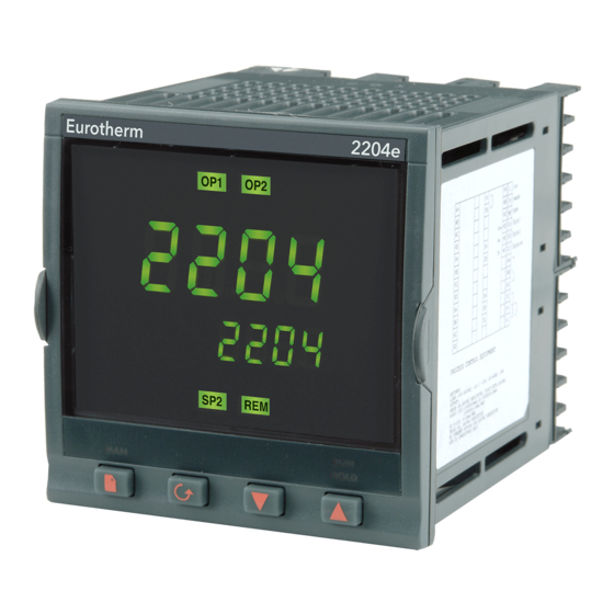
(3.78in) +0.03 +0.02 Recommended 10mm 38mm minimum spacing of (0.4in) (1.5in) controllers (Not to scale Figure 2-3: Outline dimensions Model 2208e controller 2.1.3 Outline Dimensions Model 2204e 103mm (4.01in) 96mm (3.78in) 2204 OP1 OP2 20.0.0 96mm 3.78in 20.0.0 20.0.0 20.0.0 20.0.0... -
Page 40: Introduction
Installation and Operation Handbook INTRODUCTION The Models 2208e and 2204e are precision temperature controllers with self tuning. They have a modular hardware construction which provides two control outputs, two alarm relays and one communications port. Two logic inputs are provided as standard. In addition the Model 2204e has an optional plug-in 10A relay heating output. -
Page 41: Wiring
Output 2 Common Output 3 Output 4 Pt100 Figure 2-5: Model 2208e wiring connections The ground connection is not required for electrical safety but must be connected to ensure EMC performance is optimised. *Do not use unused terminals as wire holders. -
Page 42: Wire Sizes
Output 4 Pt100 Figure 2-6: Model 2204e Wiring connections *The ground connection is not required for safety purposes but must be connected to ensure EMC performance is optimised. *Do not use unused terminals as wire holders. 2208e and 2204e Controller... -
Page 43: Sensor Input Connections
(18Vdc, 20mA max) in output 2 *Logic output can also be configured as logic input on module 2A. PDS Mode 1 & 2 are only supported in Module 1A. Figure 2-8: Outputs 1 and 2 connections 2208e and 2204e Controller... -
Page 44: Pds Modes
When a relay contact is used in an alarm circuit ensure that the current passing through the snubber when the relay contact is open does not hold in low power electrical loads and thereby interfere with the failsafe operation of the alarm circuit. 2208e and 2204e Controller... -
Page 45: Typical Single Loop Wiring Diagram
Cooling Power Fuse Fuse 1A(T) 2A(T) Output 1 logic heating Output 2 Snubber Triac cooling Heating power fuse (load dependent) Solid State Relay Cooling Heater Solenoid Valve Thermocouple Figure 2-9: Typical wiring diagram, Model 2208e Controller 2208e and 2204e Controller... -
Page 46: Rs 232/485/422 Communication Connections
2-wire EIA-485 serial Do not Do not Common A (+) B (-) communications EIA-232 serial Not used Not used Common communications PDS Setpoint input Not used Not used Not used Signal Common Figure 2-10: Communication connections 2-10 2208e and 2204e Controller... -
Page 47: Wiring Of Eia-485 Serial Communication Links
Series 2000™ Controller Note: All termination resistors are 220 ohm 1/4W carbon composition. Local grounds are at equipotential. Where equipotential is not available wire into separate zones using a galvanic isolator. Figure 2-11: 2-wire EIA-485 wiring 2208e and 2204e Controller 2-11... -
Page 48: Devicenet Wiring To Series 2200E Controllers
Installation and Operation Handbook 2.10 DEVICENET WIRING TO SERIES 2200E CONTROLLERS This section covers the DeviceNet digital communications option for the model 2208e and 2204e PID controllers. To configure DeviceNet communications refer to pages 5-16 and 5-17. 2.10.2 DeviceNet Terminal Functions... -
Page 49: Wiring Interconnections For Devicenet Communications
2200e Controller Network Supply 24Vdc ( +1%) 250mV p-p Ripple 121! (SLAVE) Address N+1 Daisy chain to further Fit to last instrument instruments in the chain Figure 2-12: 2-Wiring Connections for 2200e Series DeviceNet Controllers 2208e and 2204e Controller 2-13... - Page 50 Installation Installation and Operation Handbook 2-14 2208e and 2204e Controller...
-
Page 51: Chapter 3 Access Levels
3 Chapter 3 ACCESS LEVELS..........1 THE DIFFERENT ACCESS LEVELS ..........2 SELECTING AN ACCESS LEVEL ...........3 3.3.2 Returning to Operator Level..............5 Edit level...................5 3.4.2 Hiding or revealing a complete list ............6 3.4.3 Promoting a parameter .................6 2208e and 2204e Controller... -
Page 52: The Different Access Levels
You can also promote parameters to the home list. (See Edit level at the end of the chapter). ConF Configuration This special level allows access to set up the fundamental characteristics of the controller. Figure 3-1 Access levels 2208e and 2204e Controller... -
Page 53: Selecting An Access Level
(If an incorrect password has been entered and the controller is still ‘locked’ then pressing Scroll at this point will simply return you to the aCCs list header.) Note: From this code display, you can access “read only” configuration level by pressing together. To escape, press together 2208e and 2204e Controller... -
Page 54: Level Selection
Press the Scroll button 3.2.6 Configuration level The first display of configuration is shown. See chapter 5, inSt Configuration for details of the configuration parameters. For instructions on leaving configuration level see Chapter 5, Configuration. ConF 2208e and 2204e Controller... -
Page 55: Returning To Operator Level
HidE Hides a parameter or list header. HidE HidE HidE For example: 2FSL The parameter selected is the set point for Alarm 2 - Full Scale Low ALtr It will be alterable in Operator level 2208e and 2204e Controller... -
Page 56: Hiding Or Revealing A Complete List
Scroll through the lists to the required parameter and choose the ‘Pro’ code. The parameter is then automatically added (promoted) into the Home display list (the parameter will also be accessible as normal from the standard lists. a maximum of 12 parameters can be promoted. Promoted parameters are automatically ‘alterable’. 2208e and 2204e Controller... - Page 57 4.3. How to Tune ..................4 4.3.1. Typical automatic tuning cycle ..............5 4.3.2. Calculation of the cutback values............5 4.4. MANUAL TUNING ................6 4.4.1. Setting the cutback values ..............7 4.4.2. Integrating action and manual reset............8 4.4.3. Automatic droop compensation (Adc) ...........8 2208e and 2204e Controller...
-
Page 58: Chapter 4 Tuning
Relative cool Only present if cooling has been configured. Sets the cooling gain proportional band by dividing the Pb value by the rEL.C value. Table 4-1 Tuning parameters 2208e and 2204e Controller... -
Page 59: Automatic Tuning
This method automatically determines the value of the parameters listed in table 4-1 on the previous page. The 2208e and 2204e use a ‘one-shot’ tuner which works by switching the output on and off to induce an oscillation in the measured value. From the amplitude and period of the oscillation, it calculates the tuning parameter values. -
Page 60: How To Tune
If you want ‘Proportional only’ or ‘PD’ or ‘PI’ control, you should set the ‘ti’ or ‘td’ parameters to OFF before commencing the tuning cycle. The tuner will leave them off and will not calculate a value for them. For valve position tuning and set-up, please refer to Appendix D. 2208e and 2204e Controller... -
Page 61: Typical Automatic Tuning Cycle
(for example, under startup conditions). If either low cutback or high cutback is set to ‘Auto’ the values will be fixed at three times the proportional band, and will not be changed during automatic tuning. 2208e and 2204e Controller... -
Page 62: Manual Tuning
Set the Pb, ti, td parameter values according to the calculations given in Table 4-2. Type of control Proportional Integral time ‘ti’ Derivative time band ‘Pb’ ‘td’ Proportional only P + I control 2.2xB 0.8xT P + I + D control 1.7xB 0.5xT 0.12xT Table 4-2 Tuning values 2208e and 2204e Controller... -
Page 63: Setting The Cutback Values
In example (a) increase Lcb by the overshoot value. In example (b) reduce Lcb by the undershoot value. Example (a) Temperature Setpoint Overshoot Example (b) Temperature Undershoot Time Where the temperature approaches setpoint from above, you can set Hcb in a similar manner. 2208e and 2204e Controller... -
Page 64: Integrating Action And Manual Reset
Adc to ‘mAn’. Adc can be repeated as often as you require but between each adjustment you must allow time for the temperature to stabilise. 2208e and 2204e Controller... -
Page 65: Chapter 5 Configuration
Whenever the configuration menus are displayed or accessed all controller outputs are held at the power off state and control operation is suspended until exiting from configuration. 2208e and 2204e Controller... -
Page 66: Selecting Configuration Level
At this point the controller is in 4th press configuration level Inst Inst Inst Inst ConF ConF ConF ConF ConF ConF ConF ConF Repeated pressing of “Page” button selects configuration list headings in a continuous loop Figure 5.1 2208e and 2204e Controller... -
Page 67: Selecting A Configuration Parameter
The actual parameters shown in your controller may differ slightly since some appear only as a result of selecting others. A full list of possibilities is included in the PARAMETER TABLES which follow the navigation diagram. 2208e and 2204e Controller... -
Page 68: Navigation Diagram (Part A)
BLoc Input Config. - selects the input sensor type Ltch User cal. Config. - to calibrate to external reference sources Alarms Config. - sets up the alarm types 2208e and 2204e Controller... -
Page 69: Navigation Diagram (Part B)
Func cnF.P HEAT COOL HEAt Baud SEnS SEnS SEnS See Table B 9600 parameter table, page 5- PrtY Out.L nonE SEnS RESn Out.H 100.0 See Table B VaL.L parameter table, page 5- VaL.H 100.0 Figure 5.4 2208e and 2204e Controller... - Page 70 Sets up the action of the fixed relay on output 3A 3A to 3C 4A Conf Sets the action of the 10A output relay in 2204 4A to 6D Pass Conf To choose new passwords Exit no/Yes To leave configuration level and return to operator level 2208e and 2204e Controller...
-
Page 71: Configuration Parameter Tables
Freeze output (maintains output at value immediately before break) LC.Hi Load Current Scaling Factor See Chapter 9 Factory default parameter values and states are included where applicable and are indicated by the shaded areas in the following tables. 2208e and 2204e Controller... - Page 72 Appears for mV or V inputs only Auto Trip level set by the sensor input table Trip level set at 7.5KΩ HiHi Trip level set at 15KΩ (must be selected when voLt input is enabled) 2208e and 2204e Controller...
- Page 73 ‘Pnt.H’. This value is automatically calculated when performing a high point calibration. * If User calibration is enabled, then the User calibration parameters will appear in the Input list of Operator Full access level. See Chapter 6, User calibration. 2208e and 2204e Controller...
- Page 74 (1) Blocking allows the alarm to become active only after it has first entered a safe state. These are ‘soft’ alarms, i.e. Indication only. They would normally be attached to an output. See Chapter 7 for a step by step guide. 5-10 2208e and 2204e Controller...
- Page 75 Lock Key pad rset Reset StbY Standby - ALL outputs = OFF AmPS PDS load current input Logic input 2 configuration Functions Action on contact closure As per Logic input 1 except ‘AmPS’ not available 2208e and 2204e Controller 5-11...
- Page 76 No parity EvEn Even parity Odd parity RESn FuLL Comms Resolution Full resolution Integer resolution Note 1: 1200 baud rate not supported by EIBisynch Note 2: Not used with some communication protocols. Please consult factory. 5-12 2208e and 2204e Controller...
- Page 77 Normal (e.g.heating and cooling) Inverted (alarms - de-energise in alarm) DC output scaling For id = dC.OP the following parameters appear Out.L DC output minimum 0mA to 20mA Out.H DC output maximum 0mA to 20mA 2208e and 2204e Controller 5-13...
- Page 78 A in the AL list: eg 1FSL = Full Scale Low If an alarm is not configured the displayed name will differ: e.g. ‘AL 1 will be shown, for the first alarm. 5-14 2208e and 2204e Controller...
- Page 79 PASS PASS PASS Password list ACC.P FuLL or Edit level password cnF.P Configuration level Password Note:- When passwords are changed please make a note of the new numbers Exit Exit Exit Exit no/YES Exit Configuration 2208e and 2204e Controller 5-15...
-
Page 80: Configuration Of Digital Communications
Operation Handbook Configuration 5.14 CONFIGURATION OF DIGITAL COMMUNICATIONS The 2208e and 2204e controllers can be fitted with the following digital communications modules:- Protocol Module Fitted Order Code ModBus 2-wire RS485 4-wire RS422 RS232 EI-Bisynch 2-wire RS485 4-wire RS422... -
Page 81: To Set Instrument Address
The EDS (Electronic Data Sheet) file for the Series 2200e is named 2K2DN.EDS and is available from your supplier, or electronically by going to Web site (www.eurotherm.com). The EDS file is designed to automate the DeviceNet network configuration process by precisely defining vendor-specific and required device parameter information. - Page 82 Operation Handbook Configuration 5-18 2208e and 2204e Controller...
-
Page 83: Chapter 6 User Calibration
6 Chapter 6 USER CALIBRATION 6 Chapter 6 User calibration ..........1 What is the Purpose of User Calibration? ........2 User Calibration Enable ..............3 6.10 Single point calibration..............4 6.11 Two point calibration ..............5 6.12 Calibration points and Calibration offsets.........6 2208e and 2204e Controller... -
Page 84: What Is The Purpose Of User Calibration
Match the calibration of the controller to that of a particular transducer or sensor input Calibrate the controller to suit the characteristics of a particular installation. User calibration works by introducing zero and span offsets onto the factory set calibration. The factory set calibration can always be retrieved. 2208e and 2204e Controller... -
Page 85: User Calibration Enable
Scroll button until you reach User calibration enable to select: YES: Calibration enable Calibration disabled Press together to go to the Exit display Exit Exit configuration to select ‘YES’ and return to Operator level. 2208e and 2204e Controller... -
Page 86: Single Point Calibration
User parameters, as follows: Press the Scroll button Calibrate low point? CAL.S to select ‘YES’ Selecting ‘no’ will hide the next parameter Press the Scroll button continued on the next page 2208e and 2204e Controller... -
Page 87: Two Point Calibration
Set the process under calibration such that the known reference exhibits the required higher Process Value (temperature) and allow to stabilize. Press the Scroll button to obtain the high calibration point as shown in the following diagrams. 2208e and 2204e Controller... -
Page 88: Calibration Points And Calibration Offsets
‘AdJ.H’ (adjust high calibration). Low point calibration offset Offset, in display units, at the user low calibration OFS.L point ‘Pnt.L High point calibration offset Offset, in display units, at the user high calibration OFS.H point ‘Pnt.H . 2208e and 2204e Controller... -
Page 89: Chapter 7 Alarm Configuration
The 2200e series controllers are capable of very sophisticated alarm strategies and, although setting up of alarms has already been covered in previous chapters, this section has been included to enable operators and commissioning engineers to design their own strategies for optimum plant operation. 2208e and 2204e Controller... -
Page 90: Definition Of Alarms And Events
7.1.1 TYPES ALARMS The use of alarms in the 2208e and 2204e controllers is extremely versatile. Up to 4 alarms can be configured. Any combination of these 4 alarms can be attached to any one or more outputs, or any number of the available “soft” alarms can be combined to operate a single output. - Page 91 Sense Of Output Relay energised or de-energised in alarm condition. See also sections 1-12 and 7.4. Soft Alarms Indication only and do not operate an output. See also Section 1.11 for further information on alarm types. 2208e and 2204e Controller...
-
Page 92: Digital Output Functions
Signals the end of a program Program END Signals a new alarm New Alarm The Sense of the Output can be set to relay energised or de-energised in the alarm condition for any of the above functions. 2208e and 2204e Controller... -
Page 93: Step1 - Configuring The Four 'Soft' Alarms
Ltch Choices No/Auto/Man Press Press “SCROLL” key to choose alarm 1 blocking bLoc bLoc bLoc bLoc Choices Yes/No Press Press “SCROLL” key to repeat for alarms 2 - 4 to return to list header Figure 7.1 2208e and 2204e Controller... -
Page 94: Step 2 - Attaching An Alarm To A Physical Output
3F.S.H. 3FSH 3FSH 3FSH 3FSH Figure 7.2 to select: 1. inverted (relay de-energised SEnS SEnS SEnS SEnS in alarm) 2. direct (relay energised in alarm) Keep pressing “SCROLL” button to return to list header 2208e and 2204e Controller... -
Page 95: Step 3 - Grouping Alarms On A Single Output
STEP 3 - GROUPING ALARMS ON A SINGLE OUTPUT In the previous example one alarm condition is allocated to one output relay. The 2208e and 2204e controllers allow alarms and events to be grouped on to a single output. These events are shown in the table below. - Page 96 Alarm Operation Installation and Operation Handbook 2208e and 2204e Controller...
-
Page 97: Chapter 8 Motorised Valve Control
MOTORISED VALVE CONTROL ....1 8.1. Parameters For Motorised Valve Control........2 8.2. Commissioning the Motorised Valve Controller ......2 8.2.1. Adjusting the minimum on-time ‘Ont.H ..........2 8.3. MOTORISED VALVE APPLICATIONS ..........3 8.3.1. Auto Tuning...................3 8.3.2. 2200e Valve Positioner Set-up Table............3 2208e and 2204e Controller... -
Page 98: Parameters For Motorised Valve Control
Valve Position Installation and Operation Handbook 8.1. PARAMETERS FOR MOTORISED VALVE CONTROL The 2208e and 2204e can be configured for motorised valve control as an alternative to the standard PID control algorithm. This algorithm is designed specifically for positioning motorised valves. -
Page 99: Motorised Valve Applications
Table 8-2 Valve Positioner Set-up Table The following operating parameters do not effect the 2200e when the valve positioner option has been configured: CYC.H Heat Cycle Time CYC.C Cool Cycle Time ont.C Minimum on time for cooling 2208e and 2204e Controller... - Page 100 Valve Position Installation and Operation Handbook 2208e and 2204e Controller...
-
Page 101: Chapter 9 Load Current Monitoring And Diagnostics
To configure logic input a for pds (Mode 5 only) ......... 9 TO CONFIGURE LOW AND HIGH CURRENT TRIP ALARMS ....10 9.9 TO ATTACH SOFT ALARMS TO A RELAY OUTPUT ....11 9.10 THE SCALING FACTOR ............12 9.10.1 To adjust the scaling factor ............12 2208e and 2204e Controller... -
Page 102: Load Current Monitoring And Diagnostics
An alarm is shown if the PDS connection to Current Transformer Open Circuit PDCTX or SSR become disconnected An alarm is shown if the PDS connection Current Transformer Short Circuit from PDCTX or SSR are short circuited 2208e and 2204e Controller... -
Page 103: Example Wiring Diagram (For Mode 1 & 2 Operation)
1. SSR type TE10/PDS2 OR 2. Intelligent current transformer type PD/CTX + contactor or zero voltage switching SSR 2208e or 2204e controller configured for PDS mode 2 option using logic output. This module must be fitted in module position 1. (order code M2). -
Page 104: Example Wiring Diagram (For Mode 1 & 2 Operation)9-3
1. Eurotherm intelligent current transformer type PD/CTX + contactor 2. 2208e or 2204e controller configured for PDS mode 5 option using logic, relay or triac output. This module must be fitted in module position 1. Digital input LA (order code M5) must be configured to accept PDCTX input as described in the configuration section of this appendix. -
Page 105: Operation
Meter mode applies to mode 5 only. If low current alarms are not configured the current displayed is a filtered instantaneous RMS value. This behaves like a damped analogue meter. It may be used in applications where the current sensor is not linked to control, for example, telemetry, indication. 2208e and 2204e Controller... -
Page 106: How Heater Alarms Are Displayed
Ct.OP Current Indicates that the PDS input is open circuit. Transformer Mode 5 only. Open Circuit Ct.Sh Current Indicates that the PDS input is short circuit. Transformer Mode 5 only. Short Circuit 2208e and 2204e Controller... -
Page 107: To Set The Alarm Trip Levels
, such as control. Any one or more alarms can be attached to an output, which will operate when an alarm occurs. Contacts are rated at 2A 264Vac for operating external beacons or audible devices. 2208e and 2204e Controller... -
Page 108: To Configure Pds Load Current Diagnostics
SSr1 to show SSr1 or is set to PDS mode SSr 2 as required. Press to show SEnS SEnS SEnS SEnS SEnS This sets the output signal to normal for heating control Press to show nor 2208e and 2204e Controller... -
Page 109: To Configure Logic Input A For Pds (Mode 5 Only)
Press to select AmPs The system is designed to operate in either mode 2 or mode 5 configuration only. Selecting both simultaneously will disable the output. However, mode 1 and mode 5 may be used together. 2208e and 2204e Controller... -
Page 110: To Configure Low And High Current Trip Alarms
To make alarm 2 = has been accepted High Current Press to show HCr Note:- The above alarms are known as SOFT ALARMS because they are indication only. 9-10 2208e and 2204e Controller... -
Page 111: To Attach Soft Alarms To A Relay Output
SS.r.F etc Alarms Connected to a Relay Output Soft SEnS Alarms Output Module until CLr appears in the lower display. To remove alarms from an output press This will clear all alarms attached to this output. 2208e and 2204e Controller 9-11... -
Page 112: The Scaling Factor
Scalar = 100/N Where N = Turns through PDCTX Scalar Maximum Resolvable Current TE10 Determined by the maximum range of the SSR PDCTX 100A (or 100 ampere turns) Finally Exit configuration level. See Chapter 5. 9-12 2208e and 2204e Controller... -
Page 113: Chapter 10 Retransmission
To configure retransmission............3 10.3 scaling retransmitted output signals ........4 To Range Retransmitted Output OP ..........4 10.1.1 To Range Retransmitted Setpoint SP or Process Variable PV..5 10.1.2 To Range Retransmitted Error Err..........5 10.1.3 2208e and 2204e Controller 10-1... -
Page 114: What Is Retransmission
2. Setpoint 3. Error 4. Control Output The retransmission signal is available as 0-20mA, 4-20mA, 0-5V, 1-5V or 0-10V and is connected to terminals 1A and 1B when module 1A is fitted as a DC module. 10-2 2208e and 2204e Controller... -
Page 115: To Configure Retransmission
Retransmission parameter for Output demand retransmission Process Variable Error Setpoint (working) If Func is a retransmission Press to show SEns SEnS SEnS parameter the value SEnS SEnS of Sens has no effect. 2208e and 2204e Controller 10-3... -
Page 116: Scaling Retransmitted Output Signals
10.1.1 To Range Retransmitted Output OP For output of 0-100% = 0-20mA set Out.H to 20.0 and Out.L to 0.0 % Output For output of 0-100% = 4-20mA set Out.H to 20.0 and Out.L to 4.0 OUT.L OUT.H 10-4 2208e and 2204e Controller... -
Page 117: To Range Retransmitted Error Err
Retransmitted Value 0mA for an error of -10 0.0487mA for an error of 0 20mA for an error of +400 Note: To read a negative error it is necessary to set rnG.L to a negative limit 2208e and 2204e Controller 10-5... - Page 118 Retransmission Installation and Operation Handbook 10-6 2208e and 2204e Controller...
-
Page 119: Appendix Aunderstanding The Ordering Code
A Appendix A UNDERSTANDING THE ORDERING CODE The 2208e and 2204e controllers have a modular hardware construction with the option of four outputs and one communications port. Two logic inputs are provided as standard. In addition the Model 2204e has an optional plug-in 10A heating output. - Page 120 Table A PDS Input 4-20mA PID cooling Fitted unconfigured Setpoint DC Retrans. (isolated) PV retrans Select from table A Setpoint retrans Manual Output retrans No manual Error retrans English 0-20mA French 4-20mA German 0-5V Italian 1-5V 0-10V 2208e and 2204e Controller...
- Page 121 9999 Cooling options 0 to 20mA -999 9999 Linear cooling 4 to 20ma -999 9999 Fan cooling 0 to 5Vdc -999 9999 Water cooling 1 to 5Vdc -999 9999 Oil cooling 0 to 10Vdc -999 9999 2208e and 2204e Controller...
- Page 122 – up to one for temperature inputs, up to two for process inputs An external 1% current sense resistor is supplied as standard. If greater accuracy is required, a 0.1% 2.49Ω can be ordered as part number SUB2K/249R.1. 2208e and 2204e Controller...
-
Page 123: Appendix B Safety And Emc Information
In any case, avoid touching the exposed electronics of an instrument when withdrawing it from the sleeve. Failure to observe these precautions may cause damage to components of the instrument or some discomfort to the user. 2208e and 2204e Controller... -
Page 124: Safety & Emc Information
I/O while they are live. With a live sensor, all cables, connectors and switches for connecting the sensor and non-isolated inputs and outputs must be mains rated. 2208e and 2204e Controller... - Page 125 These units will typically include gas discharge tubes and metal oxide varistors that limit and control voltage transients on the supply line due to lightning strikes or inductive load switching. Devices are available in a range of energy ratings and should be selected to suit conditions at the installation. 2208e and 2204e Controller...
- Page 126 Where damage or injury is possible, we recommend fitting a separate over-temperature protection unit, with an independent temperature sensor, which will isolate the heating circuit. Please note that the alarm relays within the controller will not give protection under all failure conditions. 2208e and 2204e Controller...
- Page 127 To minimise the pick-up of electrical noise, the low voltage DC connections and the sensor input wiring should be routed away from high-current power cables. Where it is impractical to do this, use shielded cables with the shield grounded at both ends. In general keep cable lengths to a minimum. 2208e and 2204e Controller...
-
Page 128: Technical Specification
Triac Rating 1A, 30 to 264Vac resistive Application Heating or cooling High current Rating 10A, 264Vac resistive Application Heating Analog Range Isolated 0 to 20mA or 0 to 10Vdc (configurable between limits) Application Heating or cooling 2208e and 2204e Controller... - Page 129 PD control Alarms Types Full scale high or low. Deviation high, low, or band Modes Latching or non-latching. Normal or blocking action Up to four process alarms can be combined onto a single output 2208e and 2204e Controller...
- Page 130 2.5kV) Atmospheres Electrically conductive pollution must be excluded from the cabinet in which this controller is mounted. This product is not suitable for use above 6,562ft (2000m) or in corrosive or explosive atmospheres without further protection. 2208e and 2204e Controller...
- Page 132 Eurotherm Limited pursues a policy of continuous development and product improvement. The specifications in this document may therefore be changed without notice. The information in this document is given in good faith, but is intended for guidance only. Eurotherm Limited will accept HA026696...
Need help?
Do you have a question about the 2208e and is the answer not in the manual?
Questions and answers
how do I get the output 2 to come on? Recently had to swap out the card, I believe I got all the parameters switched over but the output 2 is not kicking on and I'm getting 3FSH fault. Any advice will be greatly appreciated
To enable output 2 on a Eurotherm 2208e after swapping out the card and resolving a 3FSH fault, follow these steps:
1. Ensure the correct I/O module for output 2 is physically installed.
2. Power cycle the controller if not already done.
3. Enter configuration mode on the controller.
4. Navigate to the I/O module setup section.
5. Configure output 2 settings as required (e.g., type, function).
6. Exit configuration mode and save settings.
The output should now be enabled and functional.
This answer is automatically generated