Eurotherm 2216e Installation And Operation Handbook
Temperature controllers
Hide thumbs
Also See for 2216e:
- Installation and operation handbook (120 pages) ,
- Installation instructions (4 pages)
Table of Contents
Advertisement
Quick Links
Advertisement
Table of Contents

Subscribe to Our Youtube Channel
Related Manuals for Eurotherm 2216e


Summary of Contents for Eurotherm 2216e
- Page 1 Installation and Operation handbook...
-
Page 3: Table Of Contents
1.12.2 ALARM INDICATION AND ACKNOWLEDGEMENT ..................1-24 1.12.3 DIAGNOSTIC ALARMS ............................1-25 Chapter 2 INSTALLATION................2-1 INSTRUMENT LAYOUT......................2-1 2.1.1 Outline Dimensions Model 2216e ........................2-2 Introduction ........................2-3 2.2.1 Controller Labels..............................2-3 MECHANICAL INSTALLATION....................2-3 2.3.1 Unplugging and Plugging-in the Controller ..................... 2-3 WIRING..........................2-4 2.4.1... - Page 4 To Set Instrument Address..........................5-15 DeviceNet ..........................5-15 5.9.1 The EDS File ................................5-15 5.9.2 ODVA Compliance ..............................5-15 Chapter 6 USER CALIBRATION ................. 1 WHAT IS THE PURPOSE OF USER CALIBRATION? ..............1 Part Number HA026639 Issue 4 (CN22918) 2216e Controller...
- Page 5 To Range Retransmitted Setpoint SP or Process Variable PV..............10-4 10.3.3 To Range Retransmitted Error Err ........................10-4 Appendix A UNDERSTANDING THE ORDERING CODE ........ 11-1 Appendix B SAFETY and EMC INFORMATION..........12-1 Appendix C RoHS ..................13-1 2216e Controller Part Number HA026639 Issue 4 (CN22918)
- Page 6 Contents Installation and Operation Handbook Part Number HA026639 Issue 4 (CN22918) 2216e Controller...
-
Page 7: Installation And Operation Handbook
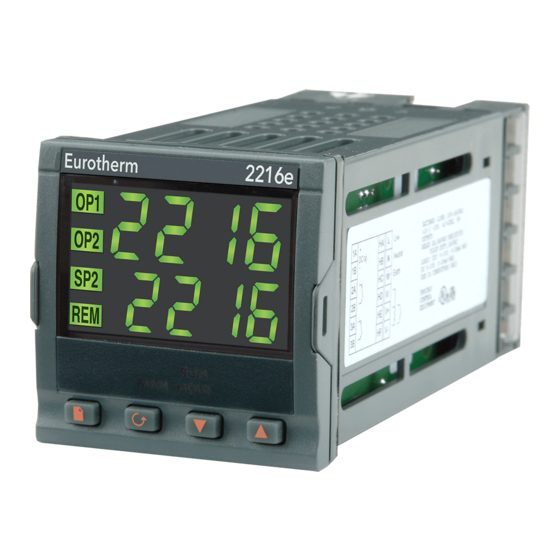
20.00 Upper readout 20.00 Lower readout Setpoint 2 active Remote Setpoint Setpoint rate limit Manual mode HOLD active Page Scroll Down Button Button Button Button Figure 1-1 Model 2216e front panel layout 2216e Controller Part Number HA026639 Issue 4 (CN22918) - Page 8 Press to decrease a value in the lower readout. Up button Press to increase a value in lower readout. Figure 1-2 Controller buttons and indicators ☺ For Valve Positioning, please refer to Appendix D ‘Motorised Valve Control Part Number HA026639 Issue 4 (CN22918) 2216e Controller...
-
Page 9: Getting Started
Installation and Operation Handbook Operation GETTING STARTED Thank you for selecting the 2216e controller. This section shows the principle of operation. 1.2.1 Viewing The Process Value and Setpoint Install and wire up the controller in accordance with Chapter 2 and switch on. Following a 3 second self-... -
Page 10: Viewing The Display Units
Actual output level % 100.0 3rd press Manual/Auto Actual state Auto Keep pressing to return to the Home display or select further parameters (if available) Figure 1-6 Upper readout is parameter name. Lower is value Part Number HA026639 Issue 4 (CN22918) 2216e Controller... -
Page 11: Use Of The 'Page' Button
☺ The actual list headings may be longer or shorter than indicated above and you can customise this for the operator’s convenience in EDIT level, Chapter 3. 2216e Controller Part Number HA026639 Issue 4 (CN22918) -
Page 12: Parameter Lists
If, at any time, no key is pressed within 45 seconds, the display will always return to the “HOME” display. A complete description of the parameter lists is given on page 1-14. Part Number HA026639 Issue 4 (CN22918) 2216e Controller... -
Page 13: Manual Or Automatic Control
140.0 1st press 2nd press Output Actual output level % 100.0 3rd press Manual/Auto to select automatic mode Auto manual mode Keep pressing to return to “HOME” display Figure 1-9 Auto/Manual select 2216e Controller Part Number HA026639 Issue 4 (CN22918) -
Page 14: How To Manually Adjust Output Power
To change the value (or state) of a parameter press the Raise button or the Lower button The remainder of this chapter provides a complete list of all parameters available. Part Number HA026639 Issue 4 (CN22918) 2216e Controller... -
Page 15: Setpoint 1 Or Setpoint 2
SSEL SSEL When setpoint 2 is selected the Press to change SP 1 SP2 beacon illuminates. between SP 1 and SP 2 Figure 1-11 To Select Setpoint 1 or 2 2216e Controller Part Number HA026639 Issue 4 (CN22918) -
Page 16: Ramp Dwell Function
The program will go into standby Press to choose the StbY The program will dwell for an rESt action required at the end of the dwell dwel unlimited period time Figure 1-12 Ramp/Dwell Program 1-10 Part Number HA026639 Issue 4 (CN22918) 2216e Controller... -
Page 17: To Run The Program
During Dwell. After return of power the working setpoint will servo to PV, the ramp continues to SP2 followed by full programmed dwell. In effect this causes the program to restart. ☺ Use the Hide, Reveal and Promote features to customise the display for a programmer. See Chapter 2216e Controller Part Number HA026639 Issue 4 (CN22918) -
Page 18: Location Of Parameters - Block Diagram
These are available in configuration level only triac /Invert output Logic Input Retrans-mission logic input on module 2 Functions Module 2 Retrans- listed in 2A Logic I/P mission configured) conf list Volts Figure 1-14 Controller Block Diagram 1-12 Part Number HA026639 Issue 4 (CN22918) 2216e Controller... -
Page 19: Navigation Diagram (Part A)
The navigation diagram shows a full list of possible parameters. However, some may not appear because they are dependent upon the particular controller variant. SP2.H End.t rset 100.0 Loc.L ProG rset 100.0 Loc.H StAt SPrr Figure 1.15a Navigation diagram 2216e Controller Part Number HA026639 Issue 4 (CN22918) 1-13... - Page 20 Complete lists or individual parameters normally hidden in Operator level. To see all the available parameters you must select Full level. See Chapter 3, Access Levels Only displayed when option selected Figure 1.15b Navigation diagram 1-14 Part Number HA026639 Issue 4 (CN22918) 2216e Controller...
-
Page 21: Parameter Tables
None readout of home display AmPS stat vPoS Customer ID 9999 Additional parameters may appear in the Home display if the ‘promote’ feature has been used (see Edit Level, Chapter 3). 2216e Controller Part Number HA026639 Issue 4 (CN22918) 1-15... -
Page 22: Alarm List
-dLo 9999 display Low current alarm Amps -Lcr -Hcr High current alarm Amps Hysteresis 9999 display Hy.EV Hysteresis for event 9999 alarms. See Note 1 display Loop break time 9999 secs 1-16 Part Number HA026639 Issue 4 (CN22918) 2216e Controller... -
Page 23: Autotune List
100.0 (appears when ti set to OFF) Cutback low Auto Auto 9999 as display Cutback high Auto Auto 9999 as display Relative cool gain rEL.C 1.00 1.00 0.01 9.99 (set 1) 2216e Controller Part Number HA026639 Issue 4 (CN22918) 1-17... -
Page 24: Setpoint List
Setpoint rate limit Units per minute dwEl Dwell time 0.1 to 999.9 minutes EnD.t End type rset rset hoLd Stby dwel ProG Program control rset rset rset Status of program Stat dwel 1-18 Part Number HA026639 Issue 4 (CN22918) 2216e Controller... -
Page 25: Input List
On/off list OnOf This set of parameters only appear if On/Off control has been configured hYS.H Heat hysteresis 9999 display hYS.C Cool hysteresis 9999 display HC.db Heat/Cool dead band 9999 display 2216e Controller Part Number HA026639 Issue 4 (CN22918) 1-19... -
Page 26: Output List
1.10.10 Access List Access list ACCS codE Full and Edit level 9999 password Goto Goto level OPEr OPEr OPEr conF OPEr FuLL Edit or conF ConF Configuration level 9999 password 1-20 Part Number HA026639 Issue 4 (CN22918) 2216e Controller... -
Page 27: Alarms
Setpoint (SP) Band Deviation Low Full Scale Low Rate of Change Output State Full scale Deviation Deviation high Deviation band Full scale high Rate of change Time Figure 1-16: Alarm Types 2216e Controller Part Number HA026639 Issue 4 (CN22918) 1-21... -
Page 28: Alarm Relay Output
Alarm 1 Relay Alarm 2 output Alarm 3 SEnS Input fail Sensor break Any combination of alarms can operate the relay. Typical alarms are shown Figure 1-17: Attaching Alarms to an Output 1-22 Part Number HA026639 Issue 4 (CN22918) 2216e Controller... -
Page 29: Setting Alarm Levels
4th press -Hcr High current Alarm 4 4--- to change 5th press Loop break time Lb t to change Press to return to list header Figure 1-18 To Set Alarm Trip Levels 2216e Controller Part Number HA026639 Issue 4 (CN22918) 1-23... -
Page 30: Alarm Indication And Acknowledgement
If a relay has been attached to the alarm output (see Chapter 7 ‘Alarm Operation’), it will operate when the alarm condition occurs and remain in the operated condition until the alarm is acknowledged AND it is no longer present 1-24 Part Number HA026639 Issue 4 (CN22918) 2216e Controller... -
Page 31: Diagnostic Alarms
This error message normally occurs when pre-configuring a no. io Modules are configured but controller without installing any of the required I/O modules not fitted Figure 1.19a Diagnostic alarms - continued on the next page 2216e Controller Part Number HA026639 Issue 4 (CN22918) 1-25... - Page 32 Acknowledge by pressing ‘page’ button and ‘scroll’ occurs button together. Figure 1.19b Diagnostic alarms *If the user has disassembled and reassembled the instrument, this error can occur if any connectors are not seated properly. 1-26 Part Number HA026639 Issue 4 (CN22918) 2216e Controller...
-
Page 33: Chapter 2 Installation
Installation and Operation Handbook Installation Chapter 2 INSTALLATION INSTRUMENT LAYOUT Display screen Latching ears Panel sealing gasket Panel retaining clips Label Sleeve Terminal covers Ratchets Figure 2-1: 2216e 1/16 DIN controller 2216e Controller... -
Page 34: Outline Dimensions Model 2216E
-0 +0.03 10mm 38mm Recommended (0.4in) (1.5in) minimum spacing of controllers (Not to scale) Figure 2-2: Outline dimensions Model 2216e controller The controller plugs into a plastic sleeve, which in turn fits into the panel cutout shown above. 2216e Controller... -
Page 35: Introduction
Installation and Operation Handbook Installation INTRODUCTION The Model 2216e is a precision temperature controller with self tuning. It has a modular hardware construction which provides two control outputs, one alarm relay and one communications port. 2.2.1 Controller Labels The labels on the sides of the controller identify the ordering code, the serial number, and the wiring connections. -
Page 36: Wiring
Ground* Output 2 Comms Output 3 Pt100 Figure 2-3: Model 2216e Wiring Connections * The ground connection is not required for electrical safety but must be connected to satisfy EMC requirements. 2.4.1 Wire Sizes All electrical connections are made to the screw terminals at the rear of the controller. They accept wire sizes from 0.5 to 1.5 mm... -
Page 37: Sensor Input Connections
PID Heating or cooling (18Vdc, 20mA max) output 2 *Logic can also be configured as logic input on module 2A. + PDS Mode 1 & 2 are only supported in Output 1. Figure 2-5: Outputs 1 and 2 connections 2216e Controller... -
Page 38: Pds Modes
When a relay contact is used in an alarm circuit ensure that the current passing through the snubber when the relay contact is open does not hold in low power electrical loads and thereby interfere with the failsafe operation of the alarm circuit 2216e Controller... -
Page 39: Typical Single Loop Wiring Diagram
TE10 Cooling Heater solenoid valve Thermocouple Figure 2-6: Typical wiring diagram, Model 2216e Controller Safety requirements for permanently connected equipment state: • A switch or circuit breaker shall be included in the building installation • It shall be in close proximity to the equipment and within easy reach of the operator •... -
Page 40: Logic Drive Fan Out
EIA-232 serial communications Do not use Do not use Common PDS Setpoint input (SST) Not used Not used Not used Signal Common A (+) B (-) 2-wire EIA-485 Serial Not used Not used Common Communications Figure 2-7: Communication connections 2216e Controller... -
Page 41: Wiring Of Eia-485 Serial Communication Links
Series 2000™ Controller Note: All termination resistors are 220 ohm 1/4W carbon composition. Local grounds are at equipotential. Where equipotential is not available wire into separate zones using a galvanic isolator. Figure 2-8: 2-wire EIA-485 wiring 2216e Controller... -
Page 42: Devicenet Wiring To Series 2200E Controllers
Installation Installation and Operation Handbook 2.10 DEVICENET WIRING TO SERIES 2200E CONTROLLERS This section covers the DeviceNet digital communications option for the model 2216e PID controller. To configure DeviceNet communications refer to section 5.9. 2.10.1 DeviceNet Terminal Functions Series 2200e... -
Page 43: Wiring Interconnections For Devicenet Communications
Address 12 2200e Controller Network Supply 24Vdc ( +1%) 250mV p-p Ripple 121 (SLAVE) Address N+1 Daisy chain to further Fit to last instrument in the instruments chain Figure 2-9: Wiring Connections for 2200e Series DeviceNet Controllers 2216e Controller 2-11... - Page 44 Installation Installation and Operation Handbook 2-12 2216e Controller...
-
Page 45: Chapter 3 Access Levels
You can also promote parameters to the home list. (See Edit level at the end of the chapter). Configuration ConF This special level allows access to set up the fundamental characteristics of the controller. Figure 3-1 Access levels 2216e Controller... -
Page 46: Selecting An Access Level
(If an incorrect password has been entered and the controller is still ‘locked’ then pressing Scroll at this point will simply return you to the aCCs list header.) Note: From this code display, you can access “read only” configuration level by pressing together. To escape, press together 2216e Controller... -
Page 47: Level Selection
Chapter 5, Configuration Press the Scroll button 3.2.5 Configuration level The first display of configuration is shown. See chapter 5, Configuration for details of the configuration parameters. inSt For instructions on leaving configuration level see Chapter 5, Configuration. ConF 2216e Controller... -
Page 48: Returning To Operator Level
Scroll through the lists to the required parameter and choose the ‘Pro’ code. The parameter is then automatically added (promoted) into the Home display list (the parameter will also be accessible as normal from the standard lists. a maximum of 12 parameters can be promoted. Promoted parameters are automatically ‘alterable’. 2216e Controller... -
Page 49: Chapter 4 Tuning
Relative cool Only present if cooling has been configured. Sets the cooling proportional rEL.C gain band by dividing the Pb value by the rEL.C value. Table 4-1 Tuning parameters 2216e Controller... -
Page 50: Automatic Tuning
This method automatically determines the value of the parameters listed in table 4-1 on the previous page. The 2216e uses a ‘one-shot’ tuner which works by switching the output on and off to induce an oscillation in the measured value. From the amplitude and period of the oscillation, it calculates the tuning parameter values. -
Page 51: How To Tune
(for example, under startup conditions). If either low cutback or high cutback is set to ‘Auto’ the values will be fixed at three times the proportional band, and will not be changed during automatic tuning. 2216e Controller... -
Page 52: Manual Tuning
Set the Pb, ti, td parameter values according to the calculations given in Table 4-2. Type of control Proportional Integral time ‘ti’ Derivative time band ‘Pb’ ‘td’ Proportional only P + I control 2.2xB 0.8xT P + I + D control 1.7xB 0.5xT 0.12xT Table 4-2 Tuning values 2216e Controller... -
Page 53: Setting The Cutback Values
In example (a) increase Lcb by the overshoot value. In example (b) reduce Lcb by the undershoot value. Example (a) Temperature Setpoint Overshoot Example (b) Temperature Undershoot Time Where the temperature approaches setpoint from above, you can set Hcb in a similar manner. 2216e Controller... -
Page 54: Integrating Action And Manual Reset
Adc to ‘CALC’. The controller will then calculate a new value for manual reset, and switch Adc to ‘mAn’. Adc can be repeated as often as you require but between each adjustment you must allow time for the temperature to stabilise. 2216e Controller... -
Page 55: Chapter 5 Configuration
It is the responsibility of the person commissioning the process to ensure that the configuration is correct Whenever the configuration level is accessed, all controller outputs are held in the power off state and control operation is suspended 2216e Controller... -
Page 56: Selecting Configuration Level
ConF (factory default = 2) ConF PASS At this point the controller is in 4th press configuration level InSt ConF ConF Repeated pressing of “Page” button selects configuration list headings in a continuous loop. Figure 5.1 2216e Controller... -
Page 57: Selecting A Configuration Parameter
They are grouped under headings. The actual parameters shown in your controller may differ slightly since some appear only as a result of selecting others. A full list of possibilities is included in the PARAMETER TABLES which follow the navigation diagram. 2216e Controller... -
Page 58: Navigation Diagram (Part A)
Input Config. - selects the input sensor type Sbr.t Ltch Sb.OP Auto User cal. Config. - to calibrate to external reference sources AL 4 LC.Hi Alarms Config. - sets up the alarm types BLoc Ltch Fig 5.4a Navigation Diagram (Part A) 2216e Controller... -
Page 59: Navigation Diagram (Part B)
Sets up the output 2 module 2A & 2B 2A Conf 3A Conf Sets up the action of the relay on output 4 3A to 3C To choose new passwords Pass Conf Exit Conf To leave configuration level and return to operator level 2216e Controller... -
Page 60: Configuration Parameter Tables
Freeze output (maintains output at value HoLd immediately before break) LC.Hi Load current scaling factor See Chapter 9 ☺ Factory default parameter values and states are included where applicable and are indicated by the shaded areas in the following tables. 2216e Controller... - Page 61 Sensor break detection is disabled trip level Appears for mV or V inputs only Auto Trip level set by the sensor input table Trip level set at 7.5KΩ HiHi Trip level set at 15KΩ (must be selected when voLt input is enabled) 2216e Controller...
- Page 62 ‘Pnt.H’. This value is automatically calculated when performing a high point calibration. *If User calibration is enabled, then the User calibration parameters will appear in the Input list of Operator Full access level. See Chapter 6, User calibration. 2216e Controller...
- Page 63 (1) Blocking allows the alarm to become active only after it has first entered a safe state. These are ‘soft’ alarms ie. Indication only. They would normally be attached to an output. See Chapter 7 for a step by step guide. 2216e Controller...
- Page 64 No parity Prty Even parity EvEn Odd parity Comms Resolution FuLL Full resolution RESn Integer resolution Note 1: 1200 baud rate not supported by EIBisynch Note 2: Not used with some communication protocols. Please consult factory. 5-10 2216e Controller...
- Page 65 Normal (e.g. heating and cooling) SEnS Inverted (alarms - de-energise in alarm) DC output scaling For id = dC.OP the following parameters appear Out.L DC output minimum 0mA to ‘Out.H’ Out.H DC output maximum ‘Out.L’ to 20mA 2216e Controller 5-11...
- Page 66 * In place of the dashes, the last three characters indicate the alarm type as per table A in the AL list: eg 1FSL = Full Scale Low If an alarm is not configured the displayed name will differ: e.g. ‘AL 1’ will be shown, for the first alarm 5-12 2216e Controller...
- Page 67 As per output 2A configuration Password list PASS FuLL or Edit level password (default = 1) ACC.P Configuration level Password (default = 2) cnF.P Note:- When passwords are changed please make a note of the new numbers Exit Exit Configuration 2216e Controller 5-13...
-
Page 68: Configuration Of Digital Communications
Baud Rate. The choices are:- 1200. 2400, 4800, 9600, 19,200 for Modbus and EI-Bisynch 125(K), 250(K), or 500(K) for DeviceNet Parity and Resolution can be set by the same procedure. These will normally be set to None and Full respectively. 5-14 2216e Controller... -
Page 69: To Set Instrument Address
The EDS (Electronic Data Sheet) file for the Series 2200e is named 2K2DN.EDS and is available from your supplier, or electronically by going to Web site (www.eurotherm.com). The EDS file is designed to automate the DeviceNet network configuration process by precisely defining vendor-specific and required device parameter information. - Page 70 Installation and Operation Handbook Configuration 5-16 2216e Controller...
-
Page 71: Chapter 6 User Calibration
User calibration works by introducing zero and span offsets onto the factory set calibration. The factory set calibration can always be retrieved. To understand how to select and change parameters in this chapter you will need to have read Chapter 2 - Operation, Chapter 3- Access Levels and Chapter 5 - Configuration. 2216e Controller... -
Page 72: User Calibration Enable
‘CAL conf list Press Press the Scroll button until you reach User calibration enable to select: YES: Calibration enable Calibration disabled Press together to go to the Exit display Exit Exit configuration to select ‘YES’ and return to Operator level. 2216e Controller... -
Page 73: Single Point Calibration
Selecting ‘USEr’ will reinstate any previously set User calibration and make available the User parameters, as follows: Press the Scroll button Calibrate low point? CAL.S to select ‘YES’ Selecting ‘no’ will hide the next parameter Press the Scroll button continued on the next page 2216e Controller... -
Page 74: Two Point Calibration
Set the process under calibration such that the known reference exhibits the required higher Process Value (temperature) and allow to stabilise. Press the Scroll button to obtain the high calibration point as shown in the following diagrams. 2216e Controller... -
Page 75: Calibration Points And Calibration Offsets
‘AdJ.H’ (adjust high calibration). OFS.L Low point calibration offset Offset, in display units, at the user low calibration point ‘Pnt.L OFS.H High point calibration offset Offset, in display units, at the user high calibration point ‘Pnt.H’. 2216e Controller... - Page 76 User Calibration Installation and Operation Handbook 2216e Controller...
-
Page 77: Chapter 7 Alarm Configuration
7.1.1 Types Of Alarms The use of alarms in the 2216e controller is extremely versatile. Up to 4 alarms can be configured. Any combination of these 4 alarms can be attached to any one or more outputs, or any number of the available “soft” alarms can be combined to operate a single output. - Page 78 Alarm occurs after it has been through a start up phase not in alarm condition. Sense Of Output Relay energised or de-energised in alarm condition. See also sections 1-12 and 7.4. Soft Alarms Indication only and do not operate an output. See also Section 1.11 for further information on alarm types. 2216e Controller...
-
Page 79: Digital Output Functions
Chapter 9 Program END Signals the end of a program New Alarm Signals a new alarm The Sense of the Output can be set to relay energised or de-energised in the alarm condition for any of the above functions. 2216e Controller... -
Page 80: Step1 - Configuring The Four 'Soft' Alarms
1 latching or Hcr High current non-latching Ltch Choices No/Auto/Man Press Press “SCROLL” key to choose alarm 1 blocking bLoc Choices Yes/No Press Press “SCROLL” key to repeat for alarms 2 - 4 to return to list header Figure 7.1 2216e Controller... -
Page 81: Step 2 - Attaching An Alarm To A Physical Output
DiGF indicating that it has been added to the output, i.e., 3F.S.H. noch 3FSH Figure 7.2 to select: SEnS inverted (relay de-energised in alarm) direct (relay energised in alarm) Keep pressing “SCROLL” button to return to list header 2216e Controller... -
Page 82: Step 3 - Grouping Alarms On A Single Output
STEP 3 - GROUPING ALARMS ON A SINGLE OUTPUT In the previous example one alarm condition is allocated to one output relay. The 2216e controller allows alarms and events to be grouped on to a single output. These events are shown in the table below. -
Page 83: Chapter 8 Motorised Valve Control
MOTORISED VALVE CONTROL PARAMETERS FOR MOTORISED VALVE CONTROL The 2216e can be configured for motorised valve control as an alternative to the standard PID control algorithm. This algorithm is designed specifically for positioning motorised valves. The motorised valve algorithm operates in the boundless mode, which does not require a position feedback potentiometer for control purposes. -
Page 84: Motorised Valve Applications
Table 8-2 Valve Positioner Set-up Table The following operating parameters do not effect the 2200e when the valve positioner option has been configured: CYC.H Heat Cycle Time CYC.C Cool Cycle Time ont.C Minimum on time for cooling 2216e Controller... -
Page 85: Chapter 9 Load Current Monitoring And Diagnostics
Typically used where element bunching may exceeds a set limit occur SSR short circuit This will apply full power to the heaters which could result in an over temperature condition. This alarm provides early warning. Heater failure Indicates open circuit load conditions 2216e Controller... -
Page 86: Example Wiring Diagram (Mode 1 & 2 Operation)
1. SSR type TE10/PDS2 OR 2. Intelligent current transformer type PD/CTX + contactor or zero voltage switching SSR 2216e controller configured for PDS mode 2 option using logic output. This module must be fitted in module position 1. (order code M2). -
Page 87: Operation
SSR RMS On State Current This is the default state when high or low current alarms are configured. The load current displayed is the steady state true rms current measured during the ON period. The minimum on time is:- Mode 2 0.1second 2216e Controller... -
Page 88: How Heater Alarms Are Displayed
They appear for mode 2 operation only. Htr.F Heater Fail No current is being drawn while the controller output demand signal is on SSr.F SSR Fail The load is continuously on while the controller output demand signal is off 2216e Controller... -
Page 89: To Set The Alarm Trip Levels
Any plug in module can be used for alarms provided they are not already being used for another purpose , such as control. Any one or more alarms can be attached to an output, which will operate when an alarm occurs. Contacts are rated at 2A 264Vac for operating external beacons or audible devices. 2216e Controller... -
Page 90: To Configure Pds Load Current Diagnostics
Func The module function is SSr1 Press set to PDS mode 1 to show SSr1 or SSr 2 as required. This sets the output Press to show signal to normal for SEnS SEnS heating control Press show nor 2216e Controller... -
Page 91: To Configure Low And High Current Trip Alarms
AL2 blink to show the alarm (alarm 2) appears type has been accepted To make alarm 2 = High Press Current show HCr Note:- The above alarms are known as SOFT ALARMS because they are indication only. 2216e Controller... -
Page 92: To Attach Soft Alarms To A Relay Output
Ht.r.F SS.r.F etc until CLr appears in the lower display. This will To remove alarms from an output press clear all alarms attached to this output. Alarms Connected to a Relay Output Soft Alarms SEnS Output Module 2216e Controller... -
Page 93: The Scaling Factor
Scalar = 100/N Where N = Turns through PDCTX Scalar Scalar Maximum Resolvable Current TE10 Determined by the maximum range of the SSR PDCTX 100A (or 100 ampere turns) Finally Exit configuration level. See Chapter 5 2216e Controller... - Page 94 Load Current Monitoring and Diagnostics Installation and Operation Handbook 9-10 2216e Controller...
-
Page 95: Chapter 10 Retransmission
1. Process Variable 2. Setpoint 3. Error 4. Control Output The retransmission signal is available as 0-20mA, 4-20mA, 0-5V, 1-5V or 0-10V and is connected to terminals 1A and 1B when module 1A is fitted as a DC module. 2216e Controller 10-1... -
Page 96: To Configure Retransmission
HEAT Press COOL Cool control output select the parameter for Retransmission retransmission Output demand Process Variable Error Setpoint (working) Press to show If Func is a SEns retransmission SEnS parameter the value of Sens has no effect. 10-2 2216e Controller... -
Page 97: Scaling Retransmitted Output Signals
10.3.1 To Range Retransmitted Output OP For output of 0-100% = 0-20mA set Out.H to 20.0 and Out.L to 0.0 % Output For output of 0-100% = 4-20mA set Out.H to 20.0 and Out.L to 4.0 OUT.L OUT.H 2216e Controller 10-3... -
Page 98: To Range Retransmitted Setpoint Sp Or Process Variable Pv
As above but rnG.L = -10 and rnG.H = 400 Retransmitted Value 0mA for an error of -10 0.0487mA for an error of 0 20mA for an error of +400 Note: To read a negative error it is necessary to set rnG.L to a negative limit 10-4 2216e Controller... -
Page 99: Appendix A Understanding The Ordering Code
Order Code Appendix A UNDERSTANDING THE ORDERING CODE The 2216e controller has a modular hardware construction with the option of three outputs and one communications port. The ordering code is in two parts: the hardware code followed by the software code. The hardware code specifies the hardware build of the controller, and the software code the software configuration. - Page 100 0-20mA PID cooling PV retrans EI-Bisynch 4-20mA PID cooling Setpoint retrans 2-wire RS485 DC Retrans. (isolated) 4-wire RS422 Output retrans Select from table A RS232 Error retrans Second character DeviceNet 0-20mA DeviceNet 4-20mA PDS Input 0-5V Setpoint 1-5V 0-10V 11-2 2216e Controller...
- Page 101 3272 Exergen K80 IR pyrometer Process inputs -9.99 to +80.00mV -999 9999 0 to 20mA -999 9999 4 to 20ma -999 9999 0 to 5Vdc -999 9999 1 to 5Vdc -999 9999 0 to 10Vdc -999 9999 2216e Controller 11-3...
- Page 102 Setpoint limits: Include the decimal position required in the displayed value – up to one for temperature inputs, up to two for process inputs An external 1% current sense resistor is supplied as standard. If greater accuracy is required, a 0.1% 2.49Ω can be ordered as part number SUB2K/249R.1. 11-4 2216e Controller...
-
Page 103: Appendix B Safety And Emc Information
When the controller is removed from its sleeve, some of the exposed electronic components are vulnerable to damage by electrostatic discharge from someone handling the controller. To avoid this, before handling the unplugged controller discharge yourself to ground. 2216e Controller 12-1... -
Page 104: Installation Safety Requirements
Only use copper conductors for connections, (except thermocouple). Ensure that the wiring of installations comply with all local wiring regulations. For example in the in the UK, use the latest version of the IEE wiring regulations, (BS7671). In the USA, use NEC Class 1 wiring methods. 12-2 2216e Controller... - Page 105 In some installations it is common practice to replace the temperature sensor while the controller is still powered up. Under these conditions, as additional protection against electric shock, we recommend that the shield of the temperature sensor is grounded. Do not rely on grounding through the framework of the machine. 2216e Controller 12-3...
- Page 106 (or could carry, under fault conditions) hazardous voltages*, double insulation should be used. * A full definition of ‘Hazardous’ voltages appears under ‘Hazardous Live’ in BS EN61010. Briefly, under normal operating conditions Hazardous voltage levels are defined as >30V RMS (42.2V peak) or >60V dc. 12-4 2216e Controller...
- Page 107 PDS mode 2: SSRx Enhanced Load Doctor™ logic heating with load/SSC failure alarms and load current display Triac Rating 1A, 30 to 264Vac resistive Application Heating or cooling Analog Range Isolated, 0 to 20mA 0 to 10Vdc (configurable between limits) Application Heating or cooling 2216e Controller 12-5...
-
Page 108: Control Functions
Category II Atmospheres Electrically conductive pollution must be excluded from the cabinet in which this controller is mounted. This product is not suitable for use above 6,562ft (2000m) or in corrosive or explosive atmospheres without further protection. 12-6 2216e Controller... -
Page 109: Appendix C Rohs
Indicates that this toxic or hazardous substance contained in at least one of the homogeneous materials used for this part is above the limit requirement in SJ/T11363-2006. Approval Name: Position: Signature: Date: Martin Greenhalgh Quality Manager IA029470U460 (CN23172) Issue 1 Feb 07 2216e Controller 13-1... - Page 110 RoHS Installation and Operation Handbook 13-2 2216e Controller...
- Page 112 The specifications in this document may therefore be changed without notice. The information in this document is given in good faith, but is intended for guidance only. Eurotherm Limited will accept no responsibility for any losses arising from errors in this document.
Need help?
Do you have a question about the 2216e and is the answer not in the manual?
Questions and answers