
Related Manuals for Scout Boats 295 Abaco


Summary of Contents for Scout Boats 295 Abaco
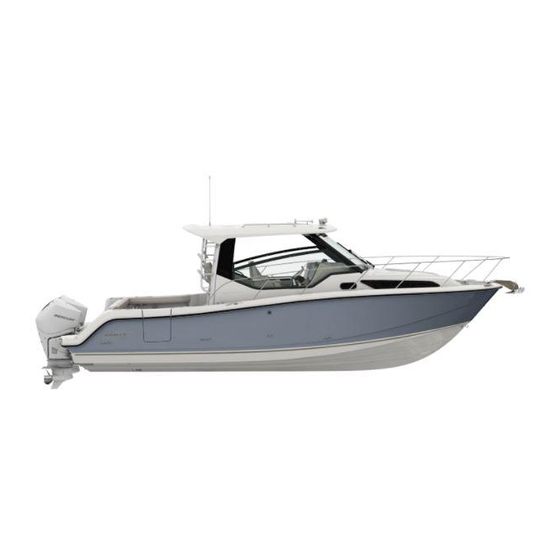
- Page 1 295 Abaco Owner’s Manual Scout Boats Inc. 2531 Hwy 78 West Summerville, SC 29483...
- Page 2 THIS PAGE WAS LEFT BLANK INTENTIONALLY Print Date 4-2008...
-
Page 3: Safety Information
SAFETY INFORMATION Your Scout manual has been written to include a number of safety instructions to assure the safe operation and maintenance of your boat. These instructions are in the form of DANGER, WARNING, CAUTION, and NOTICE statements. The follow- ing definitions apply: HAZARDS OR UNSAFE PRACTICES WHICH COULD RESULT IN MINOR PERSONAL INJURY... - Page 4 THIS PAGE WAS LEFT BLANK INTENTIONALLY...
-
Page 5: Boat Information
PROPELLERS MAKE: BLADES: DIAMETER/PITCH: SHAFT: AIR CONDITIONER MAKE: MODEL: SERIAL #: BTU OUTPUT: DEALER SCOUT BOATS NAME: PHONE: DEALER/PHONE: REPRESENTATIVE: SALESMAN: ADDRESS: SERVICE MANAGER: ADDRESS: SCOUT E-MAIL DEALER E-MAIL: Scout reserves the right to make changes and improvements in equipment, design and vendored equipment... - Page 6 THIS PAGE WAS LEFT BLANK INTENTIONALLY...
-
Page 7: Certifications & Specifications
To be in compliance with European directives for recreational boats as published by the International Organization for Standardization (ISO) in effect at the time this boat was manufactured, we are providing the following information. Manufacturer: Scout Boats Name: 2531 Hwy 78 West... -
Page 8: Scout Warranty
(7) Any Scout Boat sold to a customer, (who happens to be the original owner), by anyone other than an authorized Scout Boats, Inc. dealer. (8) Any Scout Boat that has been used on a trailer that does not adequately support the hull or any trailer that may be considered undersized, including any and all roller type trailers. - Page 9 Scout Boats, Inc. within 10 days of sale of his/her boat to the new owner. A notarized bill of sale and a $100 administration fee payable to Scout Boats, Inc.
- Page 10 THIS PAGE WAS LEFT BLANK INTENTIONALLY...
-
Page 11: Owner's / Operator's Information
All warranty repairs must be performed by an authorized taken place. After which, the transferee will be treated as the original purchaser as outlined in the Scout Boats Limited Scout Dealer. Should a problem develop that is related to faulty workmanship or materials, as stated in the Limited... - Page 12 • If you are away from home, or your selling dealer is not Yamaha Engine Warranty an authorized Yamaha dealer, use the following toll-free Yamaha is ready to stand behind your purchase with strong numbers to find the nearest Yamaha dealer. warranty coverage.
-
Page 13: Table Of Contents
TABLE OF CONTENTS SAFETY INFORMATION ................................3 BOAT INFORMATION ................................. 5 CERTIFICATIONS & SPECIFICATIONS ........................... 7 SCOUT WARRANTY ..................................8 OWNER’S / OPERATOR’S INFORMATION ..........................11 Chapter 1: PROPULSION SYSTEM 1.1 General ....................................17 1.2 Drive System Corrosion ............................... 17 1.3 Engine Lubrication ................................ - Page 14 TABLE OF CONTENTS Chapter 5: FRESH WATER SYSTEM 5.1 General ....................................45 5.2 Fresh Water System Operation ............................. 45 5.3 Water Heater ..................................45 5.4 Shower Operation ................................46 5.5 Fresh Water System Maintenance ............................46 Chapter 6: RAW WATER SYSTEM 6.1 General ....................................
- Page 15 TABLE OF CONTENTS Chapter 10: INTERIOR EQUIPMENT (continued) 10.3 Air Conditioner (Optional) ..............................73 10.4 Cabin Woodwork ................................74 Chapter 11: SAFETY EQUIPMENT 11.1 General ....................................75 11.2 Engine Alarms ..................................75 11.3 Neutral Safety Switch ................................. 75 11.4 Engine Stop Switch ................................75 11.5 Required Safety Equipment ..............................
- Page 16 TABLE OF CONTENTS Appendix A: SCHEMATICS DC Power Layout ..................................103 DC Power - Battery Cable Layout ............................104 DC Power - Battery Cable Kit ..............................105 DC Power - Battery Switch Panel ............................. 106 DC Power - Battery Switch Panel Wiring Detail ........................107 DC Power - Main Harness Layout ............................
-
Page 17: Chapter 1: Propulsion System
Chapter 1: PROPULSION SYSTEM General Your Scout is designed to be powered with 2-cycle or 4-cycle outboard motors. 4-cycle outboard engines do not use an oil injection system and are not equipped with remote oil tanks. They have an oil sump in the crankcase that must be kept full of the type of oil recommended by the engine manufacturer. -
Page 18: Engine Lubrication
Engine Lubrication 2-cycle outboard motors are lubricated by a variable ratio oil injection system. The oil tanks are mounted below the cockpit floor near the transom. Always monitor the oil level before each cruise by checking the gauge or indicator lights in the helm (not available on all engine installations) or visually checking the oil level using the reference marks on the tank. -
Page 19: Engine Instrumentation
Yamaha tachometers also contain the engine trim meter, oil level or oil pressure indicator, water pressure and the overheat Note: Most Scout boats are equipped with Yamaha warning indicator. engines and multifunction instruments. A brief description of those instruments and their function is listed in this section. - Page 20 Speedometer Engine Alarms The speedometer indicates the speed of the boat in miles per All outboards are equipped with an audible alarm system hour. Most speedometers measure the water pressure against a mounted in the helm area that monitors selected critical engine small hole in a pickup tube located in the engine lower unit or systems.
-
Page 21: Chapter 2: Helm Control Systems
Chapter 2: HELM CONTROL SYSTEMS General The helm controls consist of three systems: the engine throttle and shift controls, the steering system, and the trim tab control switches. These systems provide the operator with the ability to control the direction and attitude of the boat from the helm station. -
Page 22: Engine Power Tilt And Trim
Repeat this test with the shift levers in reverse and the engine the engines tilted. Never leave the transom access open when throttles at idle. Again, the starter should not engage for either the boat is underway and always make sure the wave gate is engine. -
Page 23: Steering System
Steering System Power Assist Hydraulic Steering The steering system on your boat is power assisted and com- prised of two circuits: a manual system, which is the control element, and a hydraulic power pump, which is the working element. The manual system is hydraulic and made of three main com- ponents: the helm assembly, hydraulic hoses and a hydraulic steering cylinder. -
Page 24: Control Systems Maintenance
Before leaving the dock, make sure that the tabs are in the full “UP” position by holding the control in the bow up position for ten (10) seconds. Always establish the intended heading and cruise speed before attempting to adjust the hull attitude with the trim tabs. After stabilizing speed and direction, move the trim tabs to achieve a level side to side running attitude being careful not to over trim. - Page 25 bottom paint will damage the O-ring seals when the ram is When new, or after repairs, hydraulic steering systems may retracted and allow sea water to enter the actuator motor. need to have all air purged from the system. Check the steering fluid level in the helm, it should be maintained at no less than Contact your dealer or the trim tab manufacturer for information 1/2”...
- Page 26 THIS PAGE WAS LEFT BLANK INTENTIONALLY...
-
Page 27: Chapter 3: Fuel System
Chapter 3: FUEL SYSTEM General The gasoline fuel system used in Scout boats is designed to meet or exceed the requirements of the U.S. Coast Guard, the Boating Industry Association, and The American Boat and Yacht Council in effect at the time of manufacture. -
Page 28: Diesel Generator Fuel System (Optional)
the rear fuel fill on the port gunnel. The auxiliary fuel tank is located forward of the main tank and filled by the forward fuel fill on the port gunnel. Each fuel withdrawal line is equipped with an anti-siphon valve where the line attaches to the fuel tank. -
Page 29: Fueling Instructions
Important: Do not allow the generator to sit unused for an extended period with the fuel tank less than full. Changes in temperature and weather conditions can cause con- densation in diesel fuel tanks that are less than 3/4 full. Diesel Fuel Filters The diesel fuel filter is installed near the generator. -
Page 30: Fuel System Maintenance
The fuel vent screen should be clear and free from corrosion and STATIC ELECTRICITY CAN BE GENERATED WHILE salt buildup. The screen will prevent insects and other foreign FUELING AND CAN CAUSE A FIRE OR EXPLOSION. matter from contaminating the fuel and fuel system. The fuel TO PREVENT STATIC SPARKS WHEN FILLING THE vent should be replaced if the vent or screen is damaged or badly TANK, MAKE SURE THE NOZZLE IS IN CONTACT... - Page 31 in fuel and water drained from the filter. Severe cases of algae will produce a black jelly like substance that quickly clogs the filters and starves the engine for fuel. DO NOT DRAIN ANY FUEL INTO THE BILGE WHEN SERVICING THE FUEL SYSTEM. THIS COULD LEAD TO A FIRE OR EXPLOSION.
- Page 32 THIS PAGE WAS LEFT BLANK INTENTIONALLY...
-
Page 33: Chapter 4: Electrical System
Chapter 4: ELECTRICAL SYSTEM General Your Scout is equipped with 120-volt AC and 12-volt DC electrical systems. The AC system can draw current from one of two sources, either shore power outlets at dock side or the optional generator. The DC system draws current from on board batteries. - Page 34 starting problems and damage to the DC charging systems. You also should not mix the size or brand of the wet cell batteries. Always consult your Scout dealer before changing the type of batteries in your boat. Your boat has provision for four batteries. One for each engine and two batteries in parallel for the house and accessory circuits.
- Page 35 connected. This pump will run as needed whenever the water in the bilge accumulates high enough to raise the float switch to the “ON” position and turn off when the water is removed. Fwd Bilge Manually activates the forward bilge pump located in the for- ward bilge below the floor grate in the cabin.
- Page 36 are located in the panel near the switches. An LED light built into the toggle switches indicate that the circuit is activated. Courtesy Lights Activates the overhead lights in the hardtop that illuminate the bridge deck. Aft Spreader Lights Activates the overhead lights at the rear of the hardtop that illuminate the cockpit.
- Page 37 Radio Supplies 12-volt electrical current to the stereo and optional CD player. Cabin Lights Supplies 12-volt electrical current to the cabin light switches. Refrigerator Supplies 12-volt electrical current directly to the refrigerator. Water System Supplies 12-volt electrical current directly to the freshwater pump pressure switch located on the pump.
-
Page 38: 120-Volt Ac Electrical System
120-Volt AC Electrical System The AC electrical system is supplied 120-volt, 60 cycle cur- rent by a shore power outlet at dockside. It is wired totally separate from the 12-volt DC system and is equipped with an onboard isolation system. All AC current is distributed to the accessories through individual circuit breakers located in the AC panel. - Page 39 Disconnecting procedure for shore power connection: Turn the main breaker on the AC panel to the “OFF” posi- tion. Turn the disconnect breaker on the dockside outlet to the “OFF” position. Disconnect the cable from the dockside outlet and replace the outlet caps.
-
Page 40: Generator (Optional)
Note: All AC electrical outlets are provided with ground fault interrupts to protect against electric shock. These outlets should be tested periodically to en- sure proper operation by pressing the test/reset buttons in the center of faceplate. GFI outlets do not protect against short circuits and overloads. -
Page 41: Bonding System And Galvanic Isolator
The seawater cooling system includes a strainer that prevents Bonding System and debris in the seawater from entering the cooling pump. The Galvanic Isolator strainer is located in the bilge compartment bilge near the Your boat is equipped with a bonding system that interconnects generator. - Page 42 Inspect all wiring for proper support, sound insulation, and Inspect all wiring for proper support, sound insulation, tight terminals, paying particular attention to portable appli- and tight terminals, paying particular attention to portable ance cords and plugs. appliance cords and plugs. Check all below deck wiring to be sure it is properly supported, The entire AC circuitry, especially the shore power cords, should that the insulation is sound, and that there are no loose or cor-...
-
Page 43: Ac Line Load Estimator
AC Line Load Estimator electrical load on each circuit. An owner’s manual for each AC accessory installed on your boat at the factory has been Depending on the AC power load your boat requires and included with your boat. Additionally, you should make the power available from the shore supply or the generator, sure you have the manuals for accessories installed by your you may not be able to operate all 120-volt AC accessories... - Page 44 THIS PAGE WAS LEFT BLANK INTENTIONALLY...
-
Page 45: Chapter 5: Fresh Water System
Chapter 5: FRESH WATER SYSTEM General The fresh water system consists of a potable water tank, dis- tribution lines and a distribution pump. The pump is equipped with an automatic pressure switch and is located near the water tank. The tank is below the aft berth in the cabin and filled through a labeled deck plate located on the port side of the cockpit near the tackle station. -
Page 46: Shower Operation
Do not supply current to an empty water heater. Damage to the heater will result. The system must be filled and primed before using the water heater. Shower Operation There is a shower located in the head compartment. The head shower has hot and cold water and a retractable shower head with an on/off valve. - Page 47 • The batteries must be properly maintained and charged. • Make a chlorine solution by mixing two ounces of Operating the pressure pump from a battery with a low household chlorine bleach in a gallon of water. This charge could lead to pump failure. mixture will treat approximately fifteen gallons.
- Page 48 THIS PAGE WAS LEFT BLANK INTENTIONALLY...
-
Page 49: Chapter 6: Raw Water System
Chapter 6: RAW WATER SYSTEM General In the raw or sea water systems, the baitwell water pump is mounted to a sea cock on the thru-hull fitting located in the stern bilge compartment. The water system pressure pump, air conditioner pump and generator cooling pump are connected to individual thru-hull valves. -
Page 50: Baitwell
The Washdown Pump Connector A quick-release raw water washdown hose connector is lo- cated on the starboard side of the cockpit near the baitwell. It is identified by a black plastic cover that opens to access the connector fitting. The connector fitting has an automatic valve that is always closed until the washdown hose is connected. -
Page 51: Raw Water System Maintenance
Raw Water System Maintenance SHOULD A HOSE RUPTURE, TURN THE PUMP OFF The following items should be done routinely to help maintain IMMEDIATELY. ALWAYS CLOSE THE THRU-HULL your raw water system: VALVE WHEN PERFORMING MAINTENANCE ON A SEA WATER PUMP. •... - Page 52 THIS PAGE WAS LEFT BLANK INTENTIONALLY...
-
Page 53: Chapter 7: Drainage Systems
Chapter 7: DRAINAGE SYSTEMS General All water is drained by gravity to overboard thru hull fittings located in the hull above the water line. It is important to check the drain system frequently to insure it is free flowing and that the hoses on the thru hull fittings are secure and not leaking. -
Page 54: Cockpit And Deck Drains
THE FEDERAL WATER POLLUTION CONTROL ACT PROHIBITS THE DISCHARGE OF OIL OR OILY WASTE INTO OR UPON THE NAVIGABLE WATERS OF THE UNITED STATES OR THE WATERS OF THE CONTIGUOUS ZONE IF SUCH DISCHARGE CAUSES A FILM OR SHEEN UPON, OR A DISCOLORATION OF THE SURFACE OF THE WATER, OR CAUSES A SLUDGE OR EMULSION BENEATH THE SURFACE OF THE WATER. - Page 55 • • Frequently test the automatic bilge pump switches for Clean and flush the fishboxes, coolers and storage boxes proper operation. This is accomplished by lifting the float with soap or a bilge cleaner and fresh water after each use switch until the pump is activated.
- Page 56 THIS PAGE WAS LEFT BLANK INTENTIONALLY...
-
Page 57: Chapter 8: Ventilation System
Chapter 8: VENTILATION SYSTEM Cabin and Bridge Deck Ventilation Ventilation to the cabin area is provided by a deck hatch and three opening port windows. There are also two small deck hatches in the hardtop that provide ventilation for the bridge deck. -
Page 58: Carbon Monoxide And Proper Ventilation
Carbon Monoxide and of equipment. Never rely on alarm systems to save your life, common sense is still prudent and necessary. Remember, the Proper Ventilation operator of the boat carries the ultimate responsibility to make sure the boat is properly ventilated and the passengers are not exposed to dangerous levels of carbon monoxide. -
Page 59: Maintenance
Maintenance • Periodically lubricate all hinges and latch assemblies with a light oil. • Periodically clean and coat gasket materials with silicone to help keep them pliable. • The opening cabin deck hatches, port windows and the cabin door are made of acrylic plastic glass. Acrylic glass scratches easily. - Page 60 THIS PAGE WAS LEFT BLANK INTENTIONALLY...
-
Page 61: Chapter 9: Exterior Equipment
Any problems should be corrected immedi- chain binder ately. SCOUT BOATS ARE NOT EQUIPPED WITH HARDWARE DESIGNED FOR TOWING PURPOSES. THE MOORING CLEATS ARE NOT TO BE USED FOR TOWING ANOTHER VESSEL OR HAVING THIS BOAT TOWED. - Page 62 Windshield The windlass manufacturer provides an owner’s manual with The 295 Abaco is equipped with a heavy duty aluminum wind- its product. It is extremely important that you read the manual shield with tinted glass. The side wing panels and front panels and become familiar with the proper care and operation of the are tempered safety glass.
-
Page 63: Hull
A swim platform with teak covering boards on each side of the ALWAYS REMOVE AND PROPERLY STORE THE LADDER BEFORE STARTING THE ENGINES. engine mounting system is standard on the 295 Abaco. Boarding Ladder A telescopic boarding ladder is recessed into the port swim Underwater Lights (Optional) platform. -
Page 64: Cockpit Features
DO NOT OPERATE LIGHTS OUT OF THE WATER. OPERATING THE LIGHTS WHEN THE BOAT IS OUT OF THE WATER CAN CAUSE EXCESSIVE TEMPERATURE BUILDUP IN THE FIXTURE RESULTING IN DAMAGE TO SEALS OR POSSIBLE FAILURE OF THE SEAL BETWEEN THE LIGHT HOUSING AND HULL. - Page 65 Cooler An insulated cooler is located on starboard side of the cockpit, just aft of the starboard passenger seat. The hatch is equipped with a gas charged hatch lifter that holds the hatch in the open or closed position. The cooler is drained by gravity to a thru- hull fitting in the hull side above the waterline.
- Page 66 Stern Fishboxes A fishbox is located below the cockpit sole on each side of the cockpit. Each fishbox hatch is equipped with hatch lifters that hold the hatch in the open position. Flush, twist lock latches secure the hatches in the closed position. Each fishbox is drained by a dual diaphragm macerator pump located in the bilge and activated by a switch in the tackle sta- tion switch panel.
- Page 67 Cabin Door and Hatch The cabin door and hatch are made of acrylic plastic glass. The one piece hatch is mounted in a curved track that is recessed into the deck. The hatch slides in the track to the open or closed position.
-
Page 68: Aftermarket Hardtop Or Tower
Note: Cold weather can make the clear vinyl material and other accessories are mounted in the wrong location, the warranty could be void. If you intend to add equipment or on the curtains stiff and difficult to stretch to the snaps. -
Page 69: Chapter 10: Interior Equipment
Chapter 10: INTERIOR EQUIPMENT 10.1 Head Compartment and Marine Toilet The head compartment is equipped with a shower and a sink with a hot and cold faucet. The shower head is equipped with a valve that allows the shower water to be turned on and off without affecting the temperature to conserve water while showering. -
Page 70: Cabin And V-Berth
Holding Tank and Overboard Discharge Pump The holding tank is located in the bilge below the bridge deck. When the tank is full, the light on the toilet control panel will be lit, indicating that flushing is not recommended. The tank must either be pumped out by an approved waste dumping station through the waste deck fitting or be pumped overboard with the diaphragm discharge pump, when legal to do so. - Page 71 The sink counter tops are made by the factory using Granicoat gelcoat and the microwave is mounted in the cabinet above the galley counter. Cabinets above the sink, in the top of the galley cabinet and below the sink provide additional storage. The stereo, speaker control switches and the optional DVD player are located on the forward side of the galley cabinets.
- Page 72 AC/DC breaker Panels The cabin AC/DC breaker panels, an AC outlet, stereo, optional multi disk CD player, optional DVD player and amplifiers are built into the galley cabinets. The stereo is activated by the radio breaker in the DC electrical panel. A key pad and display in the helm allows the stereo to be controlled from the cockpit.
-
Page 73: Air Conditioner (Optional)
with dimmer controls on forward bulkhead and an overhead light in the vinyl headliner. Refer to the Ventilation Systems chapter for more information on operation the hatches and screens. Quarter Berth The aft berth is located on the port side, behind the head com- partment. -
Page 74: Cabin Woodwork
To operate the system, make sure the thru-hull valve for the air conditioner seawater supply pump is on. The valve and sea strainer is located in the stern bilge. Turn the Air Condition breaker in the AC breaker panel on. The air conditioning or heat then will be controlled by the electronic control panel in the cabin. -
Page 75: Chapter 11: Safety Equipment
Chapter 11: SAFETY EQUIPMENT 11.1 General Your boat and outboard engines have been equipped with safety equipment designed to enhance the safe operation of the boat and to meet U.S. Coast Guard safety standards. The Coast Guard or state, county, and municipal law enforcement agencies require certain additional accessory safety equipment on each boat. -
Page 76: Required Safety Equipment
Electric Distress Light. (Night use only) • use. All Scout boats must be equipped with at least one Type The electric distress light is accepted for night use only I, II or III PFD for each person on board, plus one throwable and must automatically flash the international SOS distress device (Type IV). -
Page 77: Carbon Monoxide Monitoring System
• Navigation Lights There is no obvious physical damage, corrosion, leakage or clogged nozzles. Recreational boats are required to display navigation lights between sunset and sunrise and other periods of reduced vis- Refer to the “Federal Requirements And Safety Tips For Rec- ibility (fog, rain, haze, etc.) Navigation lights are intended to reational Boats”... -
Page 78: First Aid
either exiting the area or calling for help. Also, young children, elderly persons, and pets may be the first affected. Drug or alcohol use increases the effect of CO exposure. Individuals with cardiac or respiratory conditions are very susceptible to the dangers of carbon monoxide. CO poisoning is especially dangerous during sleep when victims are unaware of any side effects. -
Page 79: Additional Safety Equipment
11.8 Additional Safety Equipment Additional Equipment to Consider Besides meeting the legal requirements, prudent boaters carry VHF Radio Life Raft additional safety equipment. This is particularly important if Spare Anchor Fenders you operate your boat offshore. You should consider the fol- Heaving Line Mirror lowing items, depending on how you use your boat. -
Page 80: Caution And Warning Labels
11.9 Caution and Warning Labels Warning - “Seat must be in full locked position while operating vessel” Located “295 Abaco” - Designator” on the top of the stern seat Located on the port & stbd back rest. sides of the deck. -
Page 81: Chapter 12: Operation
Chapter 12: OPERATION 12.1 General 12.2 Rules of the Road Before you start the engines on your Scout, you should have As in driving an automobile, there are a few rules you must become familiar with the various component systems and their know for safe boating operation. - Page 82 Night Operation Recreational boats are required to display navigation lights between sunset and sunrise and other periods of reduced vis- ibility such as fog, rain, haze, etc. When operating your boat at night you should: • Make sure your navigation lights are on and working properly.
-
Page 83: Pre-Cruise Check
12.3 Pre-Cruise Check THERE MUST BE AT LEAST ONE PERSONAL Before Starting the Engines FLOTATION DEVICE ON BOARD FOR EVERY PERSON ON BOARD AND ONE THROW-OUT FLOTATION DEVICE. CHECK THE U.S. COAST • Check the weather forecast. Decide if the planned cruise GUARD STANDARDS FOR THE CORRECT TYPE can be made safely. -
Page 84: Operating Your Boat
12.4 Operating Your Boat YOU SHOULD NEVER OPERATE YOUR BOAT WHILE UNDER THE INFLUENCE OF ALCOHOL AND DRUGS. TO REDUCE THE RISK OF A FIRE OR EXPLOSION, DO NOT START THE ENGINE WHEN FUEL FUMES MAKE SURE ONE OTHER PERSON ON THE ARE PRESENT. -
Page 85: Docking, Anchoring And Mooring
Note: If the engines have been run at high speed for a Approaching a dock or backing into a slip in high winds or long period of time, allow them to cool down by strong currents requires a considerable amount of skill. If you running the engines in the idle position for 3 to 5 are new to boat handling, you should take lessons from an minutes. - Page 86 Securing a boat that in a slip is somewhat different. It typically requires two bow lines secured to pilings on each side of the bow, two stern lines secured to the dock and two spring lines that prevent the boat from hitting the dock. The bow lines are typically secured with enough slack to allow After Bow Spring Cleat the boat to ride the tide.
-
Page 87: Controls, Steering, Or Propulsion System Failure
12.6 Controls, Steering, or THE MOORING CLEATS ON SCOUT BOATS ARE Propulsion System Failure: NOT DESIGNED OR INTENDED TO BE USED FOR TOWING PURPOSES. THESE CLEATS ARE If the propulsion, control or steering system fails while you are SPECIFICALLY DESIGNED AS MOORING CLEATS operating the boat, bring the throttles to idle and shift to neutral. -
Page 88: Man Overboard
You must always make sure the helm is properly manned MOVING PROPELLERS ARE DANGEROUS. and is never left unattended while trolling. If your boat is THEY CAN CAUSE DEATH, LOSS OF LIMBS, equipped with a tower, caution and good common sense must OR OTHER SEVERE INJURY. - Page 89 Important Note: Your Scout is a heavy boat and care must be taken when selecting the trailer. We recommend that you use a bunk style trailer that incorporates a combination of heavy duty rollers, to support the keel and long bunks running under and parallel to the stringers to support the hull.
- Page 90 • Make sure the TRAILER IS LOADED EVENLY from • CHECK THE BRAKES. On a level parking area roll front to rear as well as side to side and has the correct forward and apply the brakes several times at increasing weight on the hitch.
-
Page 91: Chapter 13: Routine Maintenance
Chapter 13: ROUTINE MAINTENANCE 13.1 Exterior Hull and Deck 75% of their original size. When replacing the anodes, make sure the contact surfaces are clean, shinny metal and free of Hull Cleaning-Below The Water Line paint and corrosion. Never paint over the anode. When the boat is removed from the water, clean the outer bot- tom surface immediately. - Page 92 If the fiberglass should become damaged and need repair, ONE DRAWBACK TO METAL PROTECTORS IS contact your dealer or Scout Customer Service for assistance THAT THEY CAN MAKE THE METAL SLIPPERY. in finding an authorized repair person to make the repairs. THEREFORE, THEY SHOULD BE NOT BE USED ON TOWER LADDERS, STEERING WHEELS AND OTHER AREAS WHERE A GOOD GRIP AND SURE...
-
Page 93: Upholstery, Canvas And Enclosures
If excessive chipping and peeling occurs, it could be an indica- The age of gasoline can effect engine performance. Chemical tion of an electrical fault in the boat or aluminum fabrication. changes occur as the gasoline ages that can cause deposits and You should contact a qualified marine electrician to inspect varnish in the fuel system as well as reduce the octane rating of your boat immediately and correct the problem if you suspect... - Page 94 • Stubborn spots and stains - Spray with either Fantastik leak at the seams than with acrylic or vinyl coated polyester. Cleaner or Tannery Car Care Cleaner and rub with a Paraffin wax that matches the top can be used to seal the seams ®...
-
Page 95: Interior
they will not take well to the surface and could appear spotty If you leave the boat for a long period of time, put all cushions and may also yellow or dull the Strataglass over time. on their sides, open all interior cabin and locker doors, and hang a commercially available mildew protector in the cabin. -
Page 96: Drainage System
13.5 Drainage System the float switch until the pump is activated. You can also use a garden hose to flood the bilge until the water level is high It is essential that the following items be done periodically to enough to activate the pump. maintain proper drainage of your boat: Generator (Optional) •... -
Page 97: Chapter 14: Seasonal Maintenance
Chapter 14: SEASONAL MAINTENANCE 14.1 Storage and Lay-up Lifting It is essential that care be used when lifting your boat. Make Before Hauling: sure the spreader bar at each sling is at least as long as the distance across the widest point of the boat that the sling will •... -
Page 98: Winterizing
Note: Read the owner’s manual for the trailer for the • Coat all faucets and exposed electrical components in the correct amount of inflation for the tires. cabin and cockpit with a protecting oil. When storing the boat on a lift or cradle: •... - Page 99 Raw Water System Air Conditioner Completely drain the raw water systems. Disconnect all hoses Disconnect and drain the seawater pump intake and discharge and blow the water from the system. Use only very low air hoses. Remove all water from the sea strainer and thru-hull pressure when doing this to prevent possible system damage.
-
Page 100: Recommissioning
14.3 Recommissioning Clean the aluminum frame with soap and water and dry thor- oughly. Apply an aluminum metal protector to the entire frame on anodized aluminum to reduce corrosion and pitting. DO NOT OPERATE THE BOAT UNLESS IT IS COMPLETELY ASSEMBLED. KEEP ALL FASTENERS TIGHT. - Page 101 • Check all hose clamps for tightness. • Check the bilge alarm automatic switch. • Pump the antifreeze from the fresh and raw water systems • When each engine starts, check the cooling system port and flush several times with fresh water. Make sure all below the engine cowling for a strong stream of water.
- Page 102 THIS PAGE WAS LEFT BLANK INTENTIONALLY...
-
Page 103: Dc Power Layout
Appendix A: Electrical - DC power SCHEMATICS (cabin harness and windlass harness) Bow lights and foot pedals Speakers and reading light Windlass power Windlass harness Interior light and wiper harness Electric toilet DC panel Cabin light Refrigerator Cabin harness DC Power Layout... -
Page 104: Dc Power - Battery Cable Layout
Battery Cable Layout House batteries Port crank battery Starboard crank batteries Engine ground (Y) Port engine (R) Starboard engine (R) DC Power - Battery Cable Layout... -
Page 105: Dc Power - Battery Cable Kit
DC Power - Battery Cable Kit... -
Page 106: Dc Power - Battery Switch Panel
DC Power - Battery Switch Panel... -
Page 107: Dc Power - Battery Switch Panel Wiring Detail
DC Power - Battery Switch Panel Wiring Detail... -
Page 108: Dc Power - Main Harness Layout
Main Wiring Harness See switch panel wiring breakout DC panel power plug in Windlass harness plug in Battery select panel Cockpit switch panel See hardtop wiring breakout See bilge wiring breakout DC Power - Main Harness Layout... -
Page 109: Dc Power - Main Harness
DC Power - Main Harness... -
Page 110: Dc Power - Cockpit Switch Panel
DC Power - Cockpit Switch Panel... -
Page 111: Dc Power - Helm Switch Panel
DC Power - Helm Switch Panel... -
Page 112: Dc Power - Cabin Harness
DC Power - Cabin Harness... -
Page 113: Dc Power - Windlass Harness
DC Power - Windlass Harness... -
Page 114: Dc Power - Hardtop Harness
DC Power - Hardtop Harness... -
Page 115: Ac Power Layout
Electrical - AC power Air conditioning unit 110v receptical Stove Microwave AC panel 110v receptical Water heater Battery charger Generator Air conditioning pump AC Power Layout... -
Page 116: Ac / Dc Switch Panel
AC / DC Switch Panel... -
Page 117: Ac Power - Inlet Harness
AC Power - Inlet Harness... -
Page 118: Ac Electrical Power (1)
AC Electrical Power (1) -
Page 119: Ac Electrical Power (2)
AC Electrical Power (2) -
Page 120: Air Conditioning And Generator Layout
Air Condtioning and Generator Layout Air conditioning unit Air conditioning water outlet Diesel fuel tank Generator fuel pump Generator unit Generator fuel/water Antifreeze seperator Generator exhaust Generator water filter Generator muffler Air condition water pump seacock with filter Generator seacock Air conditioning water pump Air Conditioning and Generator Layout... -
Page 121: Fuel System Layout
Fuel System Diesel fuel tank Auxilary fuel tank Diesel tank fuel fill Diesel tank fuel vent Auxilary tank fuel fill Auxilary fuel tank sending Auxilary tank fuel vent unit Main tank fuel vent Main fuel tank sending unit Main tank fuel fill Main fuel tank Fuel/water seperator Yamaha 10-micron filter... -
Page 122: Hydraulic Steering System Layout
Hydraulic Steering System Sea Star Hydraulic 1.7 Rear mount Prt#HH5261 Hydraulic lines Sea Star 22’ with bulkhead fittings Power assist Teleflex Prt# PA1200 Hydraulic Steering System Layout... -
Page 123: Water System Layout
Water Systems Shower/sink w/hot/cold water Sink w/hot/cold water Toilet water Freshwater pump Hot water manifold Hot water heater Freshwater holding tank Cockpit sink Freshwater manifold Freshwater fill Aerator with seacock Raw water pump Recirculating Pump Raw water quick connect Water System Layout... -
Page 124: Drainage System Layout
Drainage System Sink drain Sink drain Sink outlet Sink drain outlet Toilet Waste holding tank Shower floor drain Forward bilge pump Sump pump Sump pump outlet Forward bilge pump outlet Discharge pump outlet Waste outlet Waste tank vent Discharge pump Fishbox drains Cockpit drains Aft bilge pump... -
Page 125: Glossary Of Terms
Appendix B: GLOSSARY OF TERMS ft: In, near, or toward the stern of a boat. Bow Line: A line that leads forward from the bow of the boat. Aground: A boat stuck on the bottom. Bow Rail: Knee high rails of solid tubing to aid in preventing Amidships: In or toward the part of a boat midway between people from falling overboard. - Page 126 Cradle: A framework designed to support a boat as she is hauled out or stored. alley: The kitchen of a boat. Cutlass Bearing: A rubber bearing in the strut that supports Grab Rail: Hand-hold fittings mounted on cabin tops or the propeller shaft.
- Page 127 Leeward: The direction toward which the wind is blowing. Pile or Piling: A long column driven into the bottom to which a boat can be tied. Length On The Waterline (l.w.l.): A length measurement of a boat at the waterline from the stern to where the hull breaks Pitching: The fore and aft rocking motion of a boat as the the water near the bow.
- Page 128 Scupper: An opening in the hull side or transom of the boat through which water on deck or in the cockpit is drained affrail: Rail around the rear of the cockpit. overboard. Thru-hull: A fitting used to pass fluids (usually water) through Seacock: Safety valves installed just inside the thru-hull fittings the hull surface, either above or below the waterline.
-
Page 129: Maintenance Schedule And Log
Appendix C: MAINTENANCE SCHEDULE AND LOG MAINTENANCE Clean hull below the waterline Bottom paint hull Check sacrificial anodes Replace sacrificial anodes Wash boat canvas & hardware Wax exterior gelcoat Clean & protect hardware Polish & protect plastic glass Clean exterior upholstery Clean cabin &... -
Page 130: Maintenance Log
MAINTENANCE LOG Service/Repairs Date Dealer Hours... - Page 131 MAINTENANCE LOG Service/Repairs Date Hours Dealer...
- Page 132 MAINTENANCE LOG Service/Repairs Date Dealer Hours...
- Page 133 MAINTENANCE LOG Service/Repairs Date Hours Dealer...
- Page 134 MAINTENANCE LOG Service/Repairs Date Dealer Hours...
-
Page 135: Boating Accident Report
Appendix D: BOATING ACCIDENT REPORT ... - Page 136 ...
- Page 137 ...
- Page 138 THIS PAGE WAS LEFT BLANK INTENTIONALLY...
-
Page 139: Float Plan
Appendix E: FLOAT PLAN Scout recommends filling out a float plan each time you use your boat for an offshore day trip or a long cruise. Leave this information with a responsible person ashore, like a close friend or relative that you know well. 1. - Page 140 THIS PAGE WAS LEFT BLANK INTENTIONALLY...
-
Page 141: Troubleshooting Guide
Appendix F: TROUBLESHOOTING GUIDE PROBLEM CAUSE AND SOLUTION CONTROL SYSTEMS Hydraulic Steering is slow to respond & erratic. • Steering system is low on fluid. Fill and bleed system. • Steering system has air in it. Fill and bleed system. •... -
Page 142: Engine Problems
Troubleshooting Guide PROBLEM CAUSE AND SOLUTION ENGINE PROBLEMS The engine is running too hot. • The engine raw water pick up strainer is clogged with marine growth. Clean pick up. • The engine raw water pump impeller is worn or damaged. Repair the pump. -
Page 143: Accessory Problems
Troubleshooting Guide PROBLEM CAUSE AND SOLUTION ACCESSORY PROBLEMS • The air conditioner pump sea strainer is clogged. Clean the The optional air conditioner runs for a short time & then strainer. cuts out. • The raw water supply thru hull valve is closed. Open the valve. - Page 144 Troubleshooting Guide PROBLEM CAUSE AND SOLUTION ACCESSORY PROBLEMS • There is a leak in a pressure line or outlet. Repair the leak. The washdown or fresh water pump fails to turn off after • There is an air leak in the intake line. Repair the air leak. all outlets are closed.
- Page 145 Troubleshooting Guide PROBLEM CAUSE AND SOLUTION ACCESSORY PROBLEMS • Holding tank vent is clogged. Clean the vent and vent Holding tank will not empty. hose. • There is a vacuum leak in the hose from the holding tank to the deck pump out fitting. Tighten loose fittings or replace damaged hoses.
- Page 146 Troubleshooting Guide PROBLEM CAUSE AND SOLUTION ACCESSORY PROBLEMS • The polarity at the shore outlet is reversed. Check for red The cabin Main Breaker for AC Power trips when activat- reverse polarity light. If lit, turn off all AC breakers on the ing from shore power.
- Page 148 Scout Boats Inc. 2531 Hwy 78 West Summerville, SC 29483...
Need help?
Do you have a question about the 295 Abaco and is the answer not in the manual?
Questions and answers