Table of Contents
Advertisement
Quick Links
Download this manual
See also:
Product Manual
XStream-PKG-E™ Ethernet RF Modem
XStream-PKG-E RF Modem
System Setup
Modem Operation
Modem Configuration
Appendices
Product Manual
For XStream RF Modem Part Numbers
355 south, 520 west, suite 180
Lindon, UT 84042
Phone: (801) 765-9885
Fax: (801) 765-9895
rf-xperts@maxstream.net
www.maxstream.net (live chat support)
v4.2B
X09-001PK...-E...
X09-009PK...-E...
X09-019PK...-E...
X24-009PK...-E...
X24-019PK...-E...
XH9-001PK...-E...
XH9-009PK...-E...
XH9-019PK...-E...
M100110
2005.08.03
Advertisement
Chapters
Table of Contents

Subscribe to Our Youtube Channel
Related Manuals for MaxStream XStream-PKG-E


Summary of Contents for MaxStream XStream-PKG-E
- Page 1 XStream-PKG-E™ Ethernet RF Modem XStream-PKG-E RF Modem System Setup Modem Operation Modem Configuration Appendices Product Manual v4.2B For XStream RF Modem Part Numbers X09-001PK…-E… X24-009PK…-E... XH9-001PK…-E... X09-009PK…-E… X24-019PK…-E… XH9-009PK…-E… X09-019PK…-E… XH9-019PK…-E… 355 south, 520 west, suite 180 Lindon, UT 84042...
- Page 2 XStream‐PKG‐E™ Ethernet RF Modem – Product Manual v4.2B © 2005 MaxStream, Inc. All rights reserved No part of the contents of this manual may be transmitted or reproduced in any form or by any means without the written permission of MaxStream, Inc. XStream™ and XStream‐PKG‐E™ are registered trademarks of MaxStream, Inc. XPort™ is a registered trademark of Lantronix. Ethernet™ is a registered trademark of XEROX. Technical Support: Phone: (801) 765-9885 Live Chat: www.maxstream.net E-Mail: rf-xperts@maxstream.net © 2005 MaxStream, Inc. Confidential and Proprietary ii ...
-
Page 3: Table Of Contents
XStream‐PKG‐E™ Ethernet RF Modem – Product Manual v4.2B Contents 1. XStream-PKG-E™ RF Modem Appendix A: Agency Certifications 1.1. Features Overview 4 FCC Certification 35 1.1.1. Worldwide Acceptance FCC Notices OEM Labeling Requirements 1.2. Product Overview 5 Antenna Usage 1.2.1. Specifications FCC Approved Antennas 1.3. XStream-PKG-E Interface 6 European Compliance (2.4 GHz only) -
Page 4: Xstream-Pkg-E™ Rf Modem
1.1.1. Worldwide Acceptance FCC Certified (USA) Refer to Appendix A [p35] for FCC Requirements. Devices that contain XStream RF Modems inherit MaxStream’s FCC Certification. ISM (Industrial, Scientific & Medical) frequency band Manufactured under ISO 9001:2000 registered standards... -
Page 5: Product Overview
XStream‐PKG‐E™ Ethernet RF Modem – Product Manual v4.2B 1.2. Product Overview The XStream-PKG-E RF Modem comes configured to provide immediate wireless links between devices; however, the RF modem can be configured for additional functionality through the use of a simple AT command interface [Refer to the Command Mode [p17] & Modem Configuration [p19] sections for programming options]. -
Page 6: Xstream-Pkg-E Interface
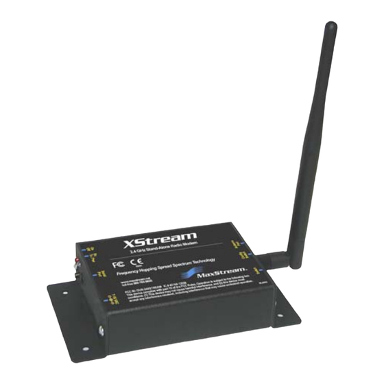
XStream‐PKG‐E™ Ethernet RF Modem – Product Manual v4.2B 1.3. XStream-PKG-E Interface 1.3.1. Front and Back Views 1-01a. Power Switch Move Power Switch to the ON (up) position to power the Figure 1‐01. Front View XStream PKG-E Ethernet RF Modem. 1-01b. I/O & Power LEDs LEDs indicate modem activity as follows:... -
Page 7: System Setup
2.1.1. System Description The PKG-E Ethernet RF Modem can be used as an access point in a network of MaxStream RS- 232/RS-485 RF Modems (or other OEM RF Module Embedded Devices). XStream RF Modems support point-to-point, peer-to-peer, point-to-multipoint and multidrop network topologies. -
Page 8: Com Port Communications
To Install the X-CTU Software: Double-click the “setup_X-CTU.exe” file then follow prompts of the installation screens. This file is located on the MaxStream CD and under the ‘Downloads’ section of the following web page: www.maxstream.net/helpdesk/. Installation #2: Ethernet Com Port Redirector MaxStream provides com port redirection software that creates a com port in the operating system that will forward serial data to the IP address of the Ethernet-connected RF modem. -
Page 9: Setup Com Port And Ip Address
XStream‐PKG‐E™ Ethernet RF Modem – Product Manual v4.2B 2.2.2. Setup Com Port and IP Address The XStream-PKG-E Ethernet RF Modem supports DHCP (Dynamic Host Configuration Protocol) and Auto IP protocols. Both protocols automatically assign IP addresses to nodes of a network. Ethernet RF Modem Discovery The X-CTU Software provides an easy-to-use interface that searches a local network and then displays Ethernet RF Modems found. -
Page 10: Assign Static Ip Address
Select the ‘OK’ button of the “Properties” dialog box. Select the ‘Apply’ button that is under the ‘Changes’ section of the “Ethernet Com Ports” sub- tab. XStream-PKG-E Ethernet RF Modem re-boots and the new IP Address is saved. Figure 2‐05. Properties & Change IP dialog boxes 2.2.4. Change Com Port Number During Com Port Redirector setup, one com port is automatically assigned. -
Page 11: Test Communications (X-Ctu Loopback)
Accessories (Loopback adapter, CAT5 UTP cable, power supplies and RPSMA antennas) Hardware Setup for Loopback Test: Connect the XStream-PKG-E (Ethernet) RF Modem and a PC to active Ethernet ports of the same local network using CAT5 cables (included w/ PKG-EA accessories package). -
Page 12: Telnet Communications
2.3. Telnet Communications In addition to com port communications, Telnet communications are also supported. 2.3.1. Test Communications (Telnet Loopback) MaxStream Wireless links can be tested by connecting to the specific IP address and port number. Test a Wireless Link (Telnet Connection): Follow steps in the “Ethernet RF Modem Discovery”... -
Page 13: Modem Operation
XStream‐PKG‐E™ Ethernet RF Modem – Product Manual v4.2B 3. Modem Operation An on-board RF module enables the XStream-PKG-E RF Modem to send and receive data over- the-air. The RF module operates in five modes. Figure 3‐01. RF Modem Modes of Operation The modem can only be in one mode at a time. 3.1. Idle Mode When not receiving or transmitting data, the module is in Idle Mode. -
Page 14: Transmit Mode
If more data is pending, the transmitting modem assembles a subsequent packet for transmission. 3.2.1. RF Packet The RF packet is the sequence of data used for communicating information between MaxStream Modems. An RF Packet consists of an RF Initializer and RF Data. Figure 3‐03. RF Packet Components ... -
Page 15: Receive Mode
RF data. If serial data is stored in the DI buffer while the modem is in Receive Mode, the serial data will be transmitted after the modem is finished receiving data and returns to Idle Mode. © 2005 MaxStream, Inc. Confidential and Proprietary 15 ... -
Page 16: Sleep Mode
“Wake-up Initializer Timer” (set by LH Command). (Pin Wake-up) Command is issued. For more information about Sleep Modes, refer to the individual commands listed in “Related Commands” column of the table. SM Command is the best starting point for implementing sleep mode configurations. © 2005 MaxStream, Inc. Confidential and Proprietary 16 ... -
Page 17: Command Mode
If no valid AT Commands are received within the time specified by CT (Command Mode Timeout) Command, the Modem automatically returns to Idle Mode. For examples that step through the programming the modem using AT Commands, refer to the Modem Configuration [p19] chapter. © 2005 MaxStream, Inc. Confidential and Proprietary 17 ... -
Page 18: Binary Command Mode
For the XStream Modem to recognize a binary command, the RT (DI2 Configuration) parameter must be set to one. If binary programming is not enabled (RT ≠ 1), the modem will not recognize that the CMD pin is asserted and therefore will not recognize the data as binary commands. © 2005 MaxStream, Inc. Confidential and Proprietary 18 ... -
Page 19: Modem Configuration
PC, use one of the connection options below to send can also be used to commands to the XStream-PKG-E Ethernet RF Modem. program the modem. Option #1 – Local Network Connection Connect a PC and the Ethernet RF Modem to active Ethernet connections of the same local network [as shown in the figure below]. -
Page 20: At Command Mode
Send Bytes [Parameter bytes must be 2 bytes long]: (Send DT (Destination Address) Command) (Least significant byte of parameter bytes) (Most significant byte of parameter bytes) (Send WR (Write) Command) De-assert CMD (Pin is driven low). (Exit Binary Command Mode) © 2005 MaxStream, Inc. Confidential and Proprietary 20 ... -
Page 21: Command Reference
0x1A (26d) Streaming Limit 0 – 0xFFFF (0 = disabled) Networking 0xFFFF 0x14 (20d) Firmware Version 0 x 0xFFFF (Read-only) Diagnostic 0x08 (8d) Write (Special) * Firmware version in which the command and parameter options were first supported. NOTE: Commands issued without a parameter value will return the currently stored parameter. © 2005 MaxStream, Inc. Confidential and Proprietary 21 ... -
Page 22: Command Descriptions
BD register. For example, a rate of 19200 bps can be set by sending the following command line "ATBD4B00". NOTE: When using MaxStream’s X-CTU Software, non-standard interface data rates can only be set and read using the X-CTU ‘Terminal’ tab. Non-standard rates are not accessible through the ‘Modem Configuration’... - Page 23 RS-485 TX enable low By default, DO2 provides RS-232 (Clear-to- high Send) flow control. RS-485 TX enable high Default Parameter Value: 0 Number of bytes returned: 1 Related Commands: RT (DI2 Configuration), TO (DO2 Timeout) Minimum Firmware Version Required: 4.27D © 2005 MaxStream, Inc. Confidential and Proprietary 23 ...
- Page 24 Wake-up Initializer to be sent on the next Binary Command: 0x0D (13 decimal) transmit. WR (Write) Command does not need to be issued with FH Command. Use only with cyclic sleep modes active on remote modems. © 2005 MaxStream, Inc. Confidential and Proprietary 24 ...
- Page 25 Related Commands: DT (Destination Address), network uses a different hopping sequence. ID (Modem VID), MK (Address Mask) Different channels can be used to prevent modems in one network from listening to transmissions of another. © 2005 MaxStream, Inc. Confidential and Proprietary 25 ...
-
Page 26: Parameter Range
ID (Modem VID) Command AT Command: ATID <Networking> Read the modem’s VID. VID is a MaxStream-specific acronym that stands for Binary Command: 0x27 (39 decimal) “Vendor Identification Number”. This number is Parameter Range (user-settable):... -
Page 27: Parameter Range
AT Command Mode. When the DI3 Power-up to pin is de-asserted (low), the modem will Wake-up AT Command Mode into AT Command Mode. This behavior allows Default Parameter Value: 0 modem DTR emulation. Number of bytes returned: 1 Minimum Firmware Version Required: 4.22 © 2005 MaxStream, Inc. Confidential and Proprietary 27 ... - Page 28 Parameter Range: 0 – 0xFFFF [x 200 µs] serial byte is received and if no other byte is Default Parameter Value: 0 received before the RO timeout, the transmission Number of bytes returned: 2 will start. Minimum Firmware Version Required: 4.2AA © 2005 MaxStream, Inc. Confidential and Proprietary 28 ...
-
Page 29: Number Of Bytes Returned: 1
Minimum Firmware Version Required: 4.22 Once the command is issued, the modem will return a value between 0x6 and 0x36 where 0x36 represents a very strong signal level and 0x4 indicates a low signal level. © 2005 MaxStream, Inc. Confidential and Proprietary 29 ... - Page 30 AT Command: ATSH <Diagnostics> Set/Read the serial number low word of the modem. Binary Command: 0x26 (38 decimal) Parameter Range: 0 – 0xFFFF [Read-only] Number of bytes returned: 2 Related Commands: SH (Serial Number High) Minimum Firmware Version Required: 4.27C © 2005 MaxStream, Inc. Confidential and Proprietary 30 ...
- Page 31 When the modem awakens to listen for data, DO2 is asserted and any data received on the DI Pin is transmitted. The PWR pin is also de- asserted (low) when the modem is in Cyclic Sleep Mode. © 2005 MaxStream, Inc. Confidential and Proprietary 31 ...
- Page 32 Figure 4‐03. Correct Configuration (LH > SM) Length of the wake‐up initializer exceeds the time interval of Cyclic Sleep. The receiver is guaranteed to detect the wake‐up initializer and receive the accompanying payload data. Figure 4‐04. Incorrect Configuration (LH < SM) Length of wake‐up initializer is shorter than the time interval of Cyclic Sleep. This configuration is vulnerable to the receiver waking and missing the wake‐up initializer (and therefore also the accompanying payload data). © 2005 MaxStream, Inc. Confidential and Proprietary 32 ...
- Page 33 Related Commands: RR (Retries) not successfully received and have been dropped. Minimum Firmware Version Required: 4.22 The TR Parameter is not non-volatile and will therefore be reset to zero each time the modem is reset. © 2005 MaxStream, Inc. Confidential and Proprietary 33 ...
- Page 34 (Parameter values remain in the modem’s memory until overwritten by future use of WR Command). If changes are made without writing them to non-volatile memory, the modem reverts back to previously saved parameters the next time the modem is powered-on. © 2005 MaxStream, Inc. Confidential and Proprietary 34 ...
-
Page 35: Appendix A: Agency Certifications
IMPORTANT: The 9XStream (900 MHz) and 24XStream (2.4 GHz) RF Modems have been certified by the FCC for use with other products without any further certification (as per FCC section 2.1091). Changes or modifications not expressly approved by MaxStream could void the user’s authority to operate the equipment. -
Page 36: Oem Labeling Requirements
This test is called the Specific Absorption Rate (SAR) testing and measures the emissions from the radio modem and how they affect the person. Over 100 additional antennas have been tested and are approved for use with MaxStream 900 MHz Radio Modems (including “Mag Mount”, “Dome”, “Multi-path” and “Panel” antennas). -
Page 37: Fcc Approved Antennas
Type Gain Application Min. Separation Distance Yagi 6.2 dBi Fixed/Mobile ** 20 cm Yagi 7.2 dBi Fixed/Mobile ** 20 cm MaxStream A09-Y8 Yagi 8.2 dBi Fixed/Mobile ** 20 cm Yagi 9.2 dBi Fixed/Mobile ** 20 cm Yagi 10.2 dBi Fixed/Mobile **... -
Page 38: European Compliance (2.4 Ghz Only)
EMC and safety. Files are located in the ‘documentation’ folder of the MaxStream CD. Important Note MaxStream does not list the entire set of standards that must be met for each country. MaxStream customers assume full responsibility for learning and meeting the required guidelines for each country in their distribution market. -
Page 39: Europe (2.4 Ghz) Approved Antenna List
Channel Spacing: 400 kHz • ITU Classification: 400KF1D • Output Power: 100 mW EIRP • Notified Body Number: 0891 Contact MaxStream (801) 765-9885 if additional information is required. Europe (2.4 GHz) Approved Antenna List Table A‐03. Antennas approved for use with 24XStream (2.4 GHz) RF Modems in Europe Minimum Separation Manufacturer Part Number Type... -
Page 40: Appendix B: Additional Information
XStream‐PKG‐E™ Ethernet RF Modem – Product Manual v4.2B Appendix B: Additional Information 1-Year Warranty XStream RF Modems from MaxStream, Inc. (the ʺProductʺ) are warranted against defects in materials and workmanship under normal use, for a period of 1‐year from the date of purchase. In the event of a product failure due to materials or workmanship, MaxStream will repair or replace the defective product. For warranty service, return the defective product to MaxStream, shipping prepaid, for prompt repair or replacement. The foregoing sets forth the full extent of MaxStreamʹs warranties regarding the Product. Repair or replacement at MaxStreamʹs option is the exclusive remedy. THIS WARRANTY IS GIVEN IN LIEU OF ALL OTHER WARRANTIES, EXPRESS OR IMPLIED, AND MAXSTREAM SPECIFICALLY DISCLAIMS ALL WARRANTIES OF MERCHANTABILITY OR FITNESS FOR A PARTICULAR PURPOSE. IN NO EVENT SHALL MAXSTREAM, ITS SUPPLIERS OR LICENSORS BE LIABLE FOR DAMAGES IN EXCESS OF THE PURCHASE PRICE OF THE PRODUCT, FOR ANY LOSS OF USE, LOSS OF TIME, INCONVENIENCE, COMMERCIAL LOSS, LOST PROFITS OR SAVINGS, OR OTHER INCIDENTAL, SPECIAL OR CONSEQUENTIAL DAMAGES ARISING OUT OF THE USE OR INABILITY TO USE THE PRODUCT, TO THE FULL EXTENT SUCH MAY BE DISCLAIMED BY LAW. SOME STATES DO NOT ALLOW THE EXCLUSION OR LIMITATION OF INCIDENTAL OR CONSEQUENTIAL DAMAGES. THEREFOR, THE FOREGOING EXCLUSIONS MAY NOT APPLY IN ALL CASES. This warranty provides specific legal rights. Other rights which vary from state to state may also apply. Ordering Information Figure B‐01. MaxStream RF Modem Part Numbers Key © 2005 MaxStream, Inc. Confidential and Proprietary 40 ... -
Page 41: Contact Maxstream
XStream‐PKG‐E™ Ethernet RF Modem – Product Manual v4.2B Contact MaxStream Free and unlimited technical support is included with every MaxStream Radio Modem sold. Please use the following resources for additional support: Documentation: http://www.maxstream.net/helpdesk/download.php Technical Support: Phone. (866) 765-9885 toll-free U.S. & Canada (801) 765-9885 Worldwide Live Chat.
Need help?
Do you have a question about the XStream-PKG-E and is the answer not in the manual?
Questions and answers