Table of Contents
Advertisement
Quick Links
www.agelectronica.com
www.agelectronica.com
XBee-PRO PKG-U™ USB RF Modem
XBee-PRO USB RF Modem
RF Modem Operation
RF Modem Configuration
Appendices
Product Manual
For XBee-PRO RF Modem Part Numbers:
®
IEEE
802.15.4 Boxed USB RF Modems by MaxStream
MaxStream
355 South 520 West, Suite 180
Lindon, UT 84042
Phone: (801) 765-9885
Fax: (801) 765-9895
rf-xperts@maxstream.net
www.MaxStream.net (live chat support)
www.agelectronica.com
www.agelectronica.com
v1.xAx
XBP24-PKC-...-U...
www.agelectronica.com
www.agelectronica.com
M100281
2007.01.04
www.agelectronica.com
www.agelectronica.com
Advertisement
Table of Contents

Subscribe to Our Youtube Channel
Related Manuals for MaxStream XBee-PRO PKG-U


Summary of Contents for MaxStream XBee-PRO PKG-U
- Page 1 RF Modem Configuration Appendices Product Manual v1.xAx For XBee-PRO RF Modem Part Numbers: XBP24-PKC-...-U... ® IEEE 802.15.4 Boxed USB RF Modems by MaxStream MaxStream 355 South 520 West, Suite 180 Lindon, UT 84042 Phone: (801) 765-9885 Fax: (801) 765-9895 rf-xperts@maxstream.net M100281 www.MaxStream.net (live chat support)
- Page 2 XBee‐PRO 802.15.4 USB RF Modems v1.xAx [2007.01.04] © 2007 MaxStream, Inc. All rights reserved No part of the contents of this manual may be transmitted or reproduced in any form or by any means without the written permission of MaxStream, Inc. XBee‐PRO PKG‐U™ is a trademark of MaxStream, Inc. Technical Support: Phone: (801) 765‐9885 Live Chat: www.maxstream.net E‐mail: rf‐xperts@maxstream.net © 2007 MaxStream, Inc. ii www.agelectronica.com www.agelectronica.com www.agelectronica.com www.agelectronica.com...
-
Page 3: Table Of Contents
2.4.1. NonBeacon 9 1-Year Warranty 58 2.4.2. NonBeacon (w/ Coordinator) 9 Ordering Information 58 2.4.3. Association 10 Contact MaxStream 59 2.5. Addressing 13 2.5.1. Unicast Mode 13 2.5.2. Broadcast Mode 13 2.6. Modes of Operation 14 2.6.1. Idle Mode 14 2.6.2. -
Page 4: Xbee-Pro Usb Rf Modem
1.1.1. Worldwide Acceptance FCC Approved (USA) Refer to Appendix A [p54] for FCC Requirements. Systems that include XBee-PRO RF Modems inherit MaxStream Certifications. Operates within the ISM (Industrial, Scientific & Medical) 2.4 GHz frequency band Manufactured under ISO 9001:2000 registered standards XBee-PRO RF Modems are optimized for use in US, Canada, Australia, Israel and Europe (contact MaxStream for complete list of approvals). -
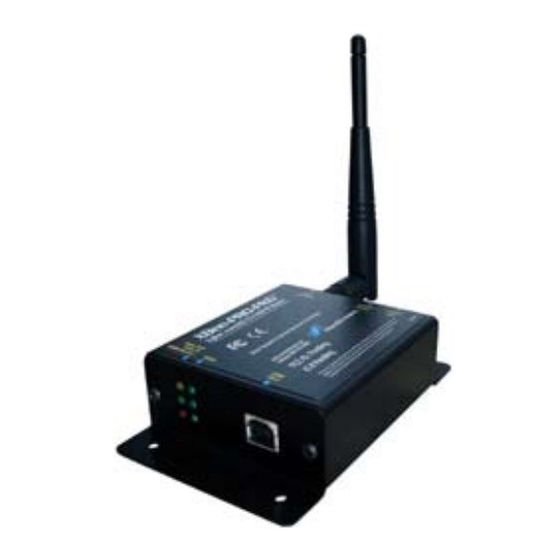
Page 5: Specifications
0 - 70º C (Commercial) Certifications (partial list) United States (FCC Part 15.247) OUR-XBEEPRO Industry Canada (IC) 4214A-XBEEPRO Europe (CE) ETSI (Max. 10 mW transmit power output)* * When operating in Europe: XBee‐PRO RF Modems must be configured to operate at a maximum transmit power output level of 10 dBm. Set the PL parameter to “0” (10 dBm) in order to adhere to European regulations. 1.3. Mechanical Drawings Figure 1‐01. Mechanical drawings of the XBee‐PRO USB RF Modem © 2007 MaxStream, Inc. 5 www.agelectronica.com www.agelectronica.com www.agelectronica.com www.agelectronica.com... -
Page 6: External Interface
Implementation VBUS Power Power the RF modem Transmitted & Received Data Transmit data to and from the RF modem Transmitted & Received Data Transmit data to and from the RF modem Ground Signal Ground © 2007 MaxStream, Inc. 6 www.agelectronica.com www.agelectronica.com www.agelectronica.com www.agelectronica.com... -
Page 7: Rf Modem Operation
Once the USB connection is made and drivers are installed, any software that is able to communicate through a com port can be used to interface with the modem. MaxStream’s proprietary X-CTU Software includes a ‘Terminal’ tab that can be used for configuring the modem and monitoring communications. -
Page 8: Transparent Operation
-> Transmitting data to multiple destinations without entering Command Mode -> Receive success/failure status of each transmitted RF packet -> Identify the source address of each received packet To implement API operations, refer to API sections [p49]. © 2007 MaxStream, Inc. 8 www.agelectronica.com www.agelectronica.com www.agelectronica.com... -
Page 9: Ieee 802.15.4 Networks
Master/Slave relationships. This means that modems remain synchronized without use of master/server configurations and each modem in the network shares both roles of master and slave. MaxStream's peer-to-peer architecture features fast synchronization times and fast cold start times. This default configuration accommodates a wide range of RF data applications. -
Page 10: Association
Active Scan results. Otherwise, the ID (PAN ID) parameter setting will be updated to a PAN ID that was not detected. Not Set (bit 0 = 0) - The Coordinator retains its ID setting. No Active Scan is performed. © 2007 MaxStream, Inc. 10 www.agelectronica.com www.agelectronica.com... - Page 11 BeaconRequest command as before. This process continues until all channels have been scanned, or until 5 PANs have been discovered. When the Active Scan is complete, the results include a list of PAN IDs and Channels that are being used by detected PANs. © 2007 MaxStream, Inc. 11 www.agelectronica.com www.agelectronica.com...
- Page 12 4. End Device Changes once an End Device has associated Changing A1, ID or CH parameters will cause the End Device to disassociate and restart the Association procedure. If the End Device fails to associate, the AI command can give some indication of the failure. © 2007 MaxStream, Inc. 12 www.agelectronica.com www.agelectronica.com www.agelectronica.com...
-
Page 13: Addressing
• DL (Destination Low Address) = 0x0000FFFF • DH (Destination High Address) = 0x00000000 (default value) NOTE: When programming the modem, parameters are entered in hexadecimal notation (without the “0x” prefix). Leading zeros may be omitted. © 2007 MaxStream, Inc. 13 www.agelectronica.com www.agelectronica.com www.agelectronica.com... -
Page 14: Modes Of Operation
Indirect Transmissions can only occur on a Coordinator. Thus, if all nodes in a network are End Devices, only Direct Transmissions will occur. Indirect Transmissions are useful to ensure packet delivery to a sleeping node. The Coordinator currently is able to retain up to 2 indirect messages. © 2007 MaxStream, Inc. 14 www.agelectronica.com www.agelectronica.com... - Page 15 If the transmission is not a broadcast message, the modem will expect to receive an acknowledge- ment from the destination node. If an acknowledgement is not received, the packet will be resent up to 3 more times. If the acknowledgement is not received after all transmissions, an ACK failure is recorded. © 2007 MaxStream, Inc. 15 www.agelectronica.com www.agelectronica.com www.agelectronica.com...
-
Page 16: Sleep Mode
The modem will wake when DTR is asserted and is ready to transmit or receive when the CTS line is low. When waking the modem, the pin must be asserted at least two 'byte times' after CTS goes low. This assures that there is time for the data to enter the DI buffer. © 2007 MaxStream, Inc. 16 www.agelectronica.com www.agelectronica.com... - Page 17 The Coordinator will hold the indirect message for a period 2.5 times the sleeping period indicated by the SP (Cyclic Sleep Period) parameter. The Coordinator's SP parameter should be set to match the value used by the remotes. © 2007 MaxStream, Inc. 17 www.agelectronica.com www.agelectronica.com...
-
Page 18: Command Mode
If no valid AT Commands are received within the time specified by CT (Command Mode Timeout) Command, the RF modem automatically returns to Idle Mode. For an example that illustrates programming the RF modem using AT Commands, refer to the "RF Modem Configuration" chapter [p19]. © 2007 MaxStream, Inc. 18 www.agelectronica.com www.agelectronica.com www.agelectronica.com... -
Page 19: Rf Modem Configuration
USB connection to a PC. Install MaxStream's X-CTU Software to a PC by double-clicking the "setup_X-CTU.exe" file. (The file is located on the MaxStream CD and under the 'Software' section of the following web page: www.maxstream.net/support/downloads.php). Refer to the the ‘X-CTU Software’... -
Page 20: X-Ctu Software
A shortcut for editing PC Setting values is available by clicking on any of the values. Install X-CTU Double-click the "setup_X-CTU.exe" file and follow prompts of the installation screens. This file is located in the 'software' folder of the MaxStream CD and also under the 'Downloads' section of the following web page: www.maxstream.net/support/downloads.php Setup To use the X-CTU software, a module assembly (An RF modem mounted to an interface Board) must be connected to a serial port of a PC. -
Page 21: Command Reference Tables
(802.15.4 - macMinBE). MAC Mode. Set/Read MAC Mode value. MAC Mode enables/disables the use of a 0 - 2 Networking MaxStream header in the 802.15.4 RF packet. When Mode 0 is enabled (MM=0), 0 = MaxStream Mode MM ( v1.x80*) {Addressing} duplicate packet detection is enabled as well as certain AT commands. - Page 22 3 - PollCoordOnPinWake 0 - Pin Wake will not poll the Coordinator for indirect (pending) data 1 - Pin Wake will send Poll Request to Coordinator to extract any pending data bits 4 - 7 are reserved © 2007 MaxStream, Inc. 22 www.agelectronica.com www.agelectronica.com www.agelectronica.com...
- Page 23 Force Disassociation. End Device will immediately disassociate from a Coordinator (if DA ( v1.x80*) {Association} associated) and reattempt to associate. Networking FP ( v1.x80*) Force Poll. Request indirect messages being held by a coordinator. {Association} © 2007 MaxStream, Inc. 23 www.agelectronica.com www.agelectronica.com www.agelectronica.com www.agelectronica.com...
- Page 24 CCA is performed to detect energy on the channel. If the 0 - 0x50 [-dBm] (-44d dBm) detected energy is above the CCA Threshold, the modem will not transmit the packet. * Firmware version in which the command was first introduced (firmware versions are numbered in hexadecimal notation.) © 2007 MaxStream, Inc. 24 www.agelectronica.com www.agelectronica.com www.agelectronica.com...
- Page 25 0 - 4 0 = 8-bit (no parity or 7-bit (any parity) Serial Parity. Set/Read parity settings. 1 = 8-bit even Interfacing 2 = 8-bit odd 3 = 8-bit mark 4 = 8-bit space © 2007 MaxStream, Inc. 25 www.agelectronica.com www.agelectronica.com www.agelectronica.com www.agelectronica.com...
- Page 26 DIO data only. Any samples queued waiting for transmission will be sent first. Sample Rate. Set/Read sample rate. When set, this parameter causes the modem to IR (v1.xA0*) I/O Settings 0 - 0xFFFF [x 1 msec] sample all enabled inputs at a specified interval. © 2007 MaxStream, Inc. 26 www.agelectronica.com www.agelectronica.com www.agelectronica.com www.agelectronica.com...
- Page 27 0 - 6 of -dBm. Actual scan time on each channel is measured as Time = [(2 ^ SD) * 15.36] ms. Total scan time is this time multiplied by the number of channels to be scanned. * Firmware version in which the command was first introduced (firmware versions are numbered in hexadecimal notation.) © 2007 MaxStream, Inc. 27 www.agelectronica.com www.agelectronica.com www.agelectronica.com...
- Page 28 AT Command 0x2B between Guard Times of the AT Command Mode Sequence (GT+CC+GT). The AT 0 - 0xFF Mode Options (‘+’ ASCII) Command Mode Sequence enters the RF modem into AT Command Mode. * Firmware version in which the command was first introduced (firmware versions are numbered in hexadecimal notation.) © 2007 MaxStream, Inc. 28 www.agelectronica.com www.agelectronica.com www.agelectronica.com www.agelectronica.com...
-
Page 29: Command Descriptions
1 - Coordinator will perform Energy Scan to find a free channel, then operate on that channel. 0 - Coordinator will not allow any devices to associate to it. 2 - AllowAssociate 1 - Coordinator will allow devices to associate to it. 3 - 7 [reserved] The binary equivalent of the default value (0x06) is 00000110. ‘Bit 0’ is the last digit of the sequence. © 2007 MaxStream, Inc. 29 www.agelectronica.com www.agelectronica.com www.agelectronica.com www.agelectronica.com... - Page 30 Remote Coordinator did not reply to the Association Request, but an ACK was received 0x10 after sending the request 0x11 [reserved] 0x12 Sync-Loss - Lost synchronization with a Beaconing Coordinator 0x13 Disassociated - No longer associated to Coordinator 0xFF RF Modem is attempting to associate © 2007 MaxStream, Inc. 30 www.agelectronica.com www.agelectronica.com www.agelectronica.com www.agelectronica.com...
- Page 31 (16 for the XBee, 12 for the XBee-PRO). NOTE: Refer the scan table in the SD description to determine scan times. If using API Mode, no <CR>’s are returned in the response. Refer to the API Mode Operation section [p49]. © 2007 MaxStream, Inc. 31 www.agelectronica.com www.agelectronica.com...
- Page 32 19200 bps can be set by sending the following command line "ATBD4B00". NOTE: When using MaxStream’s X-CTU Software, non-standard interface data rates can only be set and read using the X-CTU ‘Terminal’ tab. Non-standard rates are not accessible through the ‘Modem Configuration’...
- Page 33 Default Parameter Value: 0x64 (100 decimal to Idle Mode. (which equals 10 decimal seconds)) Use the CN (Exit Command Mode) command to Number of bytes returned: 2 exit AT Command Mode manually. Related Command: CN (Exit Command Mode) © 2007 MaxStream, Inc. 33 www.agelectronica.com www.agelectronica.com www.agelectronica.com www.agelectronica.com...
- Page 34 Parameter Configuration • RTS flow control Disabled • Analog-to-digital converter RTS Flow Control • Digital input • Digital output DO low DO high Default Parameter Value:0 Parameters 3-5 supported as of firmware version 1.xA0 © 2007 MaxStream, Inc. 34 www.agelectronica.com www.agelectronica.com www.agelectronica.com www.agelectronica.com...
- Page 35 To transmit using a 16-bit address, set the DH parameter to zero and the DL parameter less than 0xFFFF. 0x000000000000FFFF (DL concatenated to DH) is the broadcast address for the PAN. Refer to the XBee/XBee-PRO Addressing section [p19] for more information. © 2007 MaxStream, Inc. 35 www.agelectronica.com www.agelectronica.com...
- Page 36 Minimum Firmware Version Required: v1.x80 the modem expires its transmission retries with- out receiving an ACK on a packet transmission. This count saturates at its maximum value. Set the parameter to “0” to reset count. © 2007 MaxStream, Inc. 36 www.agelectronica.com www.agelectronica.com www.agelectronica.com...
- Page 37 API Operation --> Receive frames use an option bit to indicate that the packet was encrypted. FP (Force Poll) Command <Networking (Association)> The FP command is AT Command: ATFP used to request indirect messages being held by Minimum Firmware Version Required: v1.x80 a Coordinator. © 2007 MaxStream, Inc. 37 www.agelectronica.com www.agelectronica.com www.agelectronica.com www.agelectronica.com...
- Page 38 Unique PAN IDs enable control of which RF packets are received by a modem. Setting the ID parameter to 0xFFFF indicates a global transmission for all PANs. It does not indi- cate a global receive. © 2007 MaxStream, Inc. 38 www.agelectronica.com www.agelectronica.com www.agelectronica.com...
- Page 39 Since the modem uses a 10-bit A/D converter, each sample uses two Bytes. This leads to a maxi- mum buffer size of 46 samples or IT=0x2E. When Sleep Modes are enabled and IR (Sample Rate) is set, the modem will remain awake until IT samples have been collected. © 2007 MaxStream, Inc. 39 www.agelectronica.com www.agelectronica.com www.agelectronica.com...
- Page 40 Default Parameter Value:0 1. Enable PWM1 output (P1 = 2) Related Commands: P1 (PWM1 Enable), AC 2. Apply settings (use CN or AC) (Apply Changes), CN (Exit Command Mode) Minimum Firmware Version Required: v1.xA0 © 2007 MaxStream, Inc. 40 www.agelectronica.com www.agelectronica.com www.agelectronica.com www.agelectronica.com...
- Page 41 MM command disables/enables the use of a Max- Parameter Configuration Stream header contained in the 802.15.4 RF packet. By default (MM = 0), MaxStream Mode is MaxStream Mode enabled and the modem adds an extra header to (802.15.4 + MaxStream header) the data portion of the 802.15.4 packet.
- Page 42 The remotes will adjust this time down by 250 ms to give each node the abil- ity to respond before the base ends the command. Once the ND command has ended, any response received on the base would be discarded. © 2007 MaxStream, Inc. 42 www.agelectronica.com www.agelectronica.com www.agelectronica.com...
- Page 43 XBee-PRO RF Modems optimized for use in Japan contain firmware that limits transmit power out- put to 10 dBm. If PL=4 (default), the maximum power output level is 10 dBm. For a list of modem part numbers approved for use in Japan, contact MaxStream [call 1-801-765-9885 or send e-mail to sales@maxstream.net].
- Page 44 If the channel is not clear, the modem waits for a randomly selected period of time, then checks again to see if the channel is clear. After a time, the process ends and the data is lost. © 2007 MaxStream, Inc. 44 www.agelectronica.com...
- Page 45 This values does not need to be set on all modems for retries to work. If retries are enabled, the transmitting modem will set a bit in the Maxstream RF Packet header which requests the receiving modem to send an ACK (acknowledgement). If the transmitting modem does not receive an ACK within 200 msec, it will re-send the packet within a random period up to 48 msec.
- Page 46 32 bits of the RF modem's unique IEEE Parameter Range: 0 - 0xFFFFFFFF [read-only] 64-bit address. Related Commands: SH (Serial Number High), The modem serial number is set at the factory MY (Source Address) and is read-only. © 2007 MaxStream, Inc. 46 www.agelectronica.com www.agelectronica.com www.agelectronica.com www.agelectronica.com...
- Page 47 Sleep Related Commands: SM (Sleep Mode), ST (Time before Sleep) Mode. ST parameter is only valid with Cyclic Sleep settings (SM = 4 - 5). Coordinator and End Device ST values must be equal. © 2007 MaxStream, Inc. 47 www.agelectronica.com www.agelectronica.com www.agelectronica.com www.agelectronica.com...
- Page 48 If changes are made without writing them to non-volatile memory, the modem reverts back to previously saved parameters the next time the modem is powered-on. NOTE: Once the WR command is sent to the modem, no additional characters should be sent until after the “OK/r” response is received. © 2007 MaxStream, Inc. 48 www.agelectronica.com www.agelectronica.com www.agelectronica.com...
-
Page 49: Api Operation
Escape characters. When sending or receiving a UART data frame, specific data values must be escaped (flagged) so they do not interfere with the UART or UART data frame operation. To escape an interfering data byte, insert 0x7D and follow it with the byte to be escaped XOR’d with 0x20. © 2007 MaxStream, Inc. 49 www.agelectronica.com www.agelectronica.com... -
Page 50: Api Types
0x8A cmdData Status (Byte 5) 0 = Hardware reset 1 = Watchdog timer reset 2 = Associated 3 = Disassociated 4 = Synchronization Lost (Beacon-enabled only) 5 = Coordinator realignment 6 = Coordinator started © 2007 MaxStream, Inc. 50 www.agelectronica.com www.agelectronica.com www.agelectronica.com www.agelectronica.com... - Page 51 ACK (acknowledgement). ASCII characters that value to set the given register. If set to ‘0’, no response is requested. identify the AT Command. If no characters present, register is queried. © 2007 MaxStream, Inc. 51 www.agelectronica.com www.agelectronica.com www.agelectronica.com www.agelectronica.com...
- Page 52 0x04 = Send packet with Broadcast Pan ID Up to 100 Bytes per packet Broadcast = 0xFFFF Setting Frame ID to ‘0' will disable response frame. All other bits must be set to 0. © 2007 MaxStream, Inc. 52 www.agelectronica.com www.agelectronica.com www.agelectronica.com www.agelectronica.com...
- Page 53 1 = Address broadcast Up to 100 Bytes per packet LSB (least significant) last (For example: If RX signal strength = -40 bit 2 = PAN broadcast dBm, “0x28” (40 decimal) is returned) bits 3-7 [reserved] © 2007 MaxStream, Inc. 53 www.agelectronica.com www.agelectronica.com www.agelectronica.com www.agelectronica.com...
-
Page 54: Appendix A: Agency Certifications
IMPORTANT: The XBee-PRO USB RF Modem has been certified by the FCC for use with other products without any further certification (as per FCC section 2.1091). Modifications not expressly approved by MaxStream could void the user's authority to operate the equipment. IMPORTANT: OEMs must test final product to comply with unintentional radiators (FCC section 15.107 &... -
Page 55: Fcc-Approved Antennas (2.4 Ghz)
The preceding statement must be included as a CAUTION statement in OEM product manuals in order to alert users of FCC RF Exposure compliance. © 2007 MaxStream, Inc. 55 www.agelectronica.com www.agelectronica.com... -
Page 56: European Certification
EMC and safety. Files are located in the 'documentation' folder of the MaxStream CD. Important Note MaxStream does not list the entire set of standards that must be met for each country. MaxStream customers assume full responsibility for learning and meeting the required guidelines for each country in their distribution market. -
Page 57: Antenna Usage (Europe)
XBee-PRO (@ 10 dBm Transmit Power, PL parameter value must equal 0) The following antennas have been tested and approved for use with the embedded XBee-PRO RF Module: • Dipole (2.1 dBi, Omni-directional, Articulated RPSMA, MaxStream part number A24-HABSM) • Chip Antenna (-1.5 dBi) • Attached Monopole Whip (1.5 dBi) The RF modem encasement was designed to accommodate the RPSMA antenna option. -
Page 58: Appendix B: Additional Information
1-year from the date of purchase. In the event of a product failure due to materials or workmanship, MaxStream will repair or replace the defective product. For warranty service, return the defective product to MaxStream, shipping prepaid, for prompt repair or replacement. -
Page 59: Contact Maxstream
XBee‐PRO 802.15.4 USB RF Modems v1.xAx [2007.01.04] Appendix B: Additional Information Contact MaxStream Free and unlimited technical support is included with every MaxStream Radio Modem sold. For the best in wireless data solutions and support, please use the following resources: Documentation: www.maxstream.net/support/downloads.php Technical Support: Phone. (866) 765-9885 toll-free U.S.A. & Canada (801) 765-9885 Worldwide Live Chat.
Need help?
Do you have a question about the XBee-PRO PKG-U and is the answer not in the manual?
Questions and answers