Table of Contents
Advertisement
Quick Links
9 XCit e - PKG- U™ USB RF M ode m
9XCit e USB RF Modem
RF Modem Operat ion
RF Modem Configurat ion
Advanced Net working
Appendices
P r o d u ct M a n u a l
For RF Modem Part Num bers: XC09- 009PK...- U...
Low Pow e r , Low Cost Box e d RF M ode m s by M a x St r e a m , I n c.
MaxStream
355 Sout h 520 West , Suit e 180
Lindon, UT 84042
Phone: ( 801) 765- 9885
Fax: ( 801) 765- 9895
rf-xpert s@m axst ream .net
www.MaxSt ream .net ( live chat support )
v 2 . 1
XC09- 038PK...- U...
M100180
2007.01.04
Advertisement
Table of Contents

Related Manuals for MaxStream 9 XCite-PKG-U XC09-009PK-U Series


Summary of Contents for MaxStream 9 XCite-PKG-U XC09-009PK-U Series
- Page 1 XC09- 038PK…- U… Low Pow e r , Low Cost Box e d RF M ode m s by M a x St r e a m , I n c. MaxStream 355 Sout h 520 West , Suit e 180...
- Page 2 9XCite‐PKG‐U™ USB RF Modem ‐ Product Manual v2.1 [2007.01.04] © 2 0 0 7 M a x St r e a m , I n c. All r igh t s r e se r ve d No part of the contents of this manual may be transmitted or reproduced in any form or by any means without the written permission of MaxStream, Inc. XCite™ and XCite‐PKG‐U™ are trademarks of MaxStream, Inc. Technical Support: Phone: (801) 765‐9885 Live Chat: www.maxstream.net E‐mail: rf‐xperts@maxstream.net ii © 2007 MaxStream, Inc.
-
Page 3: Table Of Contents
4 .1 . Addr e ssin g 2 8 4.1.1. Vendor I dent ificat ion Num ber ( ATI D) 28 4.1.2. Channel ( ATHP) 29 4.1.3. Dest inat ion Address ( ATDT) and Address Mask ( ATMK) 29 iii © 2007 MaxStream, Inc. -
Page 4: Xcit E Usb Rf M Ode M
I SM ( I n du st r ia l, Scie n t ific & M e dica l) license- free 902- 928 MHz frequency band Manufact ured under I SO 9 0 0 1 :2 0 0 0 r e gist e r e d st a n da r ds © 2007 MaxStream, Inc. -
Page 5: Spe Cifica T Ion S
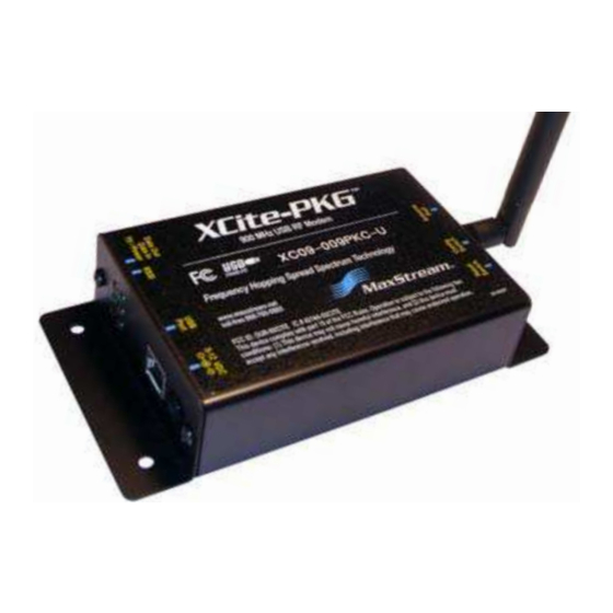
Half-wave dipole whip, 6.75” (17.15cm), 2.1 dBi gain Impedance 50 ohms unbalanced Certifications (partial list) FCC Part 15.247 OUR-9XCITE Industry Canada (IC) 4214A-9XCITE 1 .3 . M e ch a n ica l D r a w in gs Figure 1‐01. XCite‐PKG‐U (USB) RF Modem © 2007 MaxStream, Inc. -
Page 6: Ex T E R N A L I N T E R Fa Ce
1 - 0 3 c. An t e n n a Por t This port is a 50 Ohm RF signal connect or for connect ing t o an RPSMA ( Reverse Polarit y SMA) t ype ant enna. © 2007 MaxStream, Inc. -
Page 7: Pin Sign A Ls
RF m odem is connect ed t o USB. Do not disconnect t he ext ernal power source wit hout first disconnect ing t he XCit e- PKG- U RF Modem from t he USB connect or. © 2007 MaxStream, Inc. -
Page 8: Rf Modem Operation
( such as a PDA wit h USB on- t he- go support ) m ay connect t o and ut ilize a MaxSt ream USB RF Modem . Cont act MaxSt ream for inform at ion about device drivers. 8 © 2007 MaxStream, Inc. -
Page 9: Syst E M D E Scr Ipt Ion
XCit e- PKG RF Modem s and m ay be int egrat ed int o OEM- designed product s t o t ransm it and receive dat a over- t he- air. Figure 2‐01. The XCite USB RF Modem in a Point‐to‐Multipoint Data Radio System * The ʺOEM RF Module Embedded Deviceʺ represents any device that contains in it a MaxStream OEM RF Mod‐ ule. NOTE: XCite and XStream Radio Modems can seamlessly communicate data between each other. The PKG-R units shown can therefore be from either product family. -
Page 10: M Ode S Of Ope R A T Ion 1
) and is t ransm it t ed. The m odem cont inues t o t ransm it dat a packet s unt il t he DI buffer is em pt y. Once t ransm ission is finished, t he m odem ret urns t o I dle Mode. This progression is shown below: Figure 2‐03. Transmission of data 10 © 2007 MaxStream, Inc. -
Page 11: Receive Mode
I f serial dat a- t o- t ransm it is st ored in t he DI buffer while t he m odem is giving precedence t o Receive Mode, t he dat a will be t ransm it t ed aft er t he m odem finishes receiving dat a and ret urns t o I dle Mode. 11 © 2007 MaxStream, Inc. -
Page 12: Sleep Modes
DI Pin is t ransm it t ed. The PWR pin is also de- assert ed ( low) when t he m odem is in Cyclic Sleep Mode. These pins are assert ed each t im e t he m odem cycles 12 © 2007 MaxStream, Inc. - Page 13 The cyclic interval time defined by the SM (Sleep Mode) command must be shorter than the interval time defined by LH (Wake-up Initializer Timer) command. Figure 2‐05. Correct Configuration (LH > SM): The length of the wake‐up initializer exceeds the time interval of Cyclic Sleep. The receiver is guaranteed to detect the wake‐up initializer and receive the accompanying payload data. 13 © 2007 MaxStream, Inc.
-
Page 14: Com M And Mode
[ OR] Send ATCN ( Exit Com m and Mode) Com m and. For an example of programming the RF modem using AT Commands and descriptions of each config- urable parameter, refer to the "RF Modem Configuration" chapter. 14 © 2007 MaxStream, Inc. -
Page 15: Rf M Ode M Con Figu R A T Ion 1
These param et ers enable feat ures t hat need t o be set before t he m odule is used in t he field. Non-AT Set t able Param et ers can only be m odified using t he following m eans: • X- CTU Soft ware " Modem Configurat ion" t ab 15 © 2007 MaxStream, Inc. -
Page 16: Con Figur A T Ion Soft W A R
" 0x1F" . To save t he new value t o t he m odem ’s non- volat ile m em ory, issue WR ( Writ e) com m and aft er m odifying param et ers. 16 © 2007 MaxStream, Inc. -
Page 17: Com M A N D Re Fe R E N Ce Ta Ble
[Read-only] Firmware Version. Read firmware version currently loaded on 0 – 0xFFFF Diagnostic radio modem. [Read-only] Write. Write parameters to radio modem’s non-volatile memory in order for changes to persist through next power-up (Special) or reset. 17 © 2007 MaxStream, Inc. - Page 18 Time before Sleep. Set time period of inactivity (no serial or RF data is sent or received) before activating Sleep Mode. 0x10 – 0xFFFF Sleep 0x64 Use with Cyclic Sleep and Serial Port Sleep [refer to SM [x 100 ms] (Low Power) (100d) Command] 18 © 2007 MaxStream, Inc.
-
Page 19: Com M A N D D E Scr Ipt Ion
Set t ing 7 bit s and Mark or Space parit y ( NB Param et er) will result in a set t ing of 7 bit s and no 8 bits parit y. Default Parameter Value: 1 Number of bytes returned: 1 19 © 2007 MaxStream, Inc. - Page 20 < AT Com m and: AT Com m and Mode Opt ions> CN Com m and allows users t o explicit ly exit AT Com - m and Mode and ret urn t he radio m odem int o I dle Mode. AT Com m a n d: CN 20 © 2007 MaxStream, Inc.
- Page 21 D e fa u lt Pa r a m e t e r Va lu e : 0 Re la t e d Com m a n ds: I D ( Modem I D) , HP ( Channel) , MK ( Address Mask) 21 © 2007 MaxStream, Inc.
-
Page 22: Addressing
Default Parameter Value: 0 channels used on different radio m odem s can be Number of bytes returned: 1 separat ed m ore t hey should be. This will provide for m ore isolat ion and less int erference. 22 © 2007 MaxStream, Inc. - Page 23 Pa r a m e t e r Ra n ge : 0 - 0x7FFF ( above t his range is Read- only) # of byt e s r e t ur n e d: 2 D e fa u lt Pa r a m e t e r Va lu e : 0x3332 23 © 2007 MaxStream, Inc.
- Page 24 The lengt h of t he wake- up init ializer is short er t han t he t im e int erval of Cyclic Sleep. This configu- rat ion is vulnerable t o t he receiver waking and m issing t he wake- up init ializer ( and t herefore also t he accom panying payload dat a) . 24 © 2007 MaxStream, Inc.
- Page 25 Unless t he WR ( Writ e) Com m and is issued aft er t he RE Com m and, t he default set t ings will not be saved in t he event of radio m odem reset or pow er- down. AT Com m a n d: RE Re la t e d Com m a n d: WR ( Writ e) 25 © 2007 MaxStream, Inc.
- Page 26 Pa r a m e t e r Ra n ge : 0 - 0xFFFF [ Read- only] # of byt e s r e t ur n e d: 2 Re la t e d Com m a n d: SH ( Serial Num ber High) 26 © 2007 MaxStream, Inc.
- Page 27 's m em ory unt il explicit ly overwrit t en by fut ure uses of WR Com m and.) AT Com m a n d: WR 27 © 2007 MaxStream, Inc.
-
Page 28: Advanced Networking
VI D addressing ensures t hat radio m odem s ignore t ransm issions and recept ions of XCit e Radio Modem s having a different VI D in t he sam e vicinit y. To request a unique VI D, cont act MaxSt ream t o obt ain t he VI D Request Form . 28 © 2007 MaxStream, Inc. ... -
Page 29: Dest Inat Ion Address ( Atdt) And Address Mask ( Atmk)
The Pseudo Code uses t he bit- wise " AND" operat ion, " &" . This operat ion is perform ed bit by bit on each of t he 16 bit s in t he TXDT, RXDT and RXMK param et ers. 29 © 2007 MaxStream, Inc. ... - Page 30 Dest inat ion Address of t he Receiver, or if it m at ches t he Receiver Address Mask, t he packet is accept ed. Ot herwise, t he packet is discarded. Note:When performing this comparison, any "0" values in the Receiver Address Mask are treated as irrelevant and are ignored. 30 © 2007 MaxStream, Inc. ...
-
Page 31: Appe N Dix A: Age N Cy Ce R T Ifica T Ions 3
I ncrease t he separat ion bet ween t he equipm ent and receiver, Connect equipm ent and receiver t o out let s on different circuit s, or Consult t he dealer or an experienced radio/ TV t echnician for help. 31 © 2007 MaxStream, Inc., Confidential & Proprietary ‐ All Rights Reserved ... -
Page 32: Lim It Ed Modular Approval
NOTE: The separat ion dist ance indicat ed in t he above is 30 cm , but any dist ance great er t han or equal t o 23 cm can be used ( per MPE evaluat ion) . 32 © 2007 MaxStream, Inc., Confidential & Proprietary ‐ All Rights Reserved ... -
Page 33: I C ( I N Du St R Y Ca N A Da ) Ce R T Ifica T Ion 3
Fixed/Mobile ** 1/4 wave integrated wire antenna 1.9 dBi * FCC‐approved antennas not inventoried by MaxStream ‐ Contact MaxStream for more information. ** Can be approved for portable applications if integrator gains approval through SAR testing Over 100 addit ional ant ennas t hat have been t est ed and are approved for use wit h MaxSt ream 900 MHz Radio Modem s ( including " Mag Mount " , " Dom e" , " Mult i- pat h" and " Panel" ant ennas) . -
Page 34: Appendix B: Additional Information
ALL WARRANTI ES OF MERCHANTABI LI TY OR FI TNESS FOR A PARTI CULAR PURPOSE. I N NO EVENT SHALL MAXSTREAM, I TS SUPPLI ERS OR LI CENSORS BE LI ABLE FOR DAMAGES I N EXCESS OF THE PURCHASE PRI CE OF THE PRODUCT, FOR ANY LOSS OF USE, LOSS OF TI ME, I NCONVENI ENCE,... -
Page 35: Con T A Ct M A X St R E A
( 801) 765- 9885 Worldwide Live Chat . www.m axst ream .net E- Mail. rf-xpert s@m axst ream .net MaxSt ream office hours are 8: 00 am - 5: 00 pm [ U.S. Mount ain St andard Tim e] 35 © 2007 MaxStream, Inc.
Need help?
Do you have a question about the 9 XCite-PKG-U XC09-009PK-U Series and is the answer not in the manual?
Questions and answers