
Subscribe to Our Youtube Channel
Related Manuals for Allied Telesis AT-9108


Summary of Contents for Allied Telesis AT-9108
- Page 1 Gigabit ® Switches AT-9108 AT-8518 AT-8525 AT-8550 Installation Guide Version 4.x...
-
Page 3: Installation Guide
AT-9108 AT-8518 AT-8525 AT-8550 Gigabit Switches Installation Guide PN 613-10841-00 Rev A... - Page 4 Copyright 1999 Allied Telesyn International, Corp. 960 Stewart Drive Suite B, Sunnyvale CA 94086 USA All rights reserved. No part of this publication may be reproduced without prior written permission from Allied Telesyn International, Corp. CentreCOM is a registered trademark of Allied Telesyn International, Corp. Ethernet is a registered trademark of Xerox Corporation.
-
Page 5: Table Of Contents
Table of Contents Preface ....................................v Introduction .................................... v Terminology ................................... v Document Conventions .................................vi Related Publications ................................vi Chapter 1 Overview ................................... 1-1 About the Switches................................1-1 Summary of Features ................................. 1-2 Port Connections .......................... - Page 6 AT-9108, AT-8518, AT-8525 and AT-8550 Technical Specifications ................. B-1 Appendix C Technical Support Fax Order............................C-1 Incident Summary................................C-1 Appendix D AT-9108, AT-8518, AT-8525, and AT-8550 Installation Guide Feedback ..............D-1 Appendix E Where to Find Us ................................E-1...
-
Page 7: Preface
This preface provides an overview of this guide, describes guide conventions, and lists other publications that may be useful. Introduction This guide provides the required information to install and configure the AT-9108 (SX and LX), AT-8518 (SX and LX), AT-8525 (SX and LX) and AT-8550 (SX and LX) Gigabit Ethernet Switches. -
Page 8: Document Conventions
Visit our website at: www.alliedtelesyn.com/techhome.htm and download the following guides: AT-9108, AT-8518, AT-8525, AT-8550 User’s Guide , PN 613-10793-00 AT-9108, AT-8518, AT-8525, AT-8550 User’s Command Guide , PN 613-10794-00 The following guides are shipped with the product: AT-9108, AT-8518, AT-8525 and AT-8550 Installation Guide,... -
Page 9: Chapter 1 Overview
Chapter 1 Overview This chapter describes the following: " Features of the AT-9108, AT-8518, AT-8525 and AT-8550 Gigabit Ethernet switches " How to use the switches in your network configuration " Front and rear views of the switches " Factory default settings... -
Page 10: Summary Of Features
Summary of Features By addressing the entire spectrum of Ethernet data rates (10/100/1000 Mbps), the switches enable you to introduce high-speed Gigabit Ethernet backbones into your existing network, while maintaining established connections to the 10 Mbps and 100 Mbps segments that already exist. Summary of Features The switches have the following features: "... -
Page 11: Port Connections
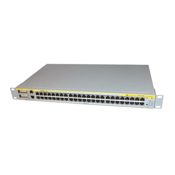
1000Base-LX GBIC transceivers already installed. GBIC modules can also be ordered separately. Contact your Allied Telesyn dealer for the availability of the GBIC modules. Figure 1-1 shows the front view of the AT-9108 (common to both SX and LX configurations). GIGABIT ETHERNET SWITCH... - Page 12 Summary of Features The AT-8525 provides 24 auto-negotiating 10Base-T/100Base-TX ports, one Gigabit Ethernet port, and one redundant Gigabit Ethernet port. The AT-8525SX model has the 1000Base-SX GBIC transceiver already installed, and the AT-8525LX model has the 1000Base-LX GBIC transceiver already installed. You can also order GBIC modules separately.
-
Page 13: Leds
100 m (328 ft) Note For more information on 1000Base-SX and 1000Base-LX link characteristics, refer to IEEE 802.3z, Section 38. LEDs Table 1-2 describes the light emitting diode (LED) indications on the AT-9108.. Table 1-2 AT-9108 LED Color Indicates Power Green The switch is powered up. - Page 14 Summary of Features Table 1-3 describes the LED indications on the AT-8518. Table 1-3 AT-8518 LED Color Indicates Power Green The switch is powered up. Yellow The switch is indicating a power, overheat, or fan failure. DIAG Green flashing: Slow Power On Self Test (POST) in progress.
-
Page 15: Full-Duplex
AT-9108, AT-8518, AT-8525, and AT-8550 Installation Guide Table 1-4 describes the LED indications on the AT-8525 and the AT-8550. Table 1-4 AT-8525 and AT-8550 LEDs Color Indicates Power Green The switch is powered up. Yellow The switch is indicating a power, overheat, or fan failure. -
Page 16: Port Redundancy
Summary of Features Port Redundancy The AT-8518, AT-8525, and AT-8550 switches have optional redundant Gigabit Ethernet ports. Using the redundant port, you can dual-home the switch to one or two switches. Figure 1-5 illustrates a switch dual-homed to two different switches. 10/100BASE-T ETHERNET SWITCH WITH GIGABIT ETHERNET 1000BASE-X... -
Page 17: Network Configuration Examples
AT-9108, AT-8518, AT-8525, and AT-8550 Installation Guide Network Configuration Examples This section describes where to position the switches within your network. One common use of the switches is on a Gigabit Ethernet backbone. Figure 1-6 shows an example of a Gigabit Ethernet backbone within a building. - Page 18 Network Configuration Examples Another common use for the switches is in a campus environment, as shown in Figure 1-7. AT-8525 ETHERNET SWITCH 10/100BASE-T WITH GIGABIT ETHERNET MDI-X 10/100BASE-TX 1000BASE-X ACTIVITY POWER LINK ON DISABLED MGMT. Gigabit Switch Gigabit Switch ETHERNET SWITCH 10/100BASE-T ETHERNET WITH GIGABIT...
-
Page 19: Switch Rear View
AT-9108, AT-8518, AT-8525, and AT-8550 Installation Guide Switch Rear View Figure 1-8 shows the rear view common to the switches. Power socket and fuse RPS port Console port MODEL/NUMBER MADE IN USA PART NUMBER SERIAL NUMBER MAC ADDRESS 130001-00 Rev.03... -
Page 20: Factory Defaults
Factory Defaults Factory Defaults Table 1-5 shows factory defaults for the all switch models. Table 1-5 Switch Factory Defaults Item Default Setting Port status Enabled on all ports Serial or Telnet user admin with no password and user with no password account Console port configuration 9600 baud, eight data bits, one stop bit, no parity, XON/XOFF... -
Page 21: Installation And Setup
Appendix A of this guide. Verifying the Switch Package Check your package for the following contents: " One gigabit Ethernet switch (AT-9108, AT-8518, AT-8525 or AT-8550) " Two rackmount brackets and eight flathead screws " Four self-adhesive rubber feet " One power cord "... -
Page 22: Determining The Switch Location
Determining the Switch Location Determining the Switch Location The switches are suited for use in the office, where it can be free-standing, or mounted in a standard 19-inch equipment rack. Alternatively, the device can be rack- mounted in a wiring closet or equipment room. Two mounting brackets are supplied with the switch. -
Page 23: Free-Standing
AT-9108, AT-8518, AT-8525, and AT-8550 Installation Guide Insert four flathead screws and fully tighten with a suitable screwdriver, as shown in Figure 2-1. fit_rack.eps Figure 2-1 Fitting the Mounting Bracket Repeat the three previous steps for the other side of the switch. -
Page 24: Connecting Equipment To The Console Port
Connecting Equipment to the Console Port Connecting Equipment to the Console Port Connection to the console port is used for direct local management. The switch console port settings are set as follows: " Baud rate — 9600 " Data bits — 8 "... -
Page 25: Powering Up The Switch
After turning on power to the switch, it performs a Power On Self-Test (POST). During the POST, all ports are temporarily disabled, the packet LED is off, the Power LED is on, and the DIAG LED (AT-9108, AT-8518) or MGMT LED (AT-8525, AT-8550) flashes. -
Page 26: Logging In For The First Time
Administrator capabilities allow you to access all switch functions. Note For more information on switch security, refer to the AT-9108, AT-8518, AT-8525, and AT-8550 User’s Guide. See “Related Publications” on page vi. At the password prompt, press [Return]. The default name, admin, has no password assigned. When you have successfully logged on to the switch, the command-line prompt displays the name of the switch in its prompt. -
Page 27: Where To Go Next
You are now ready to manage your switch. Go to Allied Telesyn’s website at www.alliedtelesyn.com/techhome.htm and download the following manuals for information on how to configure and manage your switch: " AT-9108, AT-8518, AT-8525, and AT-8550 User’s Guide " AT-9108, AT-8518, AT-8525, and AT-8550 Command Reference... -
Page 29: Chapter 3 Troubleshooting
Chapter 3 Troubleshooting If you encounter problems when using the switch, this chapter may be helpful. If you have a problem not listed here or in the AT-9108, AT-8518, AT-8525, and AT-8550 User’s Guide, contact your local technical support representative. LEDs Power LED does not light: Check that the power cable is firmly connected to the device and to the supply outlet. -
Page 31: Appendix A Safety Information
Appendix A Safety Information Important Safety Information Note Please read the following safety information thoroughly before installing the switches. " Installation and removal of the unit must be carried out by qualified personnel only. " To reduce the risk of fire or electrical shock, install the unit in a temperature- and humidity-controlled indoor area free of conductive contaminants. -
Page 32: Power Cord
Important Safety Information " This must be approved for the country where it is used: Power Cord " The cord set must be UL-approved and CSA- USA and Canada certified. " The minimum specification for the flexible cord is No. 18 AWG, Type SV or SJ, 3-conductor. -
Page 33: Lithium Battery
AT-9108, AT-8518, AT-8525, and AT-8550 Installation Guide " The battery in the bq4830 device is encapsulated and not user-replaceable. Lithium Battery Warning There is a danger of explosion if the battery is incorrectly replaced. " Dispose of used batteries according to the manufacturer’s instructions. -
Page 35: At-9108, At-8518, At-8525 And At-8550 Technical Specifications
Appendix B AT-9108, AT-8518, AT-8525 and AT-8550 Technical Specifications Height: 3.5 inches x Width: 17.32 inches x Depth: 17.32 inches Physical Dimensions Weight: 10 kg Environmental Requirements Operating Temperature 0 to 40° C Storage Temperature -10 to 70 ° C... - Page 36 Power Supply AC Line Frequency 47Hz to 63Hz Input Voltage Options 90VAC to 264VAC, auto-ranging Current Rating 100-120/200-240 VAC 3.0/1.5 A Refer to the AT-9108, AT-8518, AT-8525, and AT-8550 User’s Guide, Appendix A, Standards Supported for a list of supported standards.
-
Page 37: Technical Support Fax Order
Appendix C Technical Support Fax Order Name __________________________________________________________________ Company _______________________________________________________________ Address ________________________________________________________________ City ___________________ State/Province ____________________________________ Zip/Postal Code _____________ Country____________________________________ Phone __________________________ Fax____________________________________ Incident Summary Model number of Allied Telesyn product I am using ____________________________ Network software products I am using_______________________________________ ________________________________________________________________ Brief summary of problem_________________________________________________ ________________________________________________________________... -
Page 39: At-9108, At-8518, At-8525 And At-8550 Installation Guide Feedback
Appendix D AT-9108, AT-8518, AT-8525 and AT-8550 Installation Guide Feedback Please tell us what additional information you would like to see discussed in the guide. If there are topics you would like information on that were not covered in the guide, please photocopy this page, answer the questions and fax or mail this form back to Allied Telesyn. -
Page 41: Appendix E Where To Find Us
Appendix E Where to Find Us For Technical Support or Service Location Phone Americas 1 (800) 428-4835 1 (503) 639-3946 United States, Canada, Mexico, Central America, South America Asia (+65) 3815-612 (+65) 3833-830 Singapore, Taiwan, Thailand, Malaysia, Indonesia, Korea, Philippines, China, India, Hong Kong Australia 1 (800) 000-880 (+61) 2-9438-4966... - Page 43 Allied Telesyn International, Corp. 960 Stewart Drive, Suite B Sunnyvale, California 94086 USA US & Canada 800.424.4284 408.736.0100 International 408.730.0950 408.736.0286 Web Address http://www.alliedtelesyn.com...
Need help?
Do you have a question about the AT-9108 and is the answer not in the manual?
Questions and answers