Allied Telesis AT-8900 Hardware Reference Manual
Hide thumbs
Also See for AT-8900:
- Quick install manual (13 pages) ,
- Troubleshooting (5 pages) ,
- Release note (232 pages)

Related Manuals for Allied Telesis AT-8900


Summary of Contents for Allied Telesis AT-8900
- Page 1 AT-8900, AT-9900, AT-9900s Switches Hardware Reference AT-8948 AT-9924T AT-9924SP AT-9924T/4SP AT-9924Ts...
- Page 2 Hardware Reference for AT-8900, AT-9900 and AT-9900s Series Switches Document Number C613-03092-00 REV C © 2003-2005 Allied Telesyn Inc. All rights reserved. No part of this publication may be reproduced without prior written permission from Allied Telesyn Inc. Allied Telesyn Inc. reserves the right to change specifications and other information in this document without prior written notice.
-
Page 3: Table Of Contents
Using Online Documentation ................12 Using AT-TFTP Server ..................13 Using Windows Terminal and HyperTerminal ........... 14 How the Switch Starts Up ................17 AT-8900 and AT-9900 Switches ..............17 Process flow ..................17 Overrides ................... 17 Regular output .................. 18 Types of messages ................ - Page 4 AT-8900, AT-9900, AT-9900s Series Switches Management Ports ..................28 RS-232 Terminal Port (ASYN0) ..............28 Out-of-Band Ethernet Management Port ..........28 Cables ......................29 RS-232 Terminal and Modem Cables ............29 RJ-45 to DB9 female terminal cable ............ 29 RJ-45 to DB9 male modem cable ............30 Cables for RJ-45 Ethernet LAN Interfaces ..........
-
Page 5: Models Covered By This Document
AT-FAN01 (fan-only module) ■ Why You Should Read This Document Use this document to familiarise yourself with the AT-8900, AT-9900, and AT-9900s Series switches and hardware features, including power supply units (PSUs). This reference can also help you with installation and maintenance. -
Page 6: Hardware Overview
• AT-9924SP model AT-9900s Series Switch ■ • AT-9924Ts model The AT-8900, AT-9900, and AT-9900s Series switches have the following common traits: Dimensions Height: 44.5 mm, plus 5.1mm if the rubber feet are used ■ Width: 440mm, excluding rack-mounting brackets ■... -
Page 7: At-8900 Series Switch
Hardware Reference AT-8900 Series Switch The AT-8948 switch is the sole model in the AT-8900 Series and meets the exceptionally high performance demands of high-end applications. It delivers wire-speed switching performance in a robust 1U rack mount platform. Environmental Operating temperature range: 0ºC to 50º C (32 to 122ºF) ■... -
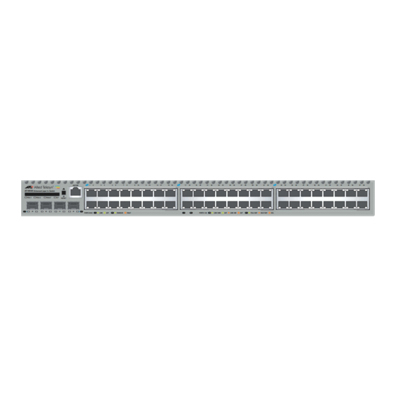
Page 8: At-8948 Model
AT-8900, AT-9900, AT-9900s Series Switches AT-8948 model Key features are: Autonegotiating multi-layer gigabit switch ■ 48 10BASE-T/100Base-TX ports (RJ-45 connectors), auto MDI/MDI-X, full ■ or half duplex 4-port 1000BASE-X SFP uplink sockets, full duplex ■ Hot-swappable, load sharing PSUs ■... -
Page 9: At-9900 Series Switch
Hardware Reference AT-9900 Series Switch AT-9900 Series switches are advanced gigabit Ethernet multi-layer switches, perfect for the high-density rack environment where space is at a premium. Environmental Operating temperature range: 0ºC to 50ºC (32ºF to 104ºF) ■ conditions Storage temperature range: -25ºC to 70ºC (-13ºF to 158ºF) ■... -
Page 10: At-9924T/4Sp Model
AT-8900, AT-9900, AT-9900s Series Switches AT-9924T/4SP model Key features are: Autonegotiating, multi-layer gigabit switch ■ 24 10BASE-T/100BASE-TX/1000BASE-T ports (RJ-45 connectors) ■ 4 Small Form Factor Pluggable (SFP) ports ■ Hot-swappable, load sharing PSUs ■ Optional AT-ACC01 network processor accelerator card ■... -
Page 11: At-9900S Series Switch
Hardware Reference AT-9900s Series Switch The AT-9900s Series switch is a gigabit link aggregation switch that operates with other switches that have 10 Mb/100Mb/1Gb/10Gb Ethernet ports. This switch can act as a gigabit server backbone or pass aggregated traffic over its gigabit ports. -
Page 12: Switch Leds
AT-8900, AT-9900, AT-9900s Series Switches Switch LEDs The following LEDs report operations and faults and on the AT-8900, AT-9900, and AT-9900s switches: ■ SFP port LEDs RJ-45 port LEDs ■ Ethernet port LEDs ■ System LEDs ■ SFP port LEDs... -
Page 13: Ethernet Port Leds
Hardware Reference Ethernet port LEDs State Description Green An XFP transceiver is installed and a 10 Gb link (Link Activity) has been established. Green flashing An XFP transceiver is installed and link activity is occurring. Amber A 10/100 Mbps link has been established. Amber flashing 10/100 Mbps activity is occurring. -
Page 14: Using Online Documentation
AT-8900, AT-9900, AT-9900s Series Switches Description (cont) State Fault The switch or management software is malfunctioning. This LED lights and then turns off after hardware initialises. 1 Flash One or more heatsink fans has failed or is operating below the recommended speed. -
Page 15: Using At-Tftp Server
Hardware Reference Using AT-TFTP Server This section explains how to access and use the AT-TFTP Server. You can transfer configuration files as well as download software upgrades with AT-TFTP Server. If AT-TFTP Server has not been installed, install it from the Documentation and Tools CD-ROM. -
Page 16: Using Windows Terminal And Hyperterminal
AT-8900, AT-9900, AT-9900s Series Switches Using Windows Terminal and HyperTerminal You can use a PC running terminal emulation software as the manager console, instead of a terminal. There are many terminal emulation applications available for PCs, but the most readily available are the Terminal and HyperTerminal applications included in Microsoft Windows 98, 2000, and XP Professional. - Page 17 Hardware Reference In the “Connect using” field on the Connect To dialog box, select the COM port on the PC used to connect to the switch. and click the OK button. In the COMn Properties dialog box, set port parameters as follows, and click the OK button.
- Page 18 AT-8900, AT-9900, AT-9900s Series Switches From the main HyperTerminal window, select Properties from the File menu. Click the Settings tab, and set the Properties dialog box as follows. Click ASCII Setup to display the ASCII Setup dialog box, and ensure the following options are not selected: •...
-
Page 19: How The Switch Starts Up
Installation and Safety Guide for basic login instructions or to the Getting Started chapter in the Software Reference. AT-8900 and AT-9900 Switches Process flow When an AT-8900 or AT-9900 switch starts, it performs the following operations. Stage This happens... Done by... -
Page 20: Regular Output
AT-8900, AT-9900, AT-9900s Series Switches Regular output The following messages are an example of output from AT-8900 and AT-9900 switches. INFO: Self tests beginning. INFO: RAM test beginning. PASS: RAM test, 131072k bytes found. INFO: BBR tests beginning. PASS: BBR test, 512k bytes found. - Page 21 Hardware Reference Message Description (cont) FAIL: BBR test. Error address = BBR size/location test failed at the given location. The test location at this location failed, indicating the end of memory, but a valid location was discovered in the 255 long words following this location.
-
Page 22: At-9900S Switches
AT-8900, AT-9900, AT-9900s Series Switches AT-9900s Switches This section explains how AT-9900s switches start initially, including error messages. The following types of software play key roles during startup. Software Description Base Product software that is typically the “preferred” base package installed. -
Page 23: Regular Output
Hardware Reference Regular output Bootloader and product software (AlliedWare) display a series of messages similar to those in the following figure during routine startup for the AT-9900s switch. ------------------------------------------------------------ Bootloader v1-00, built Feb 10 2005 ------------------------------------------------------------ Initial RAM test ....... passed Available RAM ........ -
Page 24: Bootloader Messages
AT-8900, AT-9900, AT-9900s Series Switches Bootloader The following table explains messages that bootloader software displays at messages initial startup for the AT-9900s switch. Message Description Bootloader <version>, built Banner that identifies the bootloader software. <date> Initial RAM test...passed Whether initial RAM tests are successful. If tests detect a problem with DRAM, the switch cannot be used. -
Page 25: Alliedware Messages
Hardware Reference Message Description (cont) ERROR: Fallback area is The switch is shifting to bootloader software because the corrupt - launching the fallback area in flash is unformatted or corrupt. It displays a bootloader CLI bootloader prompt. Contact your authorised distributor or reseller before proceeding. - Page 26 AT-8900, AT-9900, AT-9900s Series Switches Message Description (cont) Installing product_apps.img Whether the product application image of the given size is (8925892 bytes)...done installed in RAM and able to execute. This file is part of the installed package. Installing product_apps.img Failure could mean not enough RAM or the package is (8925892 bytes)...failed...
- Page 27 Hardware Reference Message Description (cont) ERROR: Failed to extract The product application image could not be extracted from product_apps.img from the package file because the package file is corrupt or there package to RAM is not enough RAM. Manually restart the switch with fallback software (for details, see “Overrides”...
-
Page 28: Sfp Ports
SFP transceivers are compact, hot-swappable, and high speed. Certain fibre and copper SFP transceivers are supported so that you can interchange port types to meet changing network requirements. AT-8900 and AT-9900 switches have 1000BASE-X Small Form Factor Pluggable (SFP) uplink sockets conveniently located on the front panels. -
Page 29: To Insert Or Remove An Sfp Transceiver
Hardware Reference To insert or remove The SFP transceiver must be inserted the correct way in the socket, which an SFP transceiver varies depending on whether the switch has a single or dual row of sockets. For example, the AT-8948 has single-row sockets but the AT-9900 has a dual row. -
Page 30: Management Ports
■ RS-232 Terminal Port (ASYN0) The RS-232 ASYN0 port is standard for the AT-8900, AT-9900, and AT-9900s switches, and connects them to a management device for initial configuration. This port allows the software on the switch to be accessed from a terminal or a PC running terminal emulation software. -
Page 31: Cables
Hardware Reference Cables This section describes the following: RS-232 Terminal and Modem Cables ■ Cables for RJ-45 Ethernet LAN Interfaces ■ Cable Guidelines ■ ■ Troubleshooting Cables RS-232 Terminal and Modem Cables The terminal and modem cables described in this section are: RS-232 RJ-45 to DB9 female terminal cable ■... -
Page 32: To Db9 Male Modem Cable
AT-8900, AT-9900, AT-9900s Series Switches RJ-45 to DB9 male modem cable RJ-45 DB9 Male (to switch) (to modem) 6 not connected 9 not connected Note Cable version 1.0 RJ45DB9M_x900 For more information on pin assignments for the RS-232 port, see “RS-232... -
Page 33: 1000Base Straight-Through Cable
Hardware Reference 1000BASE For 1000BASE network connections, all four pairs are used and the cable is straight-through wired in a straight-through configuration. You can use this cable with the software test facility to test 1000BASE network ports. The following table lists cable pin assignments for a 10/100/1000BASE-T RJ-45 four pair straight-through cable. -
Page 34: Troubleshooting Cables
AT-8900, AT-9900, AT-9900s Series Switches Troubleshooting Cables Cable test The virtual cable test facility diagnoses cable faults and the approximate distance to them on Gigabit Ethernet RJ-45 ports for the following switches: AT-9924T ■ AT-9924T/4SP ■ AT-9924Ts ■ “Test Facility” on page 40 for more information or the Test Facility chapter in the Software Reference. -
Page 35: Power Supply Units (Psus)
Hardware Reference Power Supply Units (PSUs) Two power supply bays are at the rear of the AT-8900, AT-9900, and AT-9900s chassis. Each switch is supplied with a single power supply unit (PSU), either AC or DC. Depending on the model, the switch has either a fan-only module... -
Page 36: Approved Psus And Fom
Approved PSUs Product numbers for the power supply unit (PSU) and the fan-only module and FOM (FOM) that can be fitted in the AT-8900 and AT-9900 switches are: AT-PWR01(either AC or DC power supply unit) ■ AT-PWR02 (AC power supply unit only) ■... - Page 37 Hardware Reference following figure is an example of output from the show system command for the AT-9924T/4SP switch. Switch System Status Time 14:50:14 Date 11-Nov-2004 Board ID Bay Board Name Host Id Rev Serial number ------------------------------------------------------------ Base AT-9924T/4SP 0 M1-0 61556164 Accel AT-ACC01...
-
Page 38: Displaying Information About The Card
Displaying To display information about the status and memory of a network processor information accelerator card on AT-8900 and AT-9924T/4SP switches, use the show switch accelerator command. about the card The following figure is an example of output from the show switch accelerator command. -
Page 39: Inserting And Removing A Cflash Card
Hardware Reference Inserting and You can insert a card into the CompactFlash slot at any time; it takes about two removing seconds to initialise. The following CLI message confirms that a card has been inserted: a CFlash card Info (1106257): Compact flash card inserted. The following message confirms that the card is ready to use: Info (1106268): Compact flash card initialisation successful. -
Page 40: Dual In-Line Memory Module (Dimm)
Managing the File System chapter in the Software Reference. Dual In-line Memory Module (DIMM) Synchronous DRAM (SDRAM) is provided by a single DIMM for AT-8900, AT-9900, and AT-9900s switches. Only DIMMs supplied by Allied Telesyn have been tested and approved for use. Using unapproved DIMMs may cause unreliable operation and will invalidate the warranty for the switch. -
Page 41: Expansion Options
For the latest list of approved transceiver modules, contact your authorised distributor or reseller. SFP ports The following SFP modules are approved for use with the AT-8900 and AT-9900 switches, including the AT-A61 1000BASE-X expansion module for the AT-9900s switch. -
Page 42: Xfp Ports
Test Facility The test facility is a hardware test tool in AT-8900, AT-9900, and AT-9900s software. Its primary function is to validate that there are no hardware problems after installation of the switch or expansion options. You can also use it as a troubleshooting tool, but it is just one of many such tools. -
Page 43: Diagnostics
Hardware Reference Diagnostics Software for AT-8900, AT-9900, and AT-9900s switches includes a set of diagnostic programs that perform basic checks of all system components. These diagnostics do not run with normal operating code and require that the system be totally dedicated to their use. The switch does not perform switching operations when diagnostics are running. -
Page 44: Running A Diagnostic Program
One of the following menus is displayed depending on the switch model. When you see the menu, you know that the terminal is connected. Menu for AT-8900 and AT-9900 switches * * * Diagnostic Mode * * * version: Nov 10 2004 11:08:34 Main Menu: 0. -
Page 45: Troubleshooting
Hardware Reference Troubleshooting This section provides information on how to troubleshoot AT-8900, AT-9900, and AT-9900s switches to resolve the following basic problems: ■ L/A LED on a port is off Power LED is off ■ Fault LED is on ■... -
Page 46: Power Led Is Off
AT-8900, AT-9900, AT-9900s Series Switches Power LED is off If the power LED is off, it may indicate the following: a loose power cord ■ a power supply failure ■ a FOM is installed in that bay ■ Follow these suggestions to resolve the problem: Check that the power cord connections are secure. -
Page 47: For More Information
Document sets The Documentation and Tools CD-ROM bundled with each switch contains the complete document set for AT-8900, AT-9900, and AT-9900s Series switches and their power supply units, as well as tools for switch management. The CD-ROM includes the following: Software Reference, which provides detailed information on configuring ■...
Need help?
Do you have a question about the AT-8900 and is the answer not in the manual?
Questions and answers