Allied Telesis AT-9000/28 Installation Manual
At-9000 managed layer 2 ge ecoswitch series
Hide thumbs
Also See for AT-9000/28:
- Command line user's manual (1276 pages) ,
- Datasheet (4 pages) ,
- User manual (1482 pages)

Related Manuals for Allied Telesis AT-9000/28


Summary of Contents for Allied Telesis AT-9000/28
-
Page 1: Installation Guide
Installation Guide 613-001212 Rev. A AT-9000 Managed Layer 2 GE ecoSwitch Series AT-9000/28 AT-9000/28SP AT-9000/52... - Page 2 Allied Telesis, Inc. has been advised of, known, or should have known, the possibility of...
-
Page 3: Electrical Safety And Emissions Standards
Electrical Safety and Emissions Standards This product meets the following standards. Radiated Energy Note: This equipment has been tested and found to comply with the limits for a Class A digital device pursuant to Part 15 of FCC Rules. These limits are designed to provide reasonable protection against harmful interference when the equipment is operated in a commercial environment. -
Page 4: Translated Safety Statements
Important: The indicates that a translation of the safety statement is available in a PDF document titled “Translated Safety Statements” (613-000990) posted on the Allied Telesis website at www.alliedtelesis.com. This document is also included with the documentation CD that is shipped... -
Page 5: Table Of Contents
Preface ...11 Safety Symbols Used in this Document...12 Where to Find Web-based Guides ...13 Contacting Allied Telesis ...14 Online Support ...14 Email and Telephone Support ...14 Returning Products...14 For Sales or Corporate Information ...14 Warranty ...14 Management Software Updates ...14 Chapter 1: Overview ...15... - Page 6 Contents Power LED is Off ...56 Twisted-Pair Port Link LED is Off ...57 Fiber Optic Port Link LED is Off...58 Cannot Establish a Local (Out-of-Band) Management Session ...59 Appendix A: Technical Specifications ...61 Physical Specifications ...61 Environmental Specifications...61 Power Specifications...62 Safety and Electromagnetic Emissions Certifications...62 Compliance Standards...62 10/100/1000Base-T Twisted-Pair Port Connectors ...63...
- Page 7 List of Figures Figure 1. AT-9000/28 Managed Layer 2 GE ecoSwitch Front and Back Panels...16 Figure 2. AT-9000/28SP Managed Layer 2 GE ecoSwitch Front and Back Panels ...17 Figure 3. AT-9000/52 Managed Layer 2 GE ecoSwitch Front and Back Panels...18 Figure 4.
- Page 8 Figures...
-
Page 9: List Of Tables
List of Tables Table 1. Safety Symbols ...12 Table 2. Power Supply LED Indications ...23 Table 3. RJ-45 LINK LED Indication ...24 Table 4. RJ-45 Port LED MODE Indications ...25 Table 5. SFP LINK/ACT LED Indication ...26 Table 6. Twisted-Pair Cabling and Distances ...36 Table 7. - Page 10 Tables Table 1.
-
Page 11: Preface
This guide provides the hardware installation instructions for you to install the AT-9000 Gigabit Ethernet ecoSwitches. This preface contains the following sections: “Safety Symbols Used in this Document” on page 12 “Where to Find Web-based Guides” on page 13 “Contacting Allied Telesis” on page 14... -
Page 12: Safety Symbols Used In This Document
Preface Safety Symbols Used in this Document This document uses the safety symbols defined in Table 1. Symbol Table 1. Safety Symbols Meaning Caution Performing or omitting a specific action may result in equipment damage or loss of data. Warning Performing or omitting a specific action may result in electrical shock. -
Page 13: Where To Find Web-Based Guides
AT-9000 Managed Layer 2 GE ecoSwitch Series Installation Guide Where to Find Web-based Guides The installation and user guides for all Allied Telesis products are available in portable document format (PDF) on our web site at www.alliedtelesis.com. You can view the documents online or download... -
Page 14: Contacting Allied Telesis
Internet sites: Software Updates If you prefer to download new software from the Allied Telesis FTP server from your workstation’s command prompt, you will need FTP client software and you must log in to the server. Enter “anonymous” for the user name and your email address for the password. -
Page 15: Chapter 1: Overview
Chapter 1 Overview The AT-9000/xx Managed Layer 2 GE ecoSwitches are designed to simplify the task of creating or expanding an Ethernet, Fast Ethernet, or Gigabit Ethernet network. This chapter contains the follows sections: “Switch Models and Features” on page 16 “Twisted-Pair 10/100/1000Base-T Ports”... -
Page 16: Switch Models And Features
AT-9000/28 The features of the AT-9000/28 Managed Layer 2 GE ecoSwitch include: ecoSwitch Figure 1 illustrates the front and back panels of the AT-9000/28 Managed Layer 2 GE ecoSwitch. Figure 1. 28 port Gigabit Switch with 24 10/100/1000Base-T RJ-45 ports fixed... -
Page 17: At-9000/28Sp Ecoswitch
AT-9000/28SP The features of the AT-9000/28SP Managed Layer 2 GE ecoSwitch include: ecoSwitch 28 port Gigabit Switch with 24 Gigabit Ethernet small form-factor pluggable (SFP) transceiver slots and 4 SFP/RJ-45 combo ports RS-232 Console port with RJ-45 connector Port status LEDs Low power mode ecoFriendly push-button RJ-45 MODE LED selection button for status of collision, speed, duplex or activity... -
Page 18: At-9000/52 Ecoswitch
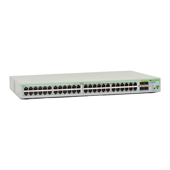
Overview AT-9000/52 The features of the AT-9000/52 Managed Layer 2 GE ecoSwitch include: ecoSwitch Figure 3 illustrates the front and back panels of the AT-9000/28SP Managed Layer 2 GE ecoSwitch. CONSOLE RS-232 Figure 3. AT-9000/52 Managed Layer 2 GE ecoSwitch Front and Back 52 port Gigabit Switch with 48 10/100/1000Base-T RJ-45 ports fixed configuration and 4 SFP slots RS-232 Console port with RJ-45 connector... -
Page 19: Twisted-Pair 10/100/1000Base-T Ports
24 and 48 twisted-pair 10/100/1000Base-T ports. In addition, four more twisted-pair ports are provided as part of four combo uplink ports on the AT-9000/28 and AT-9000/28SP and four additional individual twisted-pair uplinks ports are available on the AT-9000/52. -
Page 20: Sfp Transceiver Slots
21 Note For a list of supported SFP transceivers for the AT-9000 products, contact your Allied Telesis sales representative. Caution When you remove an SFP module from this product, the case temperature of the SFP may exceed 70 C (158 F). Exercise caution... -
Page 21: Combo Ports
Combo Ports Both the AT-9000/28 Managed Layer 2 GE ecoSwitch and AT-9000/28SP Managed Layer 2 GE ecoSwitch have four combo pairs of uplink ports, each consisting of one slot for a SFP transceiver and an redundant 10/ 100/1000 Base-T twisted-pair port. These combo ports are numbered 25 through 28 on both switches. -
Page 22: Rs-232 Console Port
Through the Console port you can connect to the switch and use Port the CLI-based AT-S100 Mangement Software user interface. Note For a list of supported SFP transceivers for the AT-9000/xx Managed Layer 2 GE ecoSwitches, contact your Allied Telesis sales representative. -
Page 23: Leds
LEDs System LEDs There are two system LEDs, the Power LED and SYS LED as shown in the following figure: The power supply port and system LED indications are described in Table 2, “Power Supply LED Indications”. Description Power RJ-45 Port LEDs The RJ-45 port LEDs are illustrated in Figure 6. -
Page 24: Figure 7. Front Panel Mode Led Select Button And Leds
Overview LINK LED The RJ-45 LINK LED function is described in Table 3. RJ-45 Mode LED You can choose the port status parameter (collision, speed, duplex or activity) by pushing the MODE LED SELECT button located next to the ecoFriendly button on the front panel. The status of this parameter will be displayed on each RJ-45 port Mode LED (shown in Figure 6 on page 23). -
Page 25: Table 4 Rj-45 Port Led Mode Indications
The RJ-45 Port Mode LED indications are described in Table 4. Each port MODE is selected by the MODE SELECT button. Table 4 RJ-45 Port LED MODE Indications RJ-45 Port Port MODE Indication Solid Green Solid Green Solid Right Amber Solid Green Flashing Green... -
Page 26: Sfp Leds
Overview SFP LEDs The SFP LINK/ACT LEDs are illustrated in Figure 8 and their function is described in Table 5: LINK/ACT LEDs Figure 8. SFP LINK/ACT LEDs Table 5. SFP LINK/ACT LED Indication LED Indication Solid Green A link is established on the port. Blinking Green Port is transmitting and/or receiving data. -
Page 27: Ecofriendly Button
ecoFriendly Button The front panel ecoFriendly button is illustrated in Figure 9 below. It enables the Low Power Mode (LPM) feature. This mode allows you to conserve power by turning off the port and MODE LEDs when they are not required. -
Page 28: Ethernet Switching Basics
Overview Ethernet Switching Basics An Ethernet switch interconnects network devices, such as workstations, printers, routers, and other Ethernet switches, so that they can communicate with each other by sending and receiving Ethernet frames. MAC Address Every hardware device on your network has a unique MAC address. This address is assigned to the device by the device’s manufacturer. -
Page 29: Duplex Mode
AT-9000 Managed Layer 2 GE ecoSwitch Series Installation Guide Duplex Mode Duplex mode refers to how an end node receives and transmits data. If an end node can receive or transmit data, but not both simultaneously, it is operating in what is referred to as half-duplex mode. If an end node can both receive and transmit data simultaneously, the end node is said to be operating in full-duplex mode. - Page 30 Overview sending data. This can occur under several circumstances. For example, if two end nodes are operating at different speeds, the switch, while transferring data between the end nodes, might need to instruct the faster end node to stop transmitting data to allow the slower end node to catch up.
-
Page 31: Chapter 2: Installing The Switch
Chapter 2 Installing the Switch This chapter contains the installation procedures for the switch. The chapter contains the following sections: “Reviewing Safety Precautions” on page 32 “Selecting a Site” on page 35 “Twisted-Pair and Fiber Optic Cable Specifications” on page 36 “Unpacking the Switch”... -
Page 32: Reviewing Safety Precautions
PDF document titled “Translated Safety Statements” (613-000990) posted on the Allied Telesis website at www.alliedtelesis.com. This document is also included with the CD that is shipped with the product. - Page 33 AT-9000 Managed Layer 2 GE ecoSwitch Series Installation Guide Pluggable Equipment. The socket outlet shall be installed near the equipment and shall be easily accessible. Caution: Air vents must not be blocked and must have free access to the room ambient air for cooling. Warning: Operating Temperature.
- Page 34 Chapter 2 - Installing the Switch Caution: When you remove an SFP module from this product, the case temperature of the SFP may exceed 70 C (158 F). Exercise caution when handling with unprotected hands.
-
Page 35: Selecting A Site
AT-9000 Managed Layer 2 GE ecoSwitch Series Installation Guide Selecting a Site Observe the following requirements when choosing a site for the switch: If you plan to install the switch in an equipment rack, check that the rack is safely secured and will not tip over. Devices in a rack should be installed starting at the bottom, with the heavier devices near the bottom of the rack. -
Page 36: Twisted-Pair And Fiber Optic Cable Specifications
Chapter 2 - Installing the Switch Twisted-Pair and Fiber Optic Cable Specifications Twisted-Pair Table 6 lists the cabling specifications for the 10/100/1000Base-T twisted- pair ports. Cable Specifications 10 Mbps 100 Mbps 1000 Mbps Optional The cable specifications for the optional SFP transceivers can be found in the transceiver data sheet available at www.alliedtelesis.com. -
Page 37: Unpacking The Switch
2. Place the switch on a level, secure surface. 3. Make sure the following components are included in your switch package. If any item is missing or damaged, contact your Allied Telesis sales representative for assistance. AT-9000 Managed Layer 2 GE ecoSwitch Series Installation Guide Note Store the packaging material in a safe location. -
Page 38: Installing The Switch On The Wall
Chapter 2 - Installing the Switch Installing the Switch on the Wall The AT-9000 Managed Layer 2 GE ecoSwitch can be mounted vertically on a wall using the two mounting brackets, screws, and anchors provided in the accessory kit. To wall-mount the switch, perform the following procedure: 1. -
Page 39: Figure 12. Positioning The Switch Onto The Wall With Mounting Screws
AT-9000 Managed Layer 2 GE ecoSwitch Series Installation Guide 5. Install the second mounting bracket on the other side of the switch using the four remaining Phillips head rack mount bracket screws. 6. Install two plastic anchors and two screws into the wall. The holes for the anchors should be 0.635 mm (0.25 in) in diameter and they should be drilled in the wall so that they are level with each other and spaced 465 mm (18.3 in) apart. -
Page 40: Installing The Switch In A Rack
Chapter 2 - Installing the Switch Installing the Switch in a Rack To install the switch in a standard 19-inch rack, perform the following procedure 1. Place the unit upside down on a level, secure surface. 2. Using a flat-head screwdriver, remove the snap-on plastic feet from 3. -
Page 41: Figure 15. Mounting The Switch In A Rack
AT-9000 Managed Layer 2 GE ecoSwitch Series Installation Guide 5. Install the second mounting bracket on the other side of the switch using the four remaining screws. 6. Mount the switch in the 19-inch rack using standard screws (not provided), as shown in Figure 15. Figure 15. -
Page 42: Installing Sfp Transceivers
Unnecessary removal or insertion of a transceiver can lead to premature failure. Ports 25 - 28 on both the AT-9000/28 and AT-9000/28SP Managed Layer 2 GE ecoSwitch are combo ports where the SFP slots are paired with twisted-pair ports. For operational information, refer to “Combo Ports”... -
Page 43: Figure 16. Remove Sfp Slot Dust Cap
AT-9000 Managed Layer 2 GE ecoSwitch Series Installation Guide Figure 16. Remove SFP Slot Dust Cap 3. Position the transceiver with the label facing up. 4. Slide the transceiver into the slot until it clicks into place as shown in Figure 17. -
Page 44: Figure 18. Removing The Sfp Dust Cap
Chapter 2 - Installing the Switch 5. Verify that the handle on the SFP transceiver is in the upright position, 6. Remove the dust plug from the SFP transceiver, as shown in 7. Repeat this procedure to install another SFP transceiver or go to as shown in Figure 18, to prevent inadvertently removing the transceiver. -
Page 45: Cabling The Twisted-Pair Or Fiber Optic Ports
Cabling the Twisted-Pair or Fiber Optic Ports Observe the following guidelines when connecting a twisted-pair or fiber optic cable to a port on the switch: The connector on the cable should fit snugly into the port on the switch. The tab on the connector should lock the connector into place. Because the twisted-pair ports on the switch are auto-MDI/MDI-X, any type of network device can be connected to a port on the switch using a straight-through twisted-pair cable. -
Page 46: Applying Ac Power
Chapter 2 - Installing the Switch Applying AC Power To apply AC power to the switch, perform the following procedure: 1. Plug the power cord into the AC power connector on the back panel of 2. Connect the other end of the power cord to an appropriate AC power 3. -
Page 47: Starting A Local Management Session
1. Connect the RJ-45 end of the management cable included with the shipping package to the Console Port. The Console Port is located on the front panel of the AT-9000/28 and AT-9000/28SP Managed Layer 2 GE ecoSwitches, as shown in Figure 20 and on the rear panel of the AT-9000/52 Managed Layer 2 GE ecoSwitch. - Page 48 Chapter 2 - Installing the Switch Note The port settings are for a DEC VT100 or ANSI terminal, or an equivalent terminal emulator program.
-
Page 49: Figure 21. Cli Prompt
AT-9000 Managed Layer 2 GE ecoSwitch Series Installation Guide 4. Press Enter. You are prompted for a user name and password. 5. To configure the switch settings, enter “manager” as the user name. The default password for manager access is “friend.” User names and passwords are case sensitive. -
Page 50: Assigning An Ip Address
Chapter 2 - Installing the Switch Assigning an IP Address You will need an IP address to access the Web user interface and to remotely manage the switch during a remote telnet connection. The procedure in this section explains how to find out if an IP address has already been assigned and if not, how to assign a static IP address to your AT-9000 Managed Layer 2 GE ecoSwitch. - Page 51 AT-9000 Managed Layer 2 GE ecoSwitch Series Installation Guide 5. Enter the IP address and mask with the following command: (9000/xx)(config-if)#ip address A.B.C.D/M where A.B.C.D/M specifies the IP address of the interface followed by a slash and a subnet mask. For example, you may set the address to 172.28.8.210/16 by entering the command: (9000/xx)(config-if)#ip address 172.28.8.210/16...
-
Page 52: Starting A Web Management Session
Chapter 2 - Installing the Switch Starting a Web Management Session The procedure in this section explains how to start a remote Web management session via one of the network ports on the switch. You can use a Web session to configure the switch’s operating parameters. This procedure assumes that you have assigned an IP address to the switch (refer to “Assigning an IP Address”... -
Page 53: Figure 23. At-9000 Ecoswitch Series Home Page
AT-9000 Managed Layer 2 GE ecoSwitch Series Installation Guide 3. Enter “manager” as the user name. The default password for manager access is “friend.” User names and passwords are case sensitive. The Home page is shown in Figure 23. Figure 23. AT-9000 ecoSwitch Series Home Page... -
Page 54: Warranty Registration
Chapter 2 - Installing the Switch Warranty Registration For warranty information, go to “Warranty” on page 14 or the Allied Telesis web site at www.alliedtelesis.com. -
Page 55: Chapter 3: Troubleshooting
This chapter contains information about how to troubleshoot the switch in the event a problem occurs. Note If you are unable to resolve a problem after following the instructions in this chapter, contact Allied Telesis Technical Support for assistance. Refer to “Contacting Allied Telesis” on page 14 for contact information. -
Page 56: Power Led Is Off
Chapter 3 - Troubleshooting Power LED is Off Check the PWR LED on the front of the switch. If the LED is off, indicating that the unit is not receiving power, do the following: Make sure the power cord is securely connected to the power source and to the AC connector on the back panel of the switch. -
Page 57: Twisted-Pair Port Link Led Is Off
Twisted-Pair Port Link LED is Off When a twisted-pair port on the switch is connected to a properly operating end node, the Link LED for the port should be on. If a Link LED is off, do the following: Verify that the ecoFriendly push button setting on the front panel is not set to the power saving mode by pressing the ecoSwitch push-button on the front panel. -
Page 58: Fiber Optic Port Link Led Is Off
Chapter 3 - Troubleshooting Fiber Optic Port Link LED is Off When a fiber optic port on the switch is connected to a properly operating end node, the Link LED for the port should be on. If a Link LED is off, do the following: Verify that the ecoFriendly push button setting on the front panel is not set to the power saving mode by pressing the ecoSwitch push- button... -
Page 59: Cannot Establish A Local (Out-Of-Band) Management Session
Cannot Establish a Local (Out-of-Band) Management Session If you are unable to establish a local (out-of-band) management session with the switch through the terminal port on the front panel, do the following: Check that the RJ-45 connector of the serial management cable is securely connected to the Console port on the switch and the DB-9 connector is connected to the RS-232 port on the terminal or personal computer. - Page 60 Chapter 3 - Troubleshooting...
-
Page 61: Appendix A: Technical Specifications
Appendix A Technical Specifications All specifications listed below are identical for the all the AT9000/xx switches except for the Weight and Power Consumption specifications. Physical Specifications Dimensions: AT-9000/28 AT-9000/28SP AT-9000/52 Weight: AT-9000/28 AT-9000/28SP AT-9000/52 Environmental Specifications Operating Temperature: Storage Temperature:... -
Page 62: Power Specifications
Appendix A: Technical Specifications Power Specifications AC Power Consumption: AT-9000/28 w/ ecoFriendly Mode AT-9000/28SP w/ ecoFriendly Mode AT-9000/52 w/ ecoFriendly Mode AC Input Electrical Ratings: Frequency: Safety and Electromagnetic Emissions Certifications Immunity Safety Quality and Reliability: Compliance Standards IEEE 802.3 – 10Base-T IEEE 802.3u –... -
Page 63: 10/100/1000Base-T Twisted-Pair Port Connectors
10/100/1000Base-T Twisted-Pair Port Connectors This section lists the pin signals for the 10/100/1000Base-T twisted-pair ports. Figure 24 illustrates the pin layout to an RJ-45 connector and port. Table 7 lists the RJ-45 pin signals when a twisted-pair port is operating in the MDI configuration. -
Page 64: Console Port Pinouts
Appendix A: Technical Specifications Table 9 lists the RJ-45 connector pins and their signals when a 1000Base-T port is operating at 1000 Mbps. Console Port Pinouts Table 10 lists the pin signals on the RJ-45 style serial terminal port. Table 9. RJ-45 1000Base-T Connector Pinouts Pair 1. -
Page 65: Appendix A: Cleaning Fiber Optic Connectors
Appendix A Cleaning Fiber Optic Connectors This section describes how to clean fiber optic connections. The fiber optic connector consists of a fiber optic plug and its adapter. The end of the fiber optic cable is held in the core of the ferrule in the plug. Light signals are transmitted through the core of the fiber. -
Page 66: Using A Cartridge-Type Cleaner
Appendix A: Cleaning Fiber Optic Connectors Using a Cartridge-Type Cleaner Fiber optic cartridge cleaners are available from many vendors and are typically called “cartridge cleaners,” as shown inFigure 27. To clean a fiber optic connector using a cartridge cleaner, perform the following procedure. -
Page 67: Figure 28. Rubbing The Ferrule Tip On The Cleaning Surface
AT-9000 Managed Layer 2 GE ecoSwitch Series Installation Guide Figure 28. Rubbing the Ferrule Tip on the Cleaning Surface Note Rub the ferrule tip on the cleaning surface in one direction only. 3. When you reach the end of the cleaning surface, pick up the ferrule tip, rotate and place it at the top and rub downwards at least two times. -
Page 68: Using A Swab
Appendix A: Cleaning Fiber Optic Connectors Using a Swab Specially treated swabs, or stick cleaners, are available for cleaning inside connector adapters or hard-to-reach ferrule tips. These swabs, often referred to as “lint free” or “alcohol free” swabs are available from many vendors, as shown in Figure 29 on page 68. -
Page 69: Figure 30. Cleaning A Recessed Ferrule
AT-9000 Managed Layer 2 GE ecoSwitch Series Installation Guide To clean a recessed ferrule using a swab, perform the following procedure. 1. Insert the swab into the adapter as shown in Figure 30. Rub the ferrule tip with the swab. Figure 30. - Page 70 Appendix A: Cleaning Fiber Optic Connectors...
Need help?
Do you have a question about the AT-9000/28 and is the answer not in the manual?
Questions and answers