
Related Manuals for Syscom Video HD Mini Cube


Summary of Contents for Syscom Video HD Mini Cube
-
Page 1: Network Camera
INSTRUCTION MANUAL HD Mini Cube Network Camera Please read this manual thoroughly before use, and keep it handy for future reference. -
Page 2: Explanation Of Graphical Symbols
WARNING TO REDUCE THE RISK OF FIRE OR ELECTRIC SHOCK, DO NOT EXPOSE THIS PROCUCT TO RAIN OR MOISTURE. DO NOT INSERT ANY METALLIC OBJECT THROUGH THE VENTILATION GRILLS OR OTHER OPENNINGS ON THE EQUIPMENT. CAUTION EXPLANATION OF GRAPHICAL SYMBOLS The lightning flash with arrowhead symbol, within an equilateral triangle, is intended to alert the user to the presence of uninsulated "dangerous voltage"... -
Page 3: Fcc Compliance Statement
FCC COMPLIANCE STATEMENT INFORMATION TO THE USER : THIS EQUIPMENT HAS BEEN TESTED AND FOUND TO COMPLY WITH THE LIMITS FOR A CLASS A DIGITAL DEVICE, PURSUANT TO PART 15 OF THE FCC RULES. THESE LIMITS ARE DESIGNED TO PROVIDE REASONABLE PROTECTION AGAINST HARMFUL INTERFERENCE WHEN THE EQUIPMENT IS OPERATED IN A COMMERCIAL ENVIRONMENT. -
Page 4: Important Safety Instructions
IMPORTANT SAFETY INSTRUCTIONS 1. Read these instructions. 2. Keep these instructions. 3. Heed all warnings. 4. Follow all instructions. 5. Do not use this apparatus near water. 6. Clean only with dry cloth. 7. Do not block any ventilation openings. Install in accordance with the manufacturer’s instructions. -
Page 5: Table Of Contents
Contents 1. Description ------------------------------------------------------------------6 1.1 Components - ------------------------------------------------------------------------------------------ 7 1.2 Key Features - ------------------------------------------------------------------------------------------ 7 1.3 Over View ---- ------------------------------------------------------------------------------------------ 8 2. Installation ----------------------------------------------------------------- 10 2.1 Connection ---- ----------------------------------------------------------------------------------------- 10 2.2 Network Connection and IP Assignment ---------------------------------------------------------- 12 3. Operation -------------------------------------------------------------------- 13 3.1 Access from a browser -------------------------------------------------------------------------------- 13 3.2 Access from the internet ------------------------------------------------------------------------------ 14 3.3 Setting the admin password over a secure connection ------------------------------------------- 14... -
Page 6: Description
1. Description The Network Camera supports the network service for a sensor image with progressive scan, which can be monitored on a real-time screen regardless of distances and locations. By using its dedicated program, many users are able to have an access to the Network Camera at once or a single user can monitor various network cameras at the same time. -
Page 7: Components
1.1 Components The system comes with the following components: Cube Camera Installation CD Installation Guide Stand Clamp Adaptor NOTE: Check your package to make sure that you received the complete system, including all components shown above. 1.2 Key Features • Brilliant video quality The Network Camera offers the highly efficient H.264 video compression, which drastically reduces bandwidth and storage requirements without compromising image quality. -
Page 8: Overview
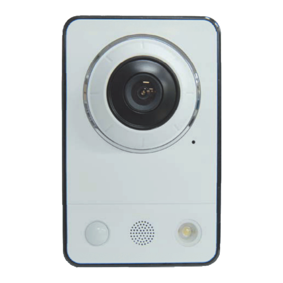
• PIR Sensor Complementing the video motion detection capability of the cameras, the full-featured NCT-2211 and NCT- 2221 additionally integrate a PIR Sensor for detecting movements - even in the dark. • Illumination NCT-2211 and NCT-2221 offer a white LED for illuminating the scene automatically at an event or when requested by the user. - Page 9 • Rear View Name Description NCT-2211/NCT-2221 is equipped with a PIR Sensor that has a maximum PIR Sensor range of 5 meters for detecting movement in the dark. NCT-2211/NCT-2221 is equipped with a Microphone and Speaker. Two- Microphone/Speaker way audio support allows for remote users to listen in on an area and communicate with visitors or intruders.
-
Page 10: Installation
2. Installation 2.1 Connection • Connecting to the RJ-45 Connect a standard RJ-45 cable to the network port of the network camera. Generally a cross-over cable is used for directly connection to PC, while a direct cable is used for connection to a hub. - Page 11 Notes: 1. WPS may not work if your AP is configured with a "hidden" SSID. 2. If any WPS-enabled AP is not detected, the camera will search APs for 60 seconds after pressing the WPS button, and if the camera still can not detect an AP after 1 minute, the wireless setup will be cancelled.
-
Page 12: Network Connection And Ip Assignment
2.2 Network Connection and IP assignment The Network Camera supports the operation through the network. When a camera is first connected to the network it has no IP address. So, it is necessary to allocate an IP address to the device with the “Smart Manager”... -
Page 13: Operation
3. Operation The Network Camera can be used with Windows operating system and browsers. The recommended browsers are Internet Explorer, Safari, Firefox, Opera and Google Chrome with Windows. NOTE: To view streaming video in Microsoft Internet Explorer, set your browser to allow ActiveX controls. -
Page 14: Access From The Internet
3.2. Access from the internet Access from the internet once connected, the Network Camera is accessible on your local network (LAN). To access the network camera from the Internet you must configure your broadband router to allow incoming data traffic to the network camera. To do this, enable the NAT-traversal feature, which will attempt to automatically configure the router to allow access to the network camera. -
Page 15: Live View Page
3.4 Live View Page The live view page comes in eight screen modes: 1600x1200, 1280x1024, 1280x720, 800x600, 720x480(576), 640x480, 352x240(288), and 320x240. Users are allowed to select the most suitable one out of those modes. Please, adjust the mode in accordance with your PC specifications and monitoring purposes. - Page 16 The digital zoom activates a zoom-in or zoom-out function for video image on the live screen. The Full Screen button causes the video image to fill the entire screen area. No other windows will be visible. Press the 'Esc' button on the computer keyboard to cancel full screen view.
-
Page 17: Network Camera Setup
3.5 Network Camera Setup This section describes how to configure the network camera, and is intended for product Administrators, who have unrestricted access to all the Setup tools; and Operators, who have access to the settings for Basic, Live View, Video & Image, Audio, Event, and System Configuration. You can configure the network camera by clicking Setup in the top right-hand corner of the Live View page. -
Page 18: Users
1) Users User access control is enabled by default. An administrator can set up other users, by giving these user names and passwords. It is also possible to allow anonymous viewer login, which means that anybody may access the Live View page, as described below: The user list displays the authorized users and user groups (levels): User Group Authority... -
Page 19: Network
2) Network The network camera supports both IP version 4 and IP version 6. Both versions may be enabled simultaneously, and at least one version must always be enabled. When using IPv4, the IP address for the network camera can be set automatically via DHCP, or a static IP address can be set manually. If IPv6 is enabled, the network camera receive an IP address according to the configuration in the network router. -
Page 20: Video & Image
3) Video & Image • Sensor Setting Capture Mode: Choose Capture Mode you wish to use from the drop-down list: 1600x1200 Max 15fps: Capture resolution is 1600x1200 and Maximum frame is 15. 1280x720 Max 30fps: Capture resolution is 1280x720 and Maximum frame is 30. 800x800 Max 30fps: Capture resolution is 800x600 and Maximum frame is 30. - Page 21 H.264 MP(Main Profile): Primarily for low-cost applications that requires additional error robustness, this profile is used rarely in videoconferencing and mobile applications, it does add additional error resilience tools to the Constrained Baseline Profile. The importance of this profile is fading after the Constrained Baseline Profile has been defined.
-
Page 22: Audio
• Stream2 Setting Sometimes the image size is large due to low light or complex scenery. Adjusting the frame rate and quality helps to control the bandwidth and storage used by the Motion JPEG video stream in these situations. Limiting the frame rate and quality optimizes bandwidth and storage usage, but may give poor image quality. - Page 23 • Audio Setting Enable audio: Check the box to enable audio in the video stream. Compression type: Select the desired audio Compression format, G711. Sample rate: Select the required Sample rate (number of times per second the sound is sampled). The higher the sample rate, the better the audio quality and the greater the bandwidth required.
-
Page 24: Date & Time
5) Date & Time • Current Server Time It displays the current date and time (24h clock). The time can be displayed in 12h clock format in the overlay (see below). • New Server Time Select your time zone from the drop-down list. If you want the server clock to automatically adjust for daylight savings time, select the “Automatically adjustment for daylight saving time changes”. -
Page 25: Video & Image
3.5.2 Video & Image Live View • Video Input Mode Video Mode: Choose Video Mode you wish to use from the drop-down list: NTSC or PAL... - Page 26 Basic Refer to “3.5.1 Basic Configuration > Video & Image” for more details.
- Page 27 Image • Image Appearance This page provides access to the advanced image settings for the network camera. Brightness: The image brightness can be adjusted in the range 1-10, where a higher value produces a brighter image. Color level: Select an appropriate level by entering a value in the range 1-10. Lower values mean less color saturation.
- Page 28 AE & AWB to set the exposure and white balance of the network camera. This page provides access • Exposure Control Configure the exposure settings to suit the image quality requirements in relation to lighting consideration. Mode: Supports exposure modes to control the amount of light detected by the camera sensor based on settings for light conditions.
- Page 29 From the drop-down list, select the white balance setting suitable for the lighting used for your camera. The available options are: Automatic: Automatic identification and compensation for the light source color. This can be used in most situations and is the recommended setting. Fixed Incandescent: Fixed color adjustment, ideal for a room with incandescent (a glow) lighting and good for a normal color temperature around 2600K.
- Page 30 To create a mask window, follow steps: Click the right button of mouse to see the mouse menu. Select New Privacy Mask in the mouse menu. Click and drag mouse to designate a mask window area. You can also modify or delete a mask window index. Select an index and then, modify items or delete button.
-
Page 31: Audio
3.5.3 Audio Refer to “3.5.1 Basic Configuration > Audio” for more details. -
Page 32: Event
3.5.4 Event 1) Event-In On Boot This is used to trigger the event every time the Network Camera is started. Select “Enable” to activate the motion event. - Page 33 Manual Trigger This option makes use of the manual trigger button provided on the live view page, which are used to start or stop the event type manually. Alternatively the event can be triggered via the product's API (Application Programming Interface).
- Page 34 Motion Motion detection is used to generate an alarm whenever movement occurs (or stops) in the video image. A total of 8 Motion and/or Mask windows can be created and configured. Motion is detected in defined Motion windows, which are placed in the video image to target specific areas.
- Page 35 • Motion Detection Setting The behavior for each window is defined by adjusting the Threshold and Sensitivity, as described below. A motion index is a set of parameters describing Window Name, Type, Threshold, Sensitivity, and Dwell Time. Window Types is one of Motion and Mask windows. Threshold: Sets up the threshold for the motion detection.
- Page 36 PIR The NCT-2211 and NCT-2221 are also able to detect motion using the PIR Sensor. Since the PIR Sensor can detect a moving infrared object such as a person in the dark, it can be used as an intruder alarm when, for example, a thief tries to break into a building at night.
- Page 37 Audio Detection The NCT-2211 and NCT-2221 are also able to detect change of the ambient voice using a built-in microphone. Audio detection can be used to measure change in the ambient voice. • Audio Detection Setting Select the sensitivity from the drop-down menu. Audio Detection Level: Be used to adjust the sensitivity of the audio level from 10-100%.
-
Page 38: Event-Out
2) Event-Out SMTP(E-Mail) The Network Camera can be configured to send event and error email messages via SMTP (Simple Mail Transfer Protocol). • SMTP(E-Mail) Setting Select “Enable” to activate the SMTP operation. Mail Server / Port: Enter the host names (or IP addresses) and port numbers for your mail server in the fields provided, to enable the sending of notifications and image email messages from the camera to predefined addresses via SMTP. - Page 39 Login Method: Set the Weakest method allowed to the highest/safest method supported by the mail server. The most secure method is listed in the drop-down list: Login / Plain • SMTP(E-Mail) Receiver Receiver: Enter an email address. You can also register the e-mail address of recipients up to 8.
- Page 40 • JPEG Setting Pre-event: A pre-event buffer contains images from the time immediately preceding the event trigger. These are stored internally in the server. This buffer can be very useful when checking to see what happened to cause the event trigger. Check the box to enable the pre-trigger buffer, enter the desired total length in seconds, minutes or hours, and specify the required image frequency.
- Page 41 Audio Alert When the network camera detects an event, it can output a predefined audio data to external speaker. Check the box to enable the service. • Audio Alert Setting To use the audio alert with the Network camera, an audio data file made by user must be uploaded from your PC.
- Page 42 Audio Recorder To use Audio Recorder tool to make an audio file for Audio Alert function, you must install the Syscom Virtual Management System on the installation CD at first. The NC Titanium program (Start>All Programs>Syscom Virtual Management System>Tools> ARecorder) in your PC, the ARecorder window will be displayed as below. The description of each button in the ARecorder window follows.
- Page 43 ▼ Record When the network camera detects an event, it can record video stream in the Micro SD Memory (not supplied) or NAS (Network Attached Device) as a storage device. Check the box to enable the service. • Record Setting Overwrite: Click checkbox to overwrite the storage device.
- Page 44 Note2: Network File System (NFS) is a network file system protocol, allowing a user on a client computer to access files over a network in a manner similar to how local storage is accessed. NFS, like many other protocols, builds on the Open Network Computing Remote Procedure Call (ONC RPC) system.
- Page 45 ▼ Light The LED on the front of the camera can be set to flash at a configurable interval when an event is triggered. From the Activate drop down menu, select a Light level which the LED will brighten to. Select “Enable”...
-
Page 46: Event Map
3) Event Map The event map allows you to change the settings and establish a schedule for each event trigger from the Network Camera. You can register the event map up to max. 15. Click Add button to make a new event map and you can see a popup window as below. - Page 47 • General Enter the name for a new event map. • Event In Select an event type in the drop down list. • Event Out E-mail: Select email addresses you want to send via email that an event has occurred. FTP: Select checkbox beside FTP to record and saves images to an FTP server when an event has occurred.
-
Page 48: System
3.5.5 System 1) Information You can enter the system information. This page is very useful when you refer device information after installation. • Device Name Configuration Enter the device name. • Location Configuration Enter the location information. You can enter that by four. -
Page 49: Security
2) Security Users User access control is enabled by default, when the administrator sets the root password on first access. New users are authorized with user names and passwords, or the administrator can choose to allow anonymous viewer login to the Live View page, as described below: •... - Page 50 HTTPS For greater security, the Network Camera can be configured to use HTTPS (Hypertext Transfer Protocol over SSL (Secure Socket Layer)). That is, all communication that would otherwise go via HTTP will instead go via an encrypted HTTPS connection. •...
- Page 51 IP Filtering Checking the Enable IP address filtering box enables the IP address filtering function. Up to 256 IP address entries may be specified (a single entry can contain multiple IP addresses). Click the Add button to add new filtered addresses. When the IP address filter is enabled, addresses added to the list are set as allowed or denied addresses.
-
Page 52: Date & Time
3) Date & Time • Current Server Time It displays the current date and time (24h clock). The time can be displayed in 12h clock format in the overlay (see below). • New Server Time Select your time zone from the drop-down list. If you want the server clock to automatically adjust for daylight savings time, select “Automatically adjustment for daylight saving time changes”. -
Page 53: Network
4) Network Setting in regard to network can be executed. Settings for IP, DNS, Host Name, Port, and ARP/Ping can be established, along with setting for DDNS, uPnP, QoS, Zeroconfig, Bonjour, Live Push, Hole Punching, and wireless. - Page 54 Basic • IP Address Configuration: Obtain IP address via DHCP: Dynamic Host Configuration Protocol (DHCP) is a protocol that lets network administrators centrally manage and automate the assignment of IP addresses on a network. DHCP is enabled by default. Although a DHCP server is mostly used to set an IP address dynamically, it is also possible to use it to set a static, known IP address for a particular MAC address.
- Page 55 • Gateway Priority Wireless: In case of network connection through the wireless AP Wire: In case of a wired network connection. DDNS • Internet DDNS(Dynamic Domain Name Service) When using the high-speed Internet with the telephone or cable network, users can operate the Network Camera even on the floating IP environment in which IPs are changed at every access.
- Page 56 RTP Have a setting for sending and receiving an audio or video on a real-time basis. These settings are the IP address, port number, and Time-To-Live value to use for the media stream(s) in multicast H.264 format. Only certain IP addresses and port numbers should be used for multicast streams. For more information, please see the online help.
- Page 57 UPnP The Network Camera includes support for UPnP™. UPnP™ is enabled by default, and the Network Camera then is automatically detected by operating systems and clients that support this protocol. Note: UPnP™ must be installed on your workstation if running Windows XP. To do this, open the Control Panel from the Start Menu and select Add/Remove Programs.
- Page 58 QoS Quality of Service (QoS) provides the means to guarantee a certain level of a specified resource to selected traffic on a network. Quality can be defined as a maintained level of bandwidth, low latency, and no packet losses. The main benefits of a QoS-aware network are: The ability to prioritize traffic and thus allow critical flows to be served before flows with lesser priority.
- Page 59 • Auto Traffic Control Set a limitation on user network resources by designating the maximum bandwidth. Maximum bandwidth: In case of sharing other network programs or equipment, it is possible to set a limitation on the maximum bandwidth in the unit of Mbit/s or kbit/s. Auto frame rate: Selected if not influenced by a network-related program or equipment without a limitation on the network bandwidth.
- Page 60 • NAT traversal Settings Enable: when enabled, the network camera attempt to configure port mapping in a NAT router on your network, using UPnP™. Note that UPnP™ must be enabled in the Network Camera (see System>Network>UPnP). automatic setting: The Network Camera automatically search for NAT routers on your network.
- Page 61 Zeroconfig Zeroconfig allows the network camera to create and assign IP address for network cameras and connect to a network automatically. Zero configuration networking (zeroconf), is a set of techniques that automatically creates a usable Internet Protocol (IP) network without manual operator intervention or special configuration servers. Zero configuration networking allows devices such as computers and printers to connect to a network automatically.
- Page 62 Bonjour The network camera includes support for Bonjour. When enabled, the network camera is automatically detected by operating systems and clients that support this protocol. Note: Bonjour - Also known as zero-configuration networking, Bonjour enables devices to automatically discover each other on a network, without having to enter IP addresses or configure DNS servers.
- Page 63 Live Push • Live Push Configuration When you activate this function, the network camera as a client can transfer audio, video and event data to the registered server. The network camera and server use RTP/RTSP as the protocol for the actual transport of audio/video data.
- Page 64 Hole Punching • Hole Punching Configuration Rendezvous Server URL: Enter the third-party server’s URL that uncovers external and internal address information. ID/Password: Enter ID and Password. The network camera will ask them whenever you access the Rendezvous Server. Note: Hole punching is a computer networking technique for establishing communications between two parties in separate organizations who are both behind restrictive firewalls.
- Page 65 Wireless(NCT-2211 only) Wireless settings in the NCT-2211 must be the same as the access point or ad-hoc device. When changing the settings, they should always be made first in the camera and then in the wireless access point. This ensures that the camera is always accessible when making changes. •...
-
Page 66: Language
The NCT-2211 have three security options: • WPA-/WPA2-PSK • WPA-/WPA2-Enterprise • WEP WPA-/WPA2-Enterprise is more secure than WPA-/WPA2-PSK, which in turn is more secure than WEP. 5) Language It will be able to select a user language. The type of language it will be able to select is the English, the French, the German, the Spanish and the Italian. -
Page 67: Support
Default: The default button should be used with caution. Pressing this will return all of the Network Camera's settings to the factory default values (including the IP address). • Update Server Carry out the upgrade by importing an upgrade file and pressing the Upgrade button. During the upgrade, do not turn off the power of the Network Camera. -
Page 68: About
Parameter List: Click the Parameter List button to see the unit’s parameters and their current settings. 3.5.6 About The following website will provide the support information for the Network Camera information and operation. 3.6 Playback The Playback window contains a list of recordings made to the memory card. It shows each recording's start time, length, the event type used to start the recording, calendar and time slice bar indicates if the recording is existed or not. - Page 69 The description of playback window follows. (1) Video Screen You can see the video screen when playing the video clip in the Micro SD memory (2) Playback Buttons To view a recording data in the SD local storage, select it from the list and click the Playback buttons. Go to the first: go to the beginning of the video clip.
-
Page 70: Help
3.7 Help The Help information window will be provided as a popup window so that users can open and read it without a need for log-in. It will offer a description on setting and Help page by which users can manipulate the Network Camera without a reference to the manual. -
Page 71: Resetting To The Factory Default Settings
3.8 Resetting to the factory default settings To reset the Network Camera to the original factory settings, go to the Setup>System> Maintenance web page (described in “3.5.4 System > Maintenance”) or use the Reset button on the network camera, as described below: •... -
Page 72: Appendix
4. Appendix 4.1 Troubleshooting Troubleshooting if problems occur, verify the installation of the Network Camera with the instructions in this manual and with other operating equipment. Isolate the problem to the specific piece of equipment in the system and refer to the equipment manual for further information. Problems/Symptoms Possible Causes or Corrective Actions The camera cannot be accessed... -
Page 73: Preventive Maintenance
4.2 Preventive Maintenance Preventive maintenance allows detection and correction of minor that faults before they become serious and cause equipment failure. Every three-month, perform the following maintenance. Inspect all connection cables for deterioration or other damage. Clean components with a clean damp cloth. Verify that all the mounting hardware is secure. -
Page 74: Product Specification
4.3 Product Specification Main Item Specification Image sensor 1/4” Progressive scan RGB CMOS Active Array 1600(H) x 1200(V) Lens Fixed 2.6mm Lens, F1.8 80.7°(H) x 58.7(V) x 103.2°(D) Angle of View Min. illumination Color: 1Lux(LED Off), 0Lux (LED On) Shutter Speed 1/20,000 ~ 1/30 (Slow shutter 1/15, 1/8 and 1/4) -. -
Page 75: System Requirement For Web Browser
RJ-45 10BASE-T/100BASE-TX Ethernet NCT-2211 only: Built-in IEEE 802.11b/g/n wireless LAN NCT-2211, NCT-2221 only: Passive infrared (PIR) motion sensor with configurable PIR Sensor sensitivity. Max range: 5m, 60°(H) x 20°(V) NCT-2211 and NCT-2221 only: Illumination LED White illumination LED: 1 W Operating Temperature 0°C ~ 40°C Operation Humidity... - Page 76 HD CUBE CAMERA...
Need help?
Do you have a question about the HD Mini Cube and is the answer not in the manual?
Questions and answers