Ampac ZoneSense PLUS Installation & Commissioning
Fire detection and evacuation solutions that save lives.
Hide thumbs
Also See for ZoneSense PLUS:
- Installation, commissioning & operation (50 pages) ,
- Operation & programming manual (36 pages) ,
- Installation & commissioning (28 pages)

Related Manuals for Ampac ZoneSense PLUS


Summary of Contents for Ampac ZoneSense PLUS
- Page 1 Fire detection and evacuation solutions that save lives. ZoneSense PLUS Installation & Commissioning MAN1563-5...
-
Page 2: Table Of Contents
General Requirements ........................4 References ........................... 4 Symbols ............................4 System Overview ..........................5 ZoneSense PLUS Description ....................... 6 Placing the Basic System into Operation ..................... 7 Unpacking ............................ 7 Anti-Static Precautions ......................... 7 Working On The System ....................... 7 The Cabinet .......................... - Page 3 MAN1563-5 6.8.2 Fault Output (TB5 3 / 4) .......................24 Outputs – Volt Free Relay Programmable ..................24 6.9.1 Alarm Output (TB5 5 / 6 / 7)....................24 6.10 Outputs – Volt Free Relay Non-Programmable................24 6.10.1 Fault Output (TB5 8 / 9 / 10) ....................24 6.11 Auxiliary Power Output (TB12 1 / 2).....................24 6.11.1...
-
Page 4: About This Manual
1 About This Manual 1.1 Introduction This manual contains all the information required to install, commission and operate the ZoneSense PLUS Fire Alarm Control Panel (FACP) and is only available to and for the use of personnel engaged in its installation, commissioning and operation. -
Page 5: System Overview
MAN1563-5 2 System Overview The ZoneSense PLUS 4 and 8 zone FACP complies with the highest level of approval for any applicable code and can be connected to an appropriate Fire Service monitoring facility. As a Minimum, the conventional panel meets the following Standards;... -
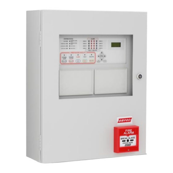
Page 6: Zonesense Plus Description
MAN1563-5 3 ZoneSense PLUS Description The ZoneSense PLUS Fire Alarm Control Panel (FACP) is approved to AS4428 and is available in ABS (BX1) or metal cabinets (BX20) with either four (4) or eight (8) zone conventional detection circuits. The 2 line LCD display allows the user to view system status, faults/isolates, prompts for system commands; and guides the user during on-site programming. -
Page 7: Placing The Basic System Into Operation
MAN1563-5 4 Placing the Basic System into Operation 4.1 Unpacking Carefully unpack the ZoneSense PLUS The package should include: ➢ Main Card, with all controls and indicators mounted directly onto it; ➢ a switch-mode power supply; ➢ 2 X 12 Volt batteries connected in series. -
Page 8: Mounting The Cabinet
3 mm 12 mm R 6mm. Tap lightly around the rim of the knockout Figure 2: Example ZoneSense PLUS Mounting & Removing Knockouts TO REMOVE FRONT DOOR REMOVING SLIDE THE DOOR UP AND KNOCKOUTS AWAY FROM THE... -
Page 9: Pcb Removal / Replacement
MAN1563-5 5 PCB Removal / Replacement If the PCB’s have to be removed the following precautions should be observed; ➢ Removing the door will provide better access to the boards and ensure the hinges are not accidentally stressed. ➢ Personal anti- static procedures must be followed. ➢... -
Page 10: Power Supplies And Ac Mains Installation
Important: Under no circumstances should the ZoneSense PLUS panel be operated without the Power Supply correctly mounted in the enclosure and the retaining screws securely tightened. 5.1.4 Connecting the Mains Earth All earth cabling shall be terminated to the panel Chassis Earth Terminal in a star configuration. -
Page 11: Connecting The Mains Power To The Power Supply
MAN1563-5 5.1.5 Connecting the Mains Power to the Power Supply NEUTRAL (BLUE) EARTH (GREEN) ACTIVE (BROWN) (AC IN) MAINS CABLE COMBINED MAINS SWITCH & MAINS INDICATION F1: 2A Fuse PROTECTIVE PERSPEX COVER CHASSIS EARTH DANGER AC ON TERMINAL NOTE: MAINS CABLE SHOULD BE NO LESS THAN 0.75mm CAUTION:... -
Page 12: Battery Charger
MAN1563-5 5.2 Battery Charger The battery charger is an integral part of the Power Supply and is capable of ➢ Recharging standard sized system batteries within 24 hours ➢ Detecting a missing, damaged or undercharged battery ➢ Protecting the battery against reverse or a short circuit condition ➢... -
Page 13: Main Control Board
MAN1563-5 6 Main Control Board The Main Control Card and its front display panel combined with the Power Supply / Battery Charger and batteries form the basis for the ZoneSense PLUS FACP. ASSEMBLED BRIDGE SHIELD BRIDGE DECAL Figure 7: Exploded view of the Control Panel... -
Page 14: Connector Numbering
MAN1563-5 TP31 TP30 TP61 TP60 TP59 TP58 TP37 TP39 TP36 TP35 TP34 TP33 TP32 TP24 TP23 TP22 TP21 TP20 TP19 TP27 TP25 TP29 TP18 TP17 TP10 TP26 TP28 TP16 TP15 TP14 TP13 TP12 TP11 EARTH DISABLE TP40 TP 1 to 44 +Z8- +Z7- +Z6-... -
Page 15: Terminal Block Numbering
MAN1563-5 6.2 Terminal Block Numbering Terminal Block TP Number AS4428 COMMUNICATIONS EXTERNAL TB2/1 RS485 + RS485 - Shield INPUTS TB3/1 Common Door Switch (monitored) Manual Call Point (monitored) Fault Input (monitored) ZONES ( 25mA / Zone ) TB13/1 + Zone 1 - Zone 1 + Zone 2 - Zone 2... - Page 16 MAN1563-5 Ohms Warn Sys Bell Ohms Note: If a diode is NOT fitted internally to the Bell / Sounder a diode MUST be fitted as shown - fit 1N4004 or similar Figure 10: General Wiring Diagram ZoneSense PLUS...
-
Page 17: Earth Monitoring
Earth Fault LED on the control panel. Note: If ZoneSense PLUS is connected to a third party system which has earth monitoring and it’s earth monitoring is being affected by ZoneSense PLUS even after being disabled through programming the resistor R22 on the Main Card in ZoneSense PLUS can be removed. -
Page 18: Inputs - Monitored (Tb3)
MAN1563-5 6.5 Inputs – Monitored (TB3) 6.5.1 Common Terminal (TB3 Com) The COM terminal is used as the common for the following three 0v potential inputs. 6.5.2 Door Switch Input (TB3 Com / 1) This optional input is used for connecting the FACP’s door switch. Connection is to TB3 COM & 1 6.5.3 MCP (TB3 Com / 2) The optional external MCP I/P is monitored for normal operation and must be mapped to a particular zone. -
Page 19: Detector Zones (Tb13 & Tb14)
MAN1563-5 6.6 Detector Zones (TB13 & TB14) Zone circuit connections are made directly to TB13 & TB14 on the Main Card and if screened cabling is used the screen is terminated at the panel's chassis earth terminal. All zones can be programmed to operate in one of the 5 different configuration modes each with a reset time in the order of >... - Page 20 Note: EOL type (capacitive / resistive) and value are set in the Programming Menu Note: A maximum of 40 ZoneSense PLUS compatible Optical / Heat and Ionisation Detectors or Manual Call Points can be fitted to each circuit and mixed in any order.
-
Page 21: Outputs - Monitored (Tb4)
MAN1563-5 6.7 Outputs - Monitored (TB4) 6.7.1 Alarm Outputs The panel has 4 dedicated individually monitored outputs which are; ➢ rated at 500mA @ 24VDC nominal; ➢ protected against short circuits; ➢ Monitored for open and short circuit conditions even when an output is active. The monitoring operates on a reverse voltage principal and will indicate a fault within 60 seconds. -
Page 22: Warning System Output (Tb4 3 / 4)
MAN1563-5 6.7.3 Warning System Output (TB4 3 / 4) Switched 24VDC. Operated by an alarm from a non-isolated zone. The “Warning System Isolate” switch controls this output. When pushed the “Warning System” output is inhibited and the LED is illuminated. If pushed again the output is toggled back to the normal state. Re-activates the audible fault indication if the output is still in fault and left isolated for longer than 8 hours. -
Page 23: Conventional Sounder Circuit Wiring (Tb4)
MAN1563-5 6.7.6 Conventional Sounder Circuit Wiring (TB4) Each of the four alarm outputs can also be configured to drive a conventional sounder circuit. Ohms Ohms Ohms Ohms Sounder Sounder Sounder Sounder + Z7 - + Z8 - + 1 - + 2 - + 3 - + 4 -... -
Page 24: Outputs - Monitored Open Collector (Tb5)
MAN1563-5 6.8 Outputs – Monitored Open Collector (TB5) Definition: A monitored open collector output for user connections. Via the front panel it is possible to program which zones will operate any of the outputs. 6.8.1 Alarm Output (TB5 1 / 2) The output operates in parallel to the Alarm Output relay and energises if a zone is not isolated and is in the alarm condition. -
Page 25: Reset Terminal / Buzzer Output. (Tb12 / 3)
MAN1563-5 6.11.1 Reset Terminal / Buzzer Output. (TB12 / 3) An output rated at 24VDC @ 100mA that can be configured to the user’s requirement to provide either of the following 2 functions: Reset. Reset is used to reset field devices such as beam detectors that is Reset switches negative for a period of 1.2 seconds on operation of the “Reset”... -
Page 26: Expanding The Facp With Compatible Ancilliary Board
➢ LED Annunciator Master BRD25 GIB – E ➢ Remote Relay Board BRD25EWRB – B Note: To add or remove Add-On’s from the FACP go to the SYSTEM and PROGRAM Menus. Note: Refer to manual MAN1565 “ZoneSense Plus Add-On’s” for full installation details. -
Page 27: Installation And Wiring Of Add On Cards And Boards
MAN1563-5 7.1 Installation and Wiring of Add On Cards and Boards Figure 17: Add On Card and Board Positioning Within the ABS FACP... -
Page 28: Internal Communications Connector (Rs485)
MAN1563-5 7.2 Internal Communications Connector (RS485) PCB mounted connectors provide serial communications to internal ancillary boards. CN9 on the Main Card cables to CN5 or 6 on the Agent Release Card or CN1 or 2 on the “Add on” front panel cards and CN5 on the Main Card cables to CN1 or 2 on the back pan boards Front Panel Front Panel... -
Page 29: Battery Capacity Calculation
MAN1563-5 8 Battery Capacity Calculation The standby power source capacity, or battery capacity, determines how long the system will continue to operate in the event of the loss of the primary power source. It therefore becomes necessary to calculate the battery and hence power supply / battery charger capacity required for each installation. -
Page 30: Power Supply & Battery Calculator
MAN1563-5 8.3 Power Supply & Battery Calculator Criteria Example Iq Calculation Iq Calculation Panel Configuration No Off X mA = Iq No Off X mA = Iq Basic 4 zone gas panel Basic 8 zone gas panel Interface Cards/Boards Sounder Board Brigade Board Input Board Fire Fan Module... -
Page 31: Primary Power Source Calculations
MAN1563-5 Criteria Example Battery capacity at end of ( Iq x 24 ) + ( Ia x 0.5 ) ( Iq x 24 ) + Fc( Ia x 0.5 ) battery life Note: the figure of 24 Fc – capacity de-rating factor. ... - Page 32 MAN1563-5 Power Supply Requirement Select the greater of 1 or 2 1. Ia + non battery backed ancillary alarm loads 2. Iq + non battery backed quiescent loads If the power supply is used as the charger the current rating of the supply shall be [( 1 or 2 ) + battery charger current ].
-
Page 33: Battery Guidelines
Note #2: Types are the Manufacturers and not the suppliers. Note #3: Those listed below in small Italic are not generally used by Ampac. Note #4: Automotive type batteries are not normally suitable for stationary use. afp - 791... -
Page 34: Trouble Shooting Chart
RS485 Communication Bus not working in the communication line Can not access a menu Incorrect Password entered Ring AMPAC and directions will be given to provide Forgotten Password you with a temporary code Make sure you have a 10K Ω EOL resistor fitted and... -
Page 35: Installation And Commissioning Report
MAN1563-5 11 Installation and Commissioning Report This ZoneSense PLUS Fire Alarm Control Panel is installed at: Company Name Street Suburb State / Country (Company Name & Installation Address) Postcode Owner or Owners' Authorised Representative: Company Name Street Suburb State / Country (Company Name &... -
Page 36: Procedure
MAN1563-5 11.1 Procedure The following tests are the minimum that shall be performed when commissioning a system using the ZoneSense PLUS Fire Alarm Control Panel. Supplements to these tests may be added by way of attachments or notation ( using ) to this documentation. -
Page 37: System Information
MAN1563-5 11.2 System Information Tick relevant box Ensure that all detectors used in the system: Are listed in the operator's manual; Are compatible with the installed AZF, Do not exceed the permitted number of detectors on each iii. - Page 38 MAN1563-5 FACP test to be carried out as follows: Operate each alarm test, fault test, isolate and reset facility provided for each alarm zone facility to determine correct operation. Operate the primary power source switch on and off at least five ...
- Page 39 MAN1563-5 Check operation of remote indication of alarm and fault signals. Check the operation of airflow failure indicators. Check the operation of the system (signal) failure indicators. vii. Check the isolate/reset functions.
-
Page 40: Statement Of Installation Compliance
MAN1563-5 12 Statement of Installation Compliance Please PRINT Name of Building: Address: I/We have installed in the above building an alteration to the system manufactured by, OR a system manufactured by. (Name of Service Provider) The system is connected to monitoring service provider by a Permanent , Non-Permanent connection Date of connection... - Page 41 MAN1563-5 I/We Print Name/s Hereby certify that the installation has been thoroughly tested from each actuating device and that a test of the transmission of the alarm signal to the monitoring service provider has been satisfactorily carried out. I/We further certify that the whole system and all components called up in Clause 1.3 in connection therewith are installed entirely in accordance with the current requirements of AS 1670.l, - Except with regard to the following details which have already been approved, approval attached.
-
Page 42: Installation Details
MAN1563-5 13 Installation Details Indicate with a number in brackets the number of actuating devices in concealed spaces. Add addressable loop number in brackets where applicable. Number and Type of Actuating Devices Thermal Alarm Number Smoke Flame Zone Manual Call Other Actuating Point... -
Page 43: Certification Information
MAN1563-5 14 Certification Information The ZoneSense PLUS is designed and manufactured by: AMPAC TECHNOLOGIES PTY LTD 7 Ledgar Rd Balcatta WA 6021 HEAD OFFICE Western Australia 61-8-9201 6100 FAX: 61-8-9201 6101 Manufactured to: Certificate of Compliance Number: Equipment Serial Number:... -
Page 44: Specifications
MAN1563-5 15 Specifications Mechanical Dimensions Metal Cabinet: (mm) 500H x 405W x 145D Note: A battery box is available should either model be optioned to capacity. Environmental Temperature: -5ºC to + 55ºC Humidity: 25% to 75% Non condensing Power Supply Input Voltage: 180 - 264VAC ( 47-63Hz ) Protection (Quick Acting Fuse):... -
Page 45: Glossary Of Terms
MAN1563-5 16 Glossary of Terms ACF: ANCILLARY CONTROL FACILITY ACKD: ACKNOWLEDGED AHU: AIR HANDLING UNIT ALM: ALARM AVF: ALARM VERIFICATION FACILITY AZF: ALARM ZONE FACILITY AZC: ALARM ZONE CIRCUIT RELAY COMMON CONTACT (WIPER) CIC: CONTROLLER INTERFACE CARD CONNECTOR CPU: COMMON PROCESSOR UNIT DGP: DATA GATHERING POINT EARTH:... -
Page 46: Definitions
MAN1563-5 17 Definitions Addressable system - a fire alarm and detection system that contains addressable alarm zone facilities or addressable control devices. Alarm Verification Facility (AVF) - that part of the FACP, which provides an automatic resetting function for spurious alarm signals so that they will not inadvertently initiate Master Alarm Facility (MAF), or ACF functions. -
Page 47: Quick Reference Guides
MAN1563-5 18 Quick Reference Guides FAULTS STATUS MENU MENU ENTER ENTER FAULTS F 2 / 2 MENU F 1 / 2 SOFTWARE MENU OUTPUTS VOLTAGE 2 Flt/s ENTER FIRE CTRL ENTER FIRE FAN VER E1.2 MENU MENU CANCEL ENTER ENTER MENU MENU ENTER... - Page 48 MAN1563-5 ENTER MENU SYSTEM ENTER PASSWORD FACTORY DEFAULT MENU PASSWORD IS 3333 ENTER MENU ALARM RESOUND EXAMPLE OF BUZZER ENTER YES / NO YES / NO ENTERING PASSWORD 3333 EXAMPLE MENU ENTER SET RESOUND TO YES THEN MOVE TO ALARM EARTH MON PASSWORD Y E S...
- Page 49 MAN1563-5 Agent Notes: If only one trigger zone is allocated a zone then the system will be activated by one zone only. Any trigger zone may be allocated to any zone. However when a trigger zone has been allocated eg T1 to zone 1 then only the remaining trigger zones T2, T3 or T4 are each available to be PROGRAM allocated one of the remaining detector zones.
-
Page 50: Front Panel Configuration Labelling
MAN1563-5 19 Front Panel Configuration Labelling SOUNDER SOUNDER SOUNDER SOUNDER SOUNDER SOUNDER SOUNDER SOUNDER WARN ZONE CONFIGURATION BELL ALARM B ALARM 1 B ALARM 2 RELAY 1 RELAY 2 RELAY 3 RELAY 4 RELAY 5 RELAY 6 RELAY 7 RELAY 8 FAN 1 FAN 2 FAN 3... - Page 51 MAN1563-5 UNCONTROLLED DOCUMENT NOTE: Due to AMPAC’s commitment to continuous improvement specifications may change without notice...
Need help?
Do you have a question about the ZoneSense PLUS and is the answer not in the manual?
Questions and answers