
Related Manuals for Ampac ZoneSense PLUS Agent Release


Summary of Contents for Ampac ZoneSense PLUS Agent Release
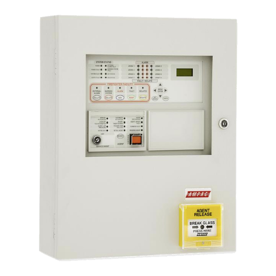
- Page 1 Fire detection and evacuation solutions that save lives. ZoneSense PLUS Agent Release Installation, Commissioning & Operation MAN1543-6...
- Page 2 MAN1543-6 Isolating a Zone 1. Indicator - Zone Alarm Indicator (flashing) - Common Alarm Indicator (flashing) - First Zone in Alarm is displayed on the LCD. Z7 ZONE SEVEN 2. To Isolate External Bell press 3. To Isolate Warning System press ...
- Page 3 MAN1543-6 Isolating a Zone Example below isolates Zone 2) AMPAC SU 00 : 15 Default Screen Moving to the ISOLATE MENU STATUS FAULTS Press press ISOLATES TEST Press press ZONE 1 ZONES ACTIVE ISOL'D ...
-
Page 4: Table Of Contents
MAN1543-6 Contents About This Manual ..........................6 Introduction ..........................6 General Requirements ........................6 References ........................... 6 Symbols ............................6 System Overview ..........................7 ZoneSense PLUS - AR Description ......................8 Placing the Basic System into Operation ....................10 Unpacking ...........................10 Anti-Static Precautions ........................10 Working On The System ......................10 The Cabinet ..........................10... - Page 5 MAN1543-6 Outputs – Volt Free Relay Non-Programmable................25 5.8.1 Fault Output (TB5 8 / 9 / 10) ....................25 Auxiliary Power Output (TB12 1 / 2).....................25 5.9.1 Reset Terminal / Buzzer Output. (TB12 / 3) ................26 5.9.2 Buzzer ..........................26 5.9.3 Internal Communications Connector (RS485) ...............27 Agent Release Control ........................28 Operation ............................28 Agent Release Module .........................31...
-
Page 6: About This Manual
MAN1543-6 1 About This Manual 1.1 Introduction This manual contains all the information required to install, commission and operate the ZoneSense PLUS - AR Fire Alarm Control Panel (FACP) and is only available to and for the use of personnel engaged in its installation, commissioning and operation. -
Page 7: System Overview
MAN1543-6 2 System Overview The ZoneSense PLUS - AR 4 and 8 zone FACP complies with the highest level of approval for any applicable code and can be connected to an appropriate Fire Service monitoring facility. As a Minimum, the conventional panel meets the following Standards; ➢... -
Page 8: Zonesense Plus - Ar Description
LCS’s come in indoor or outdoor versions. As part of a system solution, Ampac also offers other ancillary devices such as: ➢ Orbis conventional detectors, ➢ Warning signs, and ➢... - Page 9 MAN1543-6 Main and reserve agent release storage cylinders are supported. The circuit between the panel and the cylinders is monitored for short and open circuit. Connection from the AR panel to the LCS is via RS485 communications protocol. Subsequent LCS’s are connected in a ‘daisy chain’...
-
Page 10: Placing The Basic System Into Operation
MAN1543-6 4 Placing the Basic System into Operation 4.1 Unpacking Carefully unpack the ZoneSense PLUS-AR. The package should include: ➢ Main Card, with all controls and indicators mounted directly onto it; ➢ a switch-mode power supply; ➢ 2 X 12 Volt batteries connected in series. ➢... -
Page 11: Mounting The Cabinet
MAN1543-6 4.5 Mounting The Cabinet Note: It is recommended the cabinet should be installed in a clean, dry, vibration-free area. Open the front door. Use the keyhole mounting holes in the top corners and in the lower middle of the unit to mount it on the wall. -
Page 12: Power Supplies And Ac Mains Installation
MAN1543-6 4.7 Power Supplies and AC Mains Installation 4.7.1 Primary Power Supply The ZoneSense – AR Power Supply PCB combines the functions of; ➢ A mains to D.C. switched mode power supply unit that operates from a supply of; 204 - 264VAC @ 47 – 63Hz supplying the system while all zones are in alarm ➢... -
Page 13: Connecting The Mains Power To The Power Supply
MAN1543-6 4.7.5 Connecting the Mains Power to the Power Supply FERRITE CORE NEUTRAL (BLUE) EARTH (GREEN) ACTIVE (BROWN) (AC IN) MAINS CABLE COMBINED MAINS SWITCH & MAINS INDICATION F1: 2A Fuse PROTECTIVE PERSPEX COVER CHASSIS EARTH DANGER AC ON TERMINAL NOTE: MAINS CABLE SHOULD BE NO LESS THAN 0.75mm... -
Page 14: Battery Charger
MAN1543-6 4.8 Battery Charger The battery charger is an integral part of the Power Supply and is capable of ➢ Recharging standard sized system batteries within 24 hours ➢ Detecting a missing, damaged or undercharged battery ➢ Protecting the battery against reverse or a short circuit condition ➢... -
Page 15: Main Control Board
MAN1543-6 5 Main Control Board The Main Control Card and its front display panel combined with the Power Supply / Battery Charger and batteries form the basis for the ZoneSense PLUS - AR FACP. ASSEMBLED BRIDGE SHIELD BRIDGE DECAL Figure 5: Exploded view of the Control Panel M O N RELAY MON O/Ps 1 - 4... - Page 16 MAN1543-6 Note: When connecting to the Brigade PSU Monitor board transient and “Flyback” (Back EMF) protection methodologies MUST be applied. Cabling Connector Purpose /Pins Link pins & • when the front panel keyswitch is NOT used. LCD Driver CN3 &...
- Page 17 MAN1543-6 Ohms Warn Sys Bell Ohms Note: If a diode is NOT fitted internally to the Bell / Sounder a diode MUST be fitted as shown - fit 1N4004 or similar Figure 8: General Wiring Diagram ZoneSense PLUS...
-
Page 18: Earth Monitoring
MAN1543-6 5.1 Earth Monitoring The earth monitoring disable/enable feature is accessible via the SYSTEM menu at access level 3. Disabling the earth monitoring does not illuminate the Earth Fault LED on the control panel. Note: If ZoneSense PLUS - AR is connected to a third party system which has earth monitoring and it’s earth monitoring is being affected by ZoneSense PLUS - AR even after being disabled through programming the resistor R22 on the Main Card in ZoneSense PLUS - AR can be removed. -
Page 19: Inputs - Monitored (Tb3)
MAN1543-6 5.3 Inputs – Monitored (TB3) 5.3.1 Common Terminal (TB3 Com) The COM terminal is used as the common for the following three 0v potential inputs. 5.3.2 Door Switch Input (TB3 Com / 1) This optional input is used for connecting the FACP’s door switch. Connection is to TB3 COM & 1 5.3.3 MCP (TB3 Com / 2) The optional external MCP I/P is monitored for normal operation and must be mapped to a particular zone. -
Page 20: Detector Zones (Tb13 & Tb14)
MAN1543-6 5.4 Detector Zones (TB13 & TB14) Zone circuit connections are made directly to TB13 & TB14 on the Main Card and if screened cabling is used the screen is terminated at the panel's chassis earth terminal. All zones can be programmed to operate in one of the 5 different configuration modes each with a reset time in the order of >... - Page 21 MAN1543-6 Note: A maximum of 40 ZoneSense PLUS - AR compatible Optical / Heat and Ionisation Detectors or Manual Call Points can be fitted to each circuit and mixed in any order. Note: An End of Line EOL (Factory set default = 3K3) device must be connected across the terminals of the last device on each zone circuit to allow the circuit to be monitored.
-
Page 22: Outputs - Monitored (Tb4)
MAN1543-6 5.5 Outputs - Monitored (TB4) 5.5.1 Alarm Outputs The panel has 4 dedicated individually monitored outputs which are; ➢ rated at 500mA @ 24VDC nominal; ➢ protected against short circuits; ➢ Monitored for open and short circuit conditions even when an output is active. The monitoring operates on a reverse voltage principal and will indicate a fault within 60 seconds. -
Page 23: Warning System Output (Tb4 3 / 4)
MAN1543-6 5.5.3 Warning System Output (TB4 3 / 4) Switched 24VDC. Operated by an alarm from a non-isolated zone. The “Warning System Isolate” switch controls this output. When pushed the “Warning System” output is inhibited and the LED is illuminated. If pushed again the output is toggled back to the normal state. Re-activates the audible fault indication if the output is still in fault and left isolated for longer than 8 hours. -
Page 24: Conventional Sounder Circuit Wiring (Tb4)
MAN1543-6 5.5.6 Conventional Sounder Circuit Wiring (TB4) Each of the four alarm outputs can also be configured to drive a conventional sounder circuit. Ohms Ohms Ohms Ohms Sounder Sounder Sounder Sounder + Z7 - + Z8 - + 2 - + 4 - + 1 - + 3 -... -
Page 25: Outputs - Monitored Open Collector (Tb5)
MAN1543-6 5.6 Outputs – Monitored Open Collector (TB5) Definition: A monitored open collector output for user connections. Via the front panel it is possible to program which zones will operate any of the outputs. 5.6.1 Alarm Output (TB5 1 / 2) The output operates in parallel to the Alarm Output relay and energises if a zone is not isolated and is in the alarm condition. -
Page 26: Reset Terminal / Buzzer Output. (Tb12 / 3)
MAN1543-6 5.9.1 Reset Terminal / Buzzer Output. (TB12 / 3) An output rated at 24VDC @ 100mA that can be configured to the user’s requirement to provide either of the following 2 functions: Reset. Reset is used to reset field devices such as beam detectors that is Reset switches negative for a period of 1.2 seconds on operation of the “Reset”... -
Page 27: Internal Communications Connector (Rs485)
MAN1543-6 5.9.3 Internal Communications Connector (RS485) PCB mounted connectors provide serial communications to internal ancillary boards. CN9 on the Main Card cables to CN5 or 6 on the Agent Release Card or CN1 or 2 on the “Add on” front panel cards and CN5 on the Main Card cables to CN1 or 2 on the back pan boards Front Panel Front Panel... -
Page 28: Agent Release Control
MAN1543-6 6 Agent Release Control Agent Release control consists of an Agent Release Module, Termination Board and an optional Local Control Station. 6.1 Operation Introduction The Agent Release Module and Termination Board communicate with the FACP via the RS485 multi-drop bus. The Local Control Station communicates only with the Termination Board via a separate RS485 bus. - Page 29 MAN1543-6 Single Zone Activation, the following discharge sequence is executed; ➢ Automatic Activation LED is illuminated on the Agent Release Module and Local Control Station. ➢ Stage 1 outputs are switched to +24VDC. (FIRE ALARM sign illuminated, aural alarm sounds). ➢...
- Page 30 MAN1543-6 ➢ A Fault with a LCS. Note #1: The common fault indicator on the Agent Release Module and Local Control Station is illuminated for any Fault condition. Note #2: For a pressure switch fault, low pressure switch fault, lock-off valve fault, stage 1 output fault, stage 2 output fault and interlock fault, the FACP will signal the brigade.
-
Page 31: Agent Release Module
MAN1543-6 6.2 Agent Release Module The Agent Release Module controls and monitors all the requirements for agent release and carries the slide in label for identification of the agent and application area. Top Module & PCB TERMINATOR LINK Securing Clips ADDRESS Fit EOL Termination SWITCH... -
Page 32: Local Control Station (Lcs)
MAN1543-6 6.3 Local Control Station (LCS) The Local Control Station is supplied fitted into an IP40 rated enclosure and has the same indicators and Manual Release switch as the Agent Release Module within the Fire Alarm Control Panel (FACP) but no Agent Select button or Service Inhibit keyswitch. - Page 33 MAN1543-6 LCS Operation & Controls Lifting the cover and pressing the MCP starts the manual agent release sequence. This two action safety feature prevents any accidental operation of the control and should not be disabled. Agent Release / LCS Indicators There are 12 indicators on both the Agent Release Module and Local Control Station.
- Page 34 MAN1543-6 Note: The Interlock is a Monitored Input and can be defaulted to the ON position by terminating the input (TB2 7 & 8) into a 2K2 resistor. INITIAL AGENT (Yellow) Illuminated when the “Initial Agent” is selected. RESERVE AGENT (Yellow) Illuminated when the “Reserve Agent”...
-
Page 35: Agent Release Termination Board
MAN1543-6 6.4 Agent Release Termination Board INPUTS SYST. STAGE2 RELEASE LCS CABLE STAGE1 SIG+ + L.PSW- 0VDC MAIN RESV N/0 C O M + N/0 C O M SCRN SIG- +24VDC + PSW - + LOCK- + - Outputs are Monitored MONITORED FIRED INOP... -
Page 36: Interface Wiring
MAN1543-6 6.4.1 Interface Wiring Monitored Inputs TB2 1 & 2 Solenoid & Metron This input relies on N/O or N/C relay contacts used in conjunction with 22K EOL and 4K7 series resistors. The type of agent release mechanism and contacts used has to be set in the Programming Menu for the input to function as per the manufacturers specifications and be in accordance with the relevant Standard. -
Page 37: Warning Signs
MAN1543-6 6.4.2 Warning Signs Description The warning signs are driven by a 2 wire system and may be configured for single or dual stage operation. An on-board buzzer provides an audible warning which may be disabled by removing JP3. External evacuation devices, e.g. sounders may be connected to TB3 of the input termination board. An external mute push-button (N/O contacts) may also be connected to Term 3 on the warning sign PCB to enable the user to silence the internal buzzer and evacuation device. - Page 38 MAN1543-6 Configuration – Jumper Settings JP 1 (Continuous / Flashing) JP 2 (Single / Dual Stage) LED's Permanently Full sign on for Stage 1-2 Continuous 1-2 Single Stage 1&2 Flashing LED's flashing Dual Stage Half sign on for Stage 1 (DEFAULT) 1.5Hz (DEFAULT)
- Page 39 MAN1543-6 6. (+) POS TO NEXT WARNING SIGN IF 5. (+) POS MULTIPLE SIGNS ARE USED C OM+ FIT 10K EOL TO LAST 4. (-) ALERT SIGN ON CHAIN STG1 3. (-) ALERT STG2 2. (-) EVAC B R D 42W TB 2- A 1.
-
Page 40: Battery Capacity Calculation
MAN1543-6 7 Battery Capacity Calculation The standby power source capacity, or battery capacity, determines how long the system will continue to operate in the event of the loss of the primary power source. It therefore becomes necessary to calculate the battery and hence power supply / battery charger capacity required for each installation. -
Page 41: Power Supply & Battery Calculator
MAN1543-6 7.3 Power Supply & Battery Calculator Criteria Example Iq Calculation Iq Calculation Panel Configuration No Off X mA = Iq No Off X mA = Iq Basic 4 zone gas panel Basic 8 zone gas panel Interface Cards/Boards Sounder Board Brigade Board Input Board Fire Fan Module... -
Page 42: Primary Power Source Calculations
MAN1543-6 Criteria Example Battery capacity at end of ( Iq x 24 ) + ( Ia x 0.5 ) ( Iq x 24 ) + Fc( Ia x 0.5 ) battery life Note: the figure of 24 Fc – capacity de-rating factor. ... -
Page 43: Battery Guidelines
Note #2: Types are the Manufacturers and not the suppliers. Note #3: Those listed below in small Italic are not generally used by Ampac. Note #4: Automotive type batteries are not normally suitable for stationary use. afp - 791... -
Page 44: Trouble Shooting Chart
RS485 Communication Bus not working in the communication line Can not access a menu Incorrect Password entered Ring AMPAC and directions will be given to provide Forgotten Password you with a temporary code Make sure you have a 10K Ω EOL resistor fitted and... -
Page 45: Installation And Commissioning Report
MAN1543-6 10 Installation and Commissioning Report This ZoneSense PLUS - AR Fire Alarm Control Panel is installed at: Company Name Street Suburb State / Country (Company Name & Installation Address) Postcode Owner or Owners' Authorised Representative: Company Name Street Suburb State / Country (Company Name &... -
Page 46: Procedure
MAN1543-6 10.1 Procedure The following tests are the minimum that shall be performed when commissioning a system using the ZoneSense PLUS - AR Fire Alarm Control Panel. Supplements to these tests may be added by way of attachments or notation ) to this documentation. -
Page 47: System Information
MAN1543-6 10.2 System Information Tick relevant box Ensure that all detectors used in the system: Are listed in the operator's manual; Are compatible with the installed AZF, iii. Do not exceed the permitted number of detectors on each circuit; and ... - Page 48 MAN1543-6 For flame detectors, perform the following: Check that the number and type of detectors provide adequate protection of the area. Check that there are no 'blind' spots in areas protected. iii.
-
Page 49: Statement Of Installation Compliance
MAN1543-6 11 Statement of Installation Compliance Please PRINT Name of Building: Address: I/We have installed in the above building an alteration to the system manufactured by, OR a system manufactured by. (Name of Service Provider) The system is connected to monitoring service provider by a Permanent , Non-Permanent connection Date of connection... - Page 50 MAN1543-6 I/We Print Name/s Hereby certify that the installation has been thoroughly tested from each actuating device and that a test of the transmission of the alarm signal to the monitoring service provider has been satisfactorily carried out. I/We further certify that the whole system and all components called up in Clause 1.3 in connection therewith are installed entirely in accordance with the current requirements of AS 1670.l, - Except with regard to the following details which have already been approved, approval attached.
-
Page 51: Installation Details
MAN1543-6 12 Installation Details Indicate with a number in brackets the number of actuating devices in concealed spaces. Add addressable loop number in brackets where applicable. Number and Type of Actuating Devices Thermal Number Alarm Smoke Flame Manual Zone Call Other Actuating Ion Photo... -
Page 52: Certification Information
MAN1543-6 13 Certification Information The ZoneSense PLUS - AR is designed and manufactured by: AMPAC TECHNOLOGIES PTY LTD 7 Ledgar Rd Balcatta WA 6021 Western Australia HEAD OFFICE 61-8-9201 6100 FAX: 61-8-9201 6101 Manufactured to: Certificate of Compliance Number: Equipment Serial Number:... -
Page 53: Specifications
MAN1543-6 14 Specifications Mechanical Dimensions Metal Cabinet: (mm) 500H x 405W x 145D Note: A battery box is available should either model be optioned to capacity. Environmental Temperature: -5ºC to + 55ºC Humidity: 25% to 75% Non condensing Power Supply Input Voltage: 180 - 264VAC ( 47-63Hz ) Protection (Quick Acting Fuse):... -
Page 54: Glossary Of Terms
MAN1543-6 15 Glossary of Terms ACF: ANCILLARY CONTROL FACILITY ACKD: ACKNOWLEDGED AHU: AIR HANDLING UNIT ALM: ALARM AVF: ALARM VERIFICATION FACILITY AZF: ALARM ZONE FACILITY AZC: ALARM ZONE CIRCUIT RELAY COMMON CONTACT (WIPER) CIC: CONTROLLER INTERFACE CARD CONNECTOR CPU: COMMON PROCESSOR UNIT DGP: DATA GATHERING POINT EARTH: BUILDING EARTH... -
Page 55: Definitions
MAN1543-6 16 Definitions Addressable system - a fire alarm and detection system that contains addressable alarm zone facilities or addressable control devices. Alarm Verification Facility (AVF) - that part of the FACP, which provides an automatic resetting function for spurious alarm signals so that they will not inadvertently initiate Master Alarm Facility (MAF), or ACF functions. -
Page 56: Quick Reference Guides
MAN1543-6 17 Quick Reference Guides FAULTS STATUS MENU MENU ENTER ENTER MENU FAULTS F 1 / 2 F 2 / 2 SOFTWARE MENU OUTPUTS VOLTAGE ENTER 2 Flt/s ENTER FIRE FAN FIRE CTRL VER E1.2 MENU MENU CANCEL MENU MENU ENTER ENTER ENTER... - Page 57 MAN1543-6 ENTER MENU SYSTEM PASSWORD ENTER FACTORY DEFAULT MENU PASSWORD IS 3333 ENTER MENU ALARM RESOUND EXAMPLE OF BUZZER ENTER YES / NO YES / NO ENTERING PASSWORD 3333 EXAMPLE MENU ENTER SET RESOUND TO YES THEN MOVE TO ALARM EARTH MON PASSWORD Y E S...
- Page 58 MAN1543-6 Agent Notes: If only one trigger zone is allocated a zone then the system will be activated by one zone only. Any trigger zone may be allocated to any zone. However when a trigger zone has been allocated eg T1 to zone 1 then only the remaining trigger zones T2, T3 or T4 are each available to be PROGRAM allocated one of the remaining detector zones.
-
Page 59: Front Panel Configuration Labelling
MAN1543-6 18 Front Panel Configuration Labelling SOUNDER SOUNDER SOUNDER SOUNDER SOUNDER SOUNDER SOUNDER SOUNDER WARN ZONE CONFIGURATION BELL ALARM B ALARM 1 B ALARM 2 RELAY 1 RELAY 2 RELAY 3 RELAY 4 RELAY 5 RELAY 6 RELAY 7 RELAY 8 FAN 1 FAN 2 FAN 3... - Page 60 MAN1543-6...
- Page 61 MAN1543-6 UNCONTROLLED DOCUMENT NOTE: Due to AMPAC’s commitment to continuous improvement specifications may change without notice.
Need help?
Do you have a question about the ZoneSense PLUS Agent Release and is the answer not in the manual?
Questions and answers