Table of Contents

Related Manuals for StarTech.com SV1110IPEXT


Summary of Contents for StarTech.com SV1110IPEXT
- Page 1 SERVER REMOTE CONTROL Secure KVM-over-IP with Integrated Web Interface and Virtual Drive Technology SV1110IPEXT Instruction Guide * Actual product may vary from photo The Professionals’ Source For Hard-to-Find Computer Parts...
- Page 2 StarTech.com is now offering the IPMI and modem software upgrades on the SV1110IPEXT as a standard feature. If you are unsure whether your unit has these features enabled, you can verify what options are installed using these instructions: 1) Login to the SV1110IPEXT Web interface as Admin.
-
Page 3: Table Of Contents
To use the optional dedicated WAN port Configuration via serial port To use USB connections on host and/or virtual disk emulation To install the SV1110IPEXT into a rack or cabinet To add a redundant power supply INSTALLING THE SV1110IPEXT Connecting the KVM to the Host Computer and Network... - Page 4 SV1110IPEXT Instruction Guide USING THE VNC MENU Welcome Window Bribar Feature Main Menu VirtKeys Menu Video Tuning Menu Disk Control Menu GETTING PEAK PERFORMANCE TROUBLESHOOTING SPECIFICATIONS SUPPORTED PROTOCOLS SUPPORT AND WARRANTY INFORMATION REGULATORY COMPLIANCE STATEMENTS APPENDIX A: ABOUT SECURITY CERTIFICATE WARNINGS...
-
Page 5: Introduction
1 x Instruction Guide Required Cables and Hardware The included integrated KVM cable will allow you to connect the SV1110IPEXT to most IBM compatible computers. Depending on your requirements and how you wish to handle the initial configuration of the unit, you may wish to use the following additional cables and hardware. -
Page 6: To Use The Optional Dedicated Wan Port
To use USB connections on host and/or virtual disk emulation • 1 x USB Type A to 5-pin mini-B cable StarTech.com part number: USB2HABM3 To install the SV1110IPEXT into a rack or cabinet • 1 x Rack kit (supports up to two units) StarTech.com part number: 1110EXTRACK... -
Page 7: Installing The Sv1110Ipext
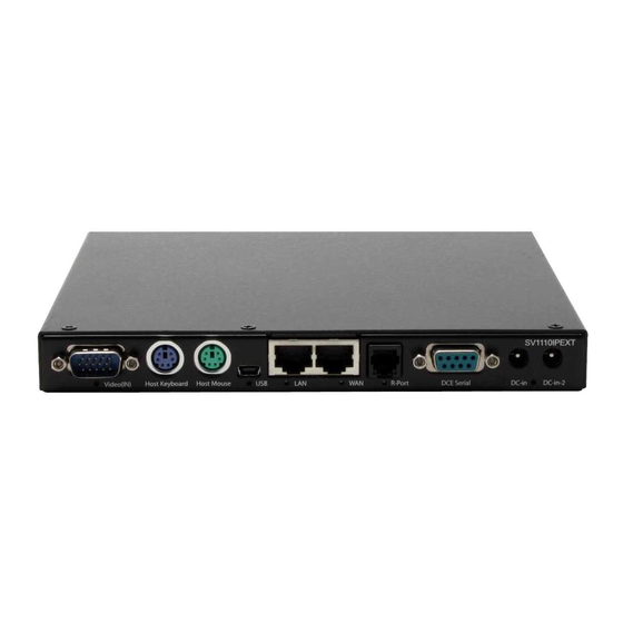
SV1110IPEXT Instruction Guide Installing the SV1110IPEXT Rear Panel Video (IN) Host Host R-Port DCE Serial DC-in DC-in-2 Keyboard Mouse... -
Page 8: Connecting The Kvm To The Host Computer And Network
SV1110IPEXT as appropriate. 6. Using a Category 5 Ethernet patch cable, connect the LAN connector on the rear panel of the SV1110IPEXT to a network data jack (usually on a hub, switch, router, or pre-wired wall jack). - Page 9 USB port on the managed computer. 7. Using a Category 5 Ethernet patch cable, connect the LAN connector on the rear panel of the SV1110IPEXT to a network data jack (usually on a hub, switch, router, or pre-wired wall jack).
-
Page 10: Connecting A Local Keyboard, Mouse, And Monitor
Video (Out) (Power/R-Port/WAN Link/LAN Link/USB/Video) Keyboard Mouse There are a number of lights (LEDs) on the front and rear panels of the SV1110IPEXT: • Power: Indicates one or both of the DC power inputs is providing your system with power. -
Page 11: Disabling Mouse Acceleration On The Host Computer
0/0 0 Configuration Methods Explained The SV1110IPEXT offers three distinct methods for configuring the unit for your network. The method that will work best for you will depend on your level of experience and your specific network configuration. -
Page 12: Web Configuration Using Static Ip
MAC Address: 00-0E-C5-00-08-1A Device Name: (none) The easiest way to identify your SV1110IPEXT on the network is by its MAC address, a unique hardware identifier that is specific to your unit. The MAC address of the unit can be found on a white sticker on the bottom of the SV1110IPEXT. Write down this number and keep it for future reference. -
Page 13: Terminal Configuration Using A Serial Cable
IP address 192.168.1.123 to access the Web configuration system. Terminal Configuration Using a Serial Cable Configuring the SV1110IPEXT using a serial cable is the best choice if you need to pre- configure the unit before attaching it to a network, i.e. when sending to a branch office, customer site, etc. - Page 14 Connect a female end of a serial cable to the serial port that will be used for serial access on the host computer. Connect the opposite end (male if connecting to the DCE Serial port, female if connecting to the DTE Serial port) to the SV1110IPEXT. Configure the terminal software with “8N1” settings: Connection speed: 115200 bps No.
-
Page 15: Configuring The Sv1110Ipext
Configuring the SV1110IPEXT Using the Web Interface The Web interface is the most intuitive way to configure the SV1110IPEXT. It also offers a Java-based VNC client that you can use to control the host computer from a remote location. The SV1110IPEXT supports any industry-standard HTML Web browser. - Page 16 The Admin/Setup Screen This is the menu that will allow you to access all the features you will need to perform an initial configuration of the SV1110IPEXT. Each of the options is explained in detail here. Network Configuration (IP address. Netmask, etc) Dynamic Host Configuration Protocol (DHCP) Automatic network configuration using DHCP is: Enabled/Disabled.
- Page 17 SV1110IPEXT Instruction Guide you greater control over how the SV1110IPEXT is configured for access from outside the local network, particularly if a firewall or proxy is in use. Domain Name Server (optional) This section allows you to specify DNS servers and the default DNS domain suffix in use on the network.
- Page 18 SV1110IPEXT Instruction Guide Record changes. If the user already exists, you will change the password for that user. Change system identification Provides details about this SV1110IPEXT that will be available to DHCP servers, SNMP agents, and VNC clients. While these values do not affect the operation of the unit, they make it easier to manage on the network.
- Page 19 SV1110IPEXT Instruction Guide Takes you to the Status menu (see below). SNMP agent setup and configuration This menu allows you to configure the SV1110IPEXT so it can be recognized and managed using industry-standard Simple Network Management Protocol software. RADIUS authentication setup...
- Page 20 Auto Self Upgrade The SV1110IPEXT module includes an innovative feature allowing the unit to upgrade itself over the Internet. Simply click on the button labeled Upgrade to Latest and the module will go out to the Internet and download the latest version of the system firmware and then install it.
- Page 21 SV1110IPEXT Instruction Guide NOTE: Remember the following during the firmware upgrade… • Do NOT turn off power to unit before this operation completes successfully. It may take several minutes to write to flash memory. • The unit will sometimes reboot as part of the upgrade procedure, depending on which system component is upgraded.
- Page 22 When emulating a floppy disk or RAM disk, the data is stored in RAM on the SV1110IPEXT itself. In order to emulate a CD-ROM disk drive, a web server is required to provide the CD-ROM image data. The web server must be accessible to the module, which communicates with it constantly as data is needed.
- Page 23 8MB. CD-ROM Mode The SV1110IPEXT does not store any data in this mode. Instead, it emulates a USB CD- ROM drive with a disk inserted. The data from that disk must be provided by an external web server.
- Page 24 SV1110IPEXT Instruction Guide a working, bootable CD-ROM. To create a bootable floppy, you can format the emulated floppy from the target system, or read the data from a working boot floppy. This can be done from Windows using “Disk Copy” (right click on the drive letter in the Windows Explorer) or by using a program like “RAWRITE”.
-
Page 25: Using The Terminal Interface Via Serial Port
Note that you must use the W option to confirm and apply any changes you made before you exit the terminal session. If you changed the status of the Ethernet Bridging feature, you will also need to power the SV1110IPEXT on and off again to enable your changes. -
Page 26: Accessing The Vnc Interface
SV1110IPEXT Instruction Guide ----------------------------------- Server Remote Control Network Setup ----------------------------------- NOTE: This interface is used to set network parameters and perform certain recovery procedures, but the majority of setup and configuration can only be done using the web interface. Primary Ethernet Port (LAN) (00:0e:c5:00:08:1a) DHCP is enabled. -
Page 27: Web Interface
SV1110IPEXT Instruction Guide • Native VNC client: There are several third-party software programs that use the standard VNC protocol, available in open source and commercial VNC clients. • SSH access: By default, there is a standard SSH server running on port 22 (the standard SSH port). -
Page 28: Ssh Tunnel (With Native Vnc Client)
SV1110IPEXT Instruction Guide The best client currently is TightVNC (www.tightvnc.com). Binaries are available for Windows, Linux, MacOS and many versions of Unix. Source code for all clients is available there too. This version of VNC is being actively developed. The authoritative version of VNC is available from RealVNC (www.realvnc.com). -
Page 29: Welcome Window
SV1110IPEXT Instruction Guide allow you to control the many features of the SV1110IPEXT without using the web interface or a custom client. Welcome Window When you initially connect to the system, a window similar to this one will be shown. - Page 30 SV1110IPEXT Instruction Guide USB: Resets the USB connection by simulating an unplug and replug. Forces operating system to recognize the USB keyboard, mouse and emulated disk drive. ÷4, ÷8: Switches to thumbnail mode, at indicated size. Ctrl-Alt-Del: Sends this key sequence to the host. Works immediately.
-
Page 31: Main Menu
SV1110IPEXT Instruction Guide Main Menu To access the main menu, press F7 twice quickly. You must press the key twice within one second. If you press it once or too slowly, then the F7 key(s) are sent to the host, just like any other key. -
Page 32: Virtkeys Menu
KVM Menu: Generates the key sequence used to access the on-screen menu for a enterprise-class KVM switch. When these conventional KVM switches are combined with the SV1110IPEXT, this key makes accessing their built-in menu easier, especially from the Java client. This button will only be shown when an external KVM has been enabled via the web interface. -
Page 33: Video Tuning Menu
SV1110IPEXT Instruction Guide Meta key at the same time. Alternatively, you may move the mouse outside this window, press the regular key, and then choose -RESET- to release all depressed keys. The VirtKeys menu can be left open while using the host system. You can then click the required button at the suitable time, and still interact with the host in a normal fashion. -
Page 34: Disk Control Menu
SV1110IPEXT Instruction Guide cropping or any other changes to that image. Press the Auto button and the system will calibrate color for the best possible picture in approximately one minute. If the system cannot find the test pattern on the screen, it will say so. Check that the pattern isn't scaled or covered up. -
Page 35: Getting Peak Performance
Network performance • The SV1110IPEXT will always send as much data as it can, given what's happening on the screen and the actual network performance. When nothing is changing on the video screen, zero bytes are sent over the network. If the whole screen is changing, then the module will send as much data as your network connection and VNC client can handle while not allowing it to fall behind. -
Page 36: Troubleshooting
SV1110IPEXT Instruction Guide Troubleshooting Forgotten master password. You can reset the master password using the serial interface on the module. Use the `S' command, and type a new password. The old password is not required for this procedure. Remote mouse and local mouse don't line up. -
Page 37: Specifications
SV1110IPEXT Instruction Guide Don't set LAN and WAN to the same IP Address. This type of installation will not work. If you want to use both ports in redundant mode, enable the Ethernet bridging option and plug both into the same network. The WAN IP address is not used in that configuration. -
Page 38: Supported Protocols
SV1110IPEXT Instruction Guide Supported Protocols Service Description Benefits Secure Shell May be used to securely “tunnel” VNC and HTTP protocols. HTTP Web redirector (to HTTPS) Convenience server to redirect all web traffic to encrypted port. Clear-text HTTP is not supported. -
Page 39: Regulatory Compliance Statements
We are constantly adding new information to the Tech Support section of our web site. To access this page, click the Tech Support link on our homepage, www.startech.com. In the tech support section there are a number of options that can provide assistance with this product. -
Page 40: Appendix A: About Security Certificate Warnings
(CAs) and contain essential details about a site that must match the information supplied to your Web browser. Why do I receive a warning when I access the login screen on the SV1110IPEXT? As it redirects you to a secure (SSL) session by default, the login screen may generate a warning from your Web browser or the VNC Java client for two different reasons. -
Page 41: Appendix B: Using The Advanced Video Tuning Feature
VNC sessions, and can be access by clicking the Advanced button on the Video Tuning VNC menu. While many users will probably allow the SV1110IPEXT to automatically configure the video properties, you can use this menu to exercise a great deal of control over the settings if you wish. - Page 42 SV1110IPEXT Instruction Guide When making small changes to the video parameters, sometimes these changes are not reflected in the displayed screen immediately, particularly if the noise filter is enabled. Press this button to see the immediate effect of the changes.
-
Page 43: Appendix C: The Ipmi Upgrade Option
If the Host Computer Does Not Support IPMI If the host computer you are managing with the SV1110IPEXT does not support IPMI, StarTech.com offers a non-IPMI solution that also works via serial port and acts as a power concentrator and a power management device: the 8 Outlet Serial Power Console and Switch (PM815NAS). - Page 44 Activating the IPMI Option A system without the IPMI option enabled The SV1110IPEXT contains the necessary software to use IPMI. To enable this capability, you must purchase the software option from StarTech.com unless you have purchased a model with the feature pre-enabled. To verify whether the IPMI feature is enabled on your unit, login to the Web interface as Admin, click the Setup/Admin button at the top of the page, and click Firmware and flash memory management.
- Page 45 Front Panel (DTE Serial Port) Rear Panel (DCE Serial Port) You can use either serial port on the SV1110IPEXT to send IPMI access; your choice will dictate the type of cable you will use to make the connection. The DTE Serial port on the front panel requires the use of a null modem serial cable.
- Page 46 VNC sessions to fail and you will need to re-establish them. Accessing the Status Screen The SV1110IPEXT allows you to monitor the status of the host computer via IPMI using either the Web interface or the VNC client. The information you will be able to view...
- Page 47 SV1110IPEXT Instruction Guide using the status screen will depend on the model of host computer being managed. Since IPMI implementations vary widely across manufacturers, the information you are able to see on your status screen may differ from the examples. Note that the Status screen will not allow you to make any configuration changes and is for monitoring purposes only.
- Page 48 SV1110IPEXT Instruction Guide Controls on the Home Screen (Web) Once IPMI is enabled and functioning correctly, a set of controls will appear immediately under the thumbnail image of the host computer on the Home screen on the Web interface. Note that you must be logged in as admin to use this feature. From here, you have four options: Hard Reset: Equivalent to pressing the RESET button on the managed computer.
- Page 49 SV1110IPEXT Instruction Guide Reset: Equivalent to pressing the RESET button on the managed computer. (The computer will restart.) ON/OFF: Powers the host computer on or off depending on the current state of the host computer; equivalent to pressing the POWER button on the host computer.
-
Page 50: Appendix D: The Modem Option Upgrade
Appendix D: The Modem Option Upgrade Background The modem option allows the SV1110IPEXT to act as an Internet connection server for increased security and flexibility in connecting with the host computer. Unlike the TCP/IP connection used with the standard Web configuration and VNC clients, the... - Page 51 “downstream” rate is often within a similar range for a typical connection. Therefore, speeds below 56,000 bps do not indicate a problem with the modem or the SV1110IPEXT but simply reflect the line conditions at the time the connection is made. Front Panel (DTE Serial Port)
- Page 52 The DCE Serial port on the rear panel is used to connect the modem to the SV1110IPEXT and requires the use of a straight through serial cable. Place the modem near the SV1110IPEXT and an available telephone jack. Connect the modem to the telephone jack, data cable, and power source according to the instructions in its documentation.
- Page 53 The init string is the command (using the standardized Hayes AT command set) that the SV1110IPEXT will send to the modem to activate it. The string included should work with the majority of modems and configures the following connection properties: answer incoming calls on the first ring, enable hardware flow control, and lock the connection speed.
- Page 54 14. You may select to add a shortcut to the desktop for this connection. Click Finish. You can now use this connection to access the SV1110IPEXT modem. Since you will still login to the unit through the Web interface after establishing a dial-up connection, the user name on the PPP connection and the user name used to access the Web interface do not have to be the same.
- Page 55 (see immediately above for instructions on what type of cable to use for the port you are accessing on the SV1110IPEXT) and begin a terminal session following the instructions under “Terminal Configuration Using a Serial Cable” in this manual. Once...
- Page 56 Modem init chat script failed The modem did not respond to the initialization string from the SV1110IPEXT. You may need to change the init string or verify the cabling and modem status.
-
Page 57: Appendix E: Using Optional R-Port Devices
For the first serial device, connect the cable (provided) to the R-Port on the rear panel of the SV1110IPEXT. Connect the opposite end to the DATA OUT (or similar) port on the serial device. Note that some devices may use an integrated cable, so you will not need to make a separate connection on the serial device. - Page 58 Port devices. Advanced Configuration Using the Integrated SSH Shell In most cases, configuring the SV1110IPEXT to the same settings as the R-Port devices you are connecting should allow the devices to work with a minimum amount of configuration. However, you can also change the default settings on each R-Port device to fit your preferences and the needs of your application.
- Page 59 LED on the rear panel indicates that you have one of these units.) • Hardware handshaking (CTS/RTS) is required for speeds exceeding 9600 bps. It is enabled by default on the SV1110IPEXT, but may need to be enabled on...
- Page 60 SV1110IPEXT Instruction Guide the other end of the connection. For Unix systems, the command is: stty –crtscts < /dev/[serial port] • R-Port devices use a simple RS-485 multidrop network running at 115,200 bps. It is possible that every R-Port device will not be inputting/outputting data at the same rate at all time.
Need help?
Do you have a question about the SV1110IPEXT and is the answer not in the manual?
Questions and answers