
Subscribe to Our Youtube Channel
Related Manuals for HAMPTON BAY Palm Beach II


Summary of Contents for HAMPTON BAY Palm Beach II
-
Page 1: Ceiling Fan
191 410 Palm Beach II Ceiling Fan Owner’s Manual Palm Beach II Ventilador de Techo de 1,22 Manual del Propietario... -
Page 2: Table Of Contents
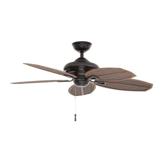
48” Palm Beach II Thank you for purchasing this Hampton Bay ceiling fan. This product has been manufactured with the highest standards of safety and quality. The finish Ceiling Fan by Hampton Bay of this fan is weather resistant, but over time will naturally weather and fade. -
Page 3: Safety Rules 1
READ AND SAVE THESE INSTRUCTIONS Do not use water or detergents when cleaning the fan or fan To reduce the risk of electric shock, insure electricity blades. A dry dust cloth or lightly dampened cloth will be has been turned off at the circuit breaker or fuse box suitable for most cleaning. -
Page 4: Unpacking Your Fan
Unpack your fan and check the contents. You should have the following items: Electrical Hardware 1. Slide-On Mounting Plate (inside canopy) 6. Blade Bracket (Flange) Set (5) (1 hanger pin, 1 locking pin, 1 rubber with blade bracket screws pre-installed 2. -
Page 5: Tools Required
Figure 2 installation hanger bar as shown in Figure 4 FIXTURES MAY NOT BE ACCEPTABLE FOR FAN (available at your Hampton Bay retailer). SUPPORT AND MAY NEED TO BE REPLACED. CONSULT A LICENSED ELECTRICIAN IF IN Installing Your Fan 3. -
Page 6: Hanging The Fan
Hanging the Fan Turn Canopy Ring to Remove Mounting REMEMBER Screws turn pow- (Supplied with er. Follow the steps below to hang your UL Listed Outlet Box) Outlet Box fan properly. Hook NOTE: This ceiling fan is supplied with two types of hanging assemblies;... -
Page 7: Close-To-Ceiling" Mounting
“Close-to-Ceiling” Mounting 4. Loosen, but do not remove, the set 6. Align the mounting holes with the holes screw on the collar on the top of the in the motor and fasten, using the three 1. Remove the canopy ring from the canopy motor housing. - Page 8 hook provided by utilizing one of the Follow the steps below to connect the fan holes at the outer rim of the ceiling canopy to your household wiring. Use the wire WHEN USING THE STANDARD BALL/DOWN- (Figure 12). If using standard mounting, seat connecting nuts supplied with your fan.
- Page 9 Finishing the Fan 5. Turn the wire connecting nuts upward and push the wiring into the outlet box. Installation STANDARD CEILING MOUNTING TO REDUCE THE RISK OF FIRE OR ELECTRIC SHOCK, DO NOT USE A WALL MOUNTED SOLID STATE SPEED CONTROL WITH THIS FAN. IT WHEN USING THE STANDARD BALL/DOWNROD WILL PERMANENTLY DAMAGE THE ELEC- MOUNTING, THE TAB IN THE RING AT THE BOT-...
- Page 10 slots and turn clockwise to lock in place. Im- Blade mediately tighten the two mounting screws REMOVE RUBBER STOPPERS ON THE BLACK firmly. PLATE BELOW THE MOTOR TO ATTACH BLADE ASSEMBLY TO MOTOR. REPLACE RUBBER Screws STOPPERS TO PREVENT WATER FROM ENTER- LOCKING SLOTS OF CEILING CANOPY ARE ING SWITCH HOUSING AND TO REDUCE RISK PROVIDED ONLY AS AN AID TO MOUNTING.
-
Page 11: Operating Your Fan 9
Blade Balancing TO REDUCE THE RISK OF PERSONAL INJURY, All blades are grouped by weight. Because nat- DO NOT BEND THE BLADE HOLDERS WHILE ural woods vary in density, the fan may wobble INSTALLING, BALANCING THE BLADES, OR even though the blades are weight matched. The CLEANING THE FAN. -
Page 12: Care Of Your Fan
Troubleshooting Care of Your Fan Here are some suggestions to help you Problem Solution maintain your fan. Fan will not start Check main and branch circuit fuses or breakers 1. Because of the fan’s natural movement, Check line wire connections to the fan and switch wire connections in some connections may become loose. -
Page 13: Specifications 11
GROSS FAN SIZE SPEED VOLTS AMPS WATTS CUBE FEET WEIGHT WEIGHT 0.25 13.1 1510 18.5 21.1 48” 0.37 29.9 2488 High 0.55 65.9 3902 These are approximate measures. They do not include Amps and Wattage used by the light kit. Distributed by Home Depot U.S.A., Inc. -
Page 14: Warranty Information
You must present a copy of the original Hampton Bay also warrants that all other fan parts, excluding any glass or acrylic blades, to be free purchase receipt to obtain warranty service. - Page 15 Palm Beach II de 1,22 m Gracias por comprar este ventilador de techo de Hampton Bay. Este producto se ha fabricado con las normas de seguridad y calidad más altas. El acabado Ventilador de Techo de Hampton Bay de este ventilador es resistente a la intemperie, pero con el tiempo, exhibirá...
-
Page 16: Normas De Seguridad
LEE Y GUARDA ESTAS INSTRUCCIONES cuidado al trabajar cerca del ventilador o al limpiarlo. Para disminuir el riesgo de descarga eléctrica, asegúrate de que la electricidad ha sido apagada en el cortacircuitos o la No usar agua o detergentes para limpiar el ventilador o las caja de fusibles antes de comenzar la instalación. -
Page 17: Cómo Desempacar El Ventilador 2
Desempaca tu Ventilador y Revisa el Contenido. Deberá incluir las siguientes piezas: Herrajes Eléctricos (1 pasador de 1. Placa de Montaje Deslizante (dentro de la 5. Ensamblaje del Motor del Ventilador / Caja soporte, 1 pasador de cierre, 1 junta de cubierta) del Interruptor goma para montaje cerca del techo) -
Page 18: Cómo Instalar El Ventilador
TAL VEZ DEBAN REEMPLAZARSE. EN CASO como se muestra en la Figura 4 (disponible en DE DUDA, CONSULTA A UN ELECTRICISTA CON la tienda minorista local donde se venden los LICENCIA. 3. Cómo Instalar el Ventilador productos de Hampton Bay). - Page 19 Cómo Colgar el Ventilador 4. Afloja, sin quitarlo, el tornillo en el Gira el Aro de la Cubierta para Quitarlo collarín ubicado en la parte superior de la RECUERDA desconectar corriente. carcasa del motor. Sigue estos pasos para colgar correctamente tu ventilador.
- Page 20 Montaje “Cerca del Techo” 5. Alinea los orificios en la parte inferior del orificios del motor y asegura con los tres tubo bajante con los orificios en el collarín tornillos y arandelas de seguridad retiradas 1. Retira el aro en la cubierta, girando a la ubicado en la parte superior de la carcasa en el paso 4 (Figura 11).
- Page 21 en el borde exterior de la cubierta de techo Sigue estos pasos para conectar tu ventilador (Figura 12). Si usas el montaje estándar, a tu circuito doméstico. Usa las tuercas CUANDO USES EL MONTAJE DE TUBO BAJANTE asienta la bola de soporte en el casquillo de conexión de cables que vienen con tu Y BOLA ESTÁNDAR, LA PESTAÑA EN EL ARO EN de la placa de montaje.
- Page 22 Finalizar la Instalación 3. Conecta el cable neutro (blanco) del ventilador al cable neutro blanco del circuito CIRCUITO DE SUMINISTRO del Ventilador eléctrico de la casa. 4. Después de conectar los cables, sepáralos MONTAJE DE TECHO ESTÁNDAR de manera que los cables verde y blanco queden de un lado de la caja eléctrica y el Caja cable negro del otro.
- Page 23 IMPORTANTE tornillos en la placa de montaje. Alza para Aspa enganchar las ranuras y gira de izquierda a RETIRA LOS TOPES DE GOMA SOBRE LA derecha para asegurar en su sitio. Ajusta con PLACA NEGRA DEBAJO DEL MOTOR PARA firmeza los dos tornillos de montaje. INSTALAR LAS ASPAS AL MOTOR.
-
Page 24: Cómo Operar El Ventilador
Balancear las aspas Clima cálido - (Hacia adelante) Un flujo de aire desviaciones de la medición deben estar hacia abajo crea un efecto refrescante como se dentro de 1/8”. Enciende el ventilador por muestra en la Figura 18. Esto te permite fijar 10 minutos. -
Page 25: Cuidado Del Ventilador
Solución de Problemas Cuidado del Ventilador Aquí tienes algunas sugerencias para el Problema Solución mantenimiento de tu ventilador. El ventilador no Revisa los fusibles o disyuntores principales y secundarios. 1. Debido al movimiento natural del ventilador, enciende Verifica las conexiones de los cables en lea al ventilador y las conexiones algunas conexiones pueden aflojarse. -
Page 26: Especificaciones
PIES PESO PESO PIES TAMAÑO DEL VOLTIOS AMPERIOS VATIOS CÚB. X VELOCIDAD NETO BRUTO CÚB. VENTILADOR MIN. Baja 0.25 13.1 1510 18.5 21.1 48” Media 0.37 29.9 2488 Alta 0.55 65.9 3902 Estas medidas son aproximadas. No incluyen ni el amperaje ni el vataje consumido por el kit de luces. Distribuido por Home Depot U.S.A., Inc. -
Page 27: Información De La Garantía 12
Usted debe presentar una copia del fábrica. Hampton Bay también garantiza por un período de un año, a partir de la fecha de compra por recibo de compra original para obtener garantía el comprador original, que todas las demás piezas del ventilador, sin incluir ninguna aspa de vidrio...
Need help?
Do you have a question about the Palm Beach II and is the answer not in the manual?
Questions and answers