Table of Contents
Advertisement
Quick Links
Item #
Model # PT13-13D-1
B
USE AND CARE GUIDE
VENTILATION FAN
READ AND SAVE T HESE INSTRUCTIONS
Questions, problems, missing parts? Before returning to the store,
call Hampton Bay Customer Service
8 a.m. - 7 p.m., EST, Monday-Friday, 9 a.m. - 6 p.m., EST Saturday
1-855-HD-HAMPTON
HAMPTONBAY.COM
THANK YOU
We appreciate the trust and confidence you have placed in Hampton Bay through the purchase of this ventilating bath fan. We strive to
continually create quality products designed to enhance your home. Visit us online to see our full line of products available for your home improvement needs.
Thank you for choosing Hampton Bay!
1
Advertisement
Table of Contents

Subscribe to Our Youtube Channel
Related Manuals for HAMPTON BAY PT13-13D-1


Summary of Contents for HAMPTON BAY PT13-13D-1
- Page 1 THANK YOU We appreciate the trust and confidence you have placed in Hampton Bay through the purchase of this ventilating bath fan. We strive to continually create quality products designed to enhance your home. Visit us online to see our full line of products available for your home improvement needs.
-
Page 2: Table Of Contents
Table of Contents Table of Contents ............2 Pre-installation..............4 Safety Information ............2 Planning Installation ..............4 Product Specifications ........... 3 Tools Required ................ 4 Typical Installation ............3 Hardware Included ..............5 Wiring Diagram ............... 3 Package Contents ..............5 Installation - New Construction ........ -
Page 3: Product Specifications
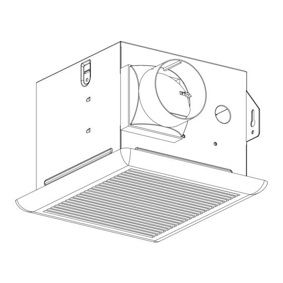
Product Specification SPECIFICATIONS SPECIFICATIONS Airfow: 70 CFM Power consumption: 22.8 W 120 V, 60 Hz Weight: 5.98 lbs. Duct diameter: 3 in. Ceiling Opening Dimension Requirements: 7-1/2 in. (L) x 7-1/4 in. (W) x 6 in. (H) Sound output: 2.0 Sone Typical Installation The ducting from this fan to the outside of the building has a strong effect on the air flow, noise and... -
Page 4: Warranty
Warranty LIMITED LIFETIME WARRANTY WHAT IS COVERED If this product fails due to a defect in materials or workmanship at any time during the frst year of ownership, the manufacturer will replace it free of charge, postage-paid at their option. This warranty does not cover products that have been abused, altered, damaged, misused, cut or worn. This warranty does not cover use in commercial applications. -
Page 5: Hardware Included
Pre-installation (continued) PACKAGE CONTENTS Part Description Quantity Fan Body Grille Duct connector HAMPTONBAY.COM Please contact 1-855-HD-HAMPTON for further assistance. -
Page 6: Installation - New Construction
Installation - New Construction CAUTION: Make sure power is switched off at service panel before starting installation. NOTE: Unit can be mounted in a ceiling or wall. Fan housing placement Joist or wall stud Place the fan housing next to a ceiling joist or wall stud. The ... - Page 7 Installation - New Construction (continued) 3 in. duct Install the duct Install a circular 3 in. duct (not included) and secure it with duct tape or clamps (neither included). Finish ceiling work. The ceiling hole should be aligned with the edge of the fan housing.
-
Page 8: Installation - Existing Construction
Installation - Existing Construction CAUTION: Turn off electricity at breaker box before beginning installation. Review all safety precautions. Remove the existing fan Remove the old fan from the ceiling. Measure the ceiling opening Measure the opening to assure it is large enough to accom- modate the new fan body (A) (7.50 in. - Page 9 Installation - Existing Construction (continued) Joist or Fan housing placement wall stud Place the fan housing next to a ceiling joist or wall stud. The fan housing should be level and perpendicular to the joist or stud. Joist or Mount the fan housing wall stud Mount the fan housing to the joist using long wood screw(AA)
-
Page 10: Care And Maintenance
Installation - Existing Construction (continued) Install the grille Pinch the mounting springs on the grille (B) and insert them into the narrow rectangular slots inside the fan. Push the grille (B) up toward the ceiling. Turn on electricity at the breaker box after finishing installation. Care and Maintenance WARNING: Disconnect power supply before servicing. - Page 11 Questions, problems, missing parts? Before returning to the store, call Hampton Bay Customer Service 8 a.m. - 7 p.m., EST, Monday-Friday, 9 a.m. - 6 p.m., EST, Saturday 1-855-HD-HAMPTON HAMPTONBAY.COM Retain this manual for future use.
Need help?
Do you have a question about the PT13-13D-1 and is the answer not in the manual?
Questions and answers