
Related Manuals for HAMPTON BAY 178 128


Summary of Contents for HAMPTON BAY 178 128
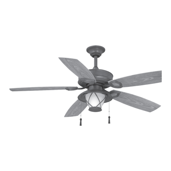
- Page 1 178 128 Glacier Bay Ceiling Fan Owner’s Manual Glacier Bay Ventilador de Techo de 1,32 Manual del Propietario...
- Page 2 Glacier Bay by Hampton Bay ®...
-
Page 3: Table Of Contents
Thank you for purchasing our ceiling fan. This product has been manufactured with the highest standards of safety and quality. The finish of this fan is weather resistant, but over time will naturally weather and fade. Ceiling Fan by Hampton Bay Date Purchased Table of Contents Store Purchased Safety Rules . -
Page 4: Safety Rules
Safety Rules – Read and Save These Instructions To reduce the risk of electric shock, insure electricity has been turned off After making electrical connections, spliced conductors should be turned at the circuit breaker or fuse box before beginning. upward and pushed carefully up into outlet box. The wires should be spread apart with the grounded conductor and the equipment-grounding All wiring must be in accordance with the National Electrical Code conductor on one side of the outlet box and ungrounded conductor on the... -
Page 5: Unpacking Your Fan
Unpacking Your Fan Unpack your fan and check the contents. You should have the following items: Set of blades (5) Fan motor assembly Electrical Hardware (3 Plastic Wire Nuts) Canopy assembly Blade holders (5) Standard Ball/downrod assembly Switch housing assembly Blade Attachment Hardware Minimum-length downrod (for close to Light plate... -
Page 6: Installing Your Fan
Installing Your Fan Provide Strong Support Figures 1~3 are examples of different ways to Tools Required mount the outlet box. Phillips screwdriver, straight slot screwdriver, step ladder and wire cutters. Recessed Ceiling Outlet Box Mounting Plate Figure 3 Mounting Options Outlet Box Note: You may need a longer downrod to If there isn't an existing UL listed mounting box,... -
Page 7: Hanging The Fan
Hanging the Fan Downrod Hanger REMEMBER to turn off the power. Follow the Bracket steps below to hang your fan properly. Motor Wires Remove the canopy cover from the canopy by turning the cover counter clockwise. (Figure 5) Ceiling Canopy Remove the hanger bracket from the canopy by removing the non-slotted screws from the bottom of the hanger bracket and loosening the... - Page 8 Installing Fan to the Route the wires through the hanger ball rubber UL Listed Outlet Box cover and then attach the rubber cover onto the Electrical Box hanger ball. (Figure 10) WARNING 120V TO REDUCE THE RISK OF FIRE, ELECTRIC Wires SHOCK OTHER...
- Page 9 Making the Electrical blue wire will be on the other side, and push SUPPLY CIRCUIT carefully up into the outlet box. Connections WARNING Ground CHECK TO SEE THAT ALL CONNECTIONS ARE REMEMBER to disconnect the power. Conductor TIGHT, INCLUDING GROUND, AND THAT NO BARE WIRE IS VISIBLE AT THE WIRE NUTS.
-
Page 10: Attaching The Fan Blades
Finishing the Fan Repeat procedure with remaining blades. Outlet Box Installation Hanger Bracket Tuck connections neatly into ceiling outlet Screw box. Slide the canopy up to hanger bracket and Canopy Rubber packing mounts place the key hole on the canopy over the screw on the hanger bracket, turn canopy until Screws it locks in place at the narrow section of the key... -
Page 11: Blade Balancing
Blade Balancing The following procedure should correct most fan wobble. Check after each step. Touching Ceiling Check that all blade and blade holder screws are secure. Most fan wobble problems are caused when blade levels are unequal. Check this level by selecting a point on the ceiling above the tip of one of the blades. - Page 12 Attaching the Switch Housing Assembly Remove the 1 of 3 screws from the mounting ring and loosen the other 2 screws. (Do not remove) While holding the switch housing assembly under your fan, pass the wire connection plug from the motor through the switch housing assembly.
-
Page 13: Installing The Light Kit
Installing the Light Kit CAUTION Loosen the 4 screws from the edge of light BEFORE STARTING INSTALLATION, DISCON- plate. (Do not remove) Place the key holes on NECT THE POWER BY TURNING OFF THE the glass frame over the 4 screws previously CIRCUIT BREAKER OR REMOVING THE FUSE loosened from the light plate, turn the glass AT FUSE BOX. -
Page 14: Operating Your Fan
Operating Your Fan NOTE WAIT FOR FAN TO STOP BEFORE REVERSING THE DIRECTION OF THE BLADE ROTATION. Turn on the power and check the operation of your fan. There are two pull chains available in your fan: Reverse Switch 1. 3-speed pull chain- it controls the fan speed as follows: 1 pull- High, 2 pulls- Medium, 3 pulls- Low, and 4 pulls- Off. -
Page 15: Care Or Your Fan
Care of Your Fan Troubleshooting PROBLEM SOLUTION Here are some suggestions to help you maintain your fan. Fan will not start Check main and branch circuit fuses or breakers. Because of the fan's natural movement, some Check line wire connections to the fan and switch wire connections may become loose. -
Page 16: Specifications
Specifications FAN SIZE SPEED VOLTS AMPS WATTS N.W. G.W. C.F. 0.21 1742.42 9.51 kgs 11.37 kgs 0.36 3781.33 52” MED. 2.25’ (20.92 lbs) (25.01 lbs) 0.46 5134.17 HIGH These are approximate measures. They do not include Amps and Wattage used by the light kit. Distributed by Your Other Warehouse, LLC 12100 Little Cayman Dr. -
Page 17: Warranty Information
Lifetime Limited Warranty (lifetime warranty on motor) The Hampton Bay warrants the fan motor to be free from defects in workmanship and material present at time You must present a copy of the original purchase receipt to obtain warranty of shipment from the factory for a period of lifetime after the date of purchase by the original purchaser.
Need help?
Do you have a question about the 178 128 and is the answer not in the manual?
Questions and answers