Table of Contents
Advertisement
Available languages
Available languages
Quick Links
Advertisement
Chapters
Table of Contents

Related Manuals for HAMPTON BAY PENDLETON


Summary of Contents for HAMPTON BAY PENDLETON
-
Page 2: Table Of Contents
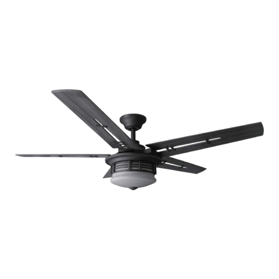
52” Pendleton Thank you for purchasing this Hampton Bay ceiling fan. This product has been manufactured with the highest standards of safety and quality. The finish Ceiling Fan by Hampton Bay of this fan is weather resistant, but over time will naturally weather and fade. -
Page 3: Safety Rules 1
READ AND SAVE THESE INSTRUCTIONS To avoid personal injury or damage to the fan and To reduce the risk of electric shock, insure electricity other items, be cautious when working around or has been turned off at the circuit breaker or fuse box cleaning the fan. -
Page 4: Unpacking Your Fan
Unpack your fan and check the contents. You should have the following items: Blade Hardware 1. Mounting Plate (inside Canopy) 8. Switch Cup (45 Screws) 2. Downrod and Ball Assembly 9. Light Kit Assembly Mounting & Electrical Hardware 3. Canopy 10. -
Page 5: Tools Required
LIGHTING FIXTURES MAY NOT BE ACCEPT- installation hanger bar as shown in Figure 4 ABLE FOR FAN SUPPORT AND MAY NEED TO (available at your Hampton Bay retailer). BE REPLACED. CONSULT A QUALIFIED ELEC- TRICIAN IF IN DOUBT. Installing Your Fan 3. -
Page 6: Hanging The Fan
Hanging the Fan 4. Loosen, but do not remove, the set non-slotted screws and loosen the slotted screws on the collar on the top of the screws. This will enable you to remove the REMEMBER motor housing. turn pow- mounting plate (Figure 6). er. -
Page 7: Making Electrical Connections
Installing Fan to tape. Make sure there are no loose strands or connections (Figure 8). the Outlet Box 1. Connect both green wires from the down- rod and mounting plate to the bare copper 1. Pass the 120-volt supply wires through the (Ground) from the outlet box. - Page 8 Finishing the Fan Installation EACH WIRE NUT (WIRE CONNECTOR) SUP- PLIED WITH THIS FAN IS DESIGNED TO ACCEPT UP TO ONE 12 GAUGE HOUSE WIRE AND TWO WIRES FROM THIS FAN. IF YOU HAVE LARGER STANDARD CEILING MOUNTING THAN 12 GAUGE HOUSE WIRING OR MORE THAN ONE HOUSE WIRE TO CONNECT TO THE FAN WIRING, CONSULT AND ELECTRICIAN FOR WHEN USING THE STANDARD BALL/DOWN-...
- Page 9 Attaching the Fan Blades Screws 1. Attach medallion to blade using two washer head screws supplied (Figure 9). Start a screw into the blade. Repeat for the remain- ing screw. Blade Bracket Blade Figure 11 Figure 10 Blade Balancing TO REDUCE RISK OF PERSONAL INJURY, All blades are grouped by weight.
- Page 10 Installing the Light 7. Re-install the mounting screw that was re- moved in step 4 and tighten firmly. Kit/ Glass Bowl 8. Remove the finial, hex nut and rubber washer from the threaded nipple. CAUTION - To reduce the risk of electrical 9.
-
Page 11: Operating The Fan
Transmitter Operation The fan shipped from the factory with the re- versing switch positioned to circulate air down- Remote Control - Your fan is equipped with a ward. If airflow is desired in the opposite direc- remote control to operate the speed and light for tion, turn your fan off and wait for the blades your new ceiling fan. -
Page 12: Care Of Your Fan
Care of Your Fan Problem Solution Fan will not start Check main and branch circuit fuses or breakers Here are some suggestions to help you maintain your fan. Check line wire connections to the fan and switch wire connections in the switch housing. -
Page 13: Specifications 11
GROSS CUBE FAN SIZE SPEED VOLTS AMPS WATTS WEIGHT WEIGHT FEET 0.29 1980 22.5 25.8 52” 0.44 3672 High 0.55 5573 These are approximate measures. They do not include Amps and Wattage used by the light kit. Distributed by Your Other Warehouse LLC 12100 Little Cayman Dr. -
Page 14: Warranty Information
You must present a copy of the original Hampton Bay also warrants that all other fan parts, excluding any glass or acrylic blades, to be free purchase receipt to obtain warranty service. - Page 15 Pendleton de 52” Gracias por comprar este ventilador de techo de Hampton Bay. Este producto se ha fabricado con las normas de seguridad y calidad más altas. El acabado Ventilador de techo de Hampton Bay de este ventilador es resistente a la intemperie, pero con el tiempo, exhibirá...
-
Page 16: Normas De Seguridad
LEE LAS INSTRUCCIONES Y GUÁRDALAS Para evitar lesiones, o daños al ventilador y otros objetos; ten Para disminuir el riesgo de descarga eléctrica, asegúrate de que cuidado al trabajar cerca del ventilador o al limpiarlo. la electricidad ha sido apagada en el cortacircuitos o la caja de fusibles antes de comenzar la instalación. -
Page 17: Cómo Desempacar El Ventilador 2
Desempaca tu ventilador y revisa el contenido. Deberá tener las siguientes piezas: Herrajes de las aspas (45 tornillos) 1. Placa de montaje (dentro de la cubierta) 8. Caja del interruptor Herrajes de montaje y electricidad 2. Ensamblado de tubo bajante y bola 9. -
Page 18: Cómo Instalar El Ventilador
TAL VEZ DEBAN REEMPLAZARSE. EN CASO como se muestra en la Figura 4 (disponible en DE DUDA, CONSULTA A UN ELECTRICISTA la tienda minorista local de Hampton Bay). CALIFICADO. 3. Cómo instalar el ventilador... - Page 19 Cómo colgar el 4. Afloja, sin quitarlos, los tornillos en el 3. Inserta los cables que salen por la parte collarín ubicado en la parte superior de la superior del motor del ventilador, primero, a ventilador carcasa de motor. través de la cubierta decorativa del collarín 5.
- Page 20 Cómo instalar el ventilador aislante. Asegúrate de que no haya cables o Tornillos de conexiones sueltas (Figura 8). Caja eléctrica en la caja eléctrica montaje aprobada (incluidos con 1. Une los cables verdes del tubo bajante y la por UL la caja eléctrica) 1.
- Page 21 Finalizar la instalación CIRCUITO DE SUMINISTRO del ventilador CADA TUERCA DE CABLE (CONECTOR DE CABLE) PROVISTA CON ESTE VENTILADOR ESTÁ DISEÑADA PARA ACEPTAR CABLES MONTAJE DE TECHO ESTÁNDAR DOMÉSTICOS DE MÁXIMO UN CALIBRE 12 Y DOS CABLES DEL VENTILADOR. SI TIENES UN CABLEADO DOMÉSTICO DE CALIBRE SUPERIOR A 12 O MÁS DE UN CABLE RECEPTOR...
- Page 22 Cómo montar las aspas Punto en del ventilador el techo Tornillos 1. Fija el medallón al aspa con los dos tornillos de cabeza de arandela provistos (Figura 9). Inserta el tornillo en el aspa. Repite el paso con el otro tornillo. Soporte Aspa de aspa...
- Page 23 Cómo instalar el kit el ensamblado del kit de luces sobre los dos tornillos, gíralo de izquierda a derecha hasta de luces/tazón de vidrio trabarlo y después aprieta los dos tornillos. 7. Reinstala el tornillo de montaje que retiraste PRECAUCIÓN – Para disminuir el riesgo de en el paso 4 y apriétalo firmemente.
-
Page 24: Cómo Operar El Ventilador
Funcionamiento del Tecla Off - Apagado transmisor Tecla Light - Encender/Apagar la luz Control remoto - Tu ventilador está equipado Las configuraciones de velocidad para clima con un control remoto que controla la velocidad cálido o frío dependen de factores como tamaño y la luz de tu ventilador de techo. -
Page 25: Cuidado Del Ventilador
Cuidado del ventilador Problema Solución El ventilador no Verifica fusibles o disyuntores principales y secundarios. Aquí tienes algunas sugerencias para el enciende mantenimiento de tu ventilador. Verifica conexiones de cables en línea al ventilador y conexiones de cables del interruptor en la caja de interruptores. PRECAUCIÓN: 1. -
Page 26: Especificaciones
PIES CÚB. PESO PESO PIES TAMAÑO VELOCIDAD VOLTIOS AMPERIOS VATIOS X MIN. NETO BRUTO CÚB. Baja 0.29 1980 22.5 25.8 52” Media 0.44 3672 Alta 0.55 5573 Estas medidas son aproximadas. No incluyen ni el amperaje ni el vataje consumido por el kit de luces. Distribuido por Your Other Warehouse LLC 12100 Little Cayman Dr. -
Page 27: Información De La Garantía 12
Hampton Bay garantiza de por vida, a partir de la fecha de compra por el comprador original, que el motor del ventilador no presenta defectos de fabricación ni de material desde la fecha de salida de Usted debe presentar una copia del la fábrica.
Need help?
Do you have a question about the PENDLETON and is the answer not in the manual?
Questions and answers
What is the remote number. Mine doesn't work